BlueOptics X2 to SFP+ Converter 10Gigabit
•
0 likes•65 views

BlueOptics X2 to SFP+ Converter 10Gigabit

Recommended
Recommended
More Related Content
What's hot
What's hot (20)
Viewers also liked
Viewers also liked (13)
Similar to BlueOptics X2 to SFP+ Converter 10Gigabit
Similar to BlueOptics X2 to SFP+ Converter 10Gigabit (11)
More from CBO GmbH
More from CBO GmbH (20)
Recently uploaded
Recently uploaded (20)
BlueOptics X2 to SFP+ Converter 10Gigabit
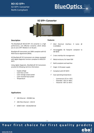
- 1. BO-X2-SFP+ X2 SFP+ Converter RoHS Compliant - 1 - X2 SFP+ Converter Description The BlueOptics© BO-X2-SFP+ X2 converter is a high performance, cost effective converter, which allows you to use a SFP+ Module in an X2 port. BlueOptics© transceivers are 100% compliant with X2 Multi-Source Agreement (MSA). All BlueOptics© X2 transceivers are always equipped with digital diagnostic function compliant to MSA SFF- 8472. Using digital diagnostic, BlueOptics© X2 transceivers provide the following real time information: - Supply voltage - Laser bias current - Laser average output power - Laser received input power - Temperature Applications 10G Ethernet – IEEE802.3ae 10G Fibre Channel – 1413-D SONET/ SDH – OC192/SDH-64 Features XAUI Electrical Interface: 4 Lanes @ 3.125GBit/s Hot-pluggable X2 footprint compliant to INF-8476 2-wire interface for management Metal enclosure, for lower EMI RoHS compliant and lead-free Single +3.3V power supply Compliant with SFF-8472 Case operating temperature - Commercial: 0°C to +70°C - Extended: -10°C to +80°C - Industrial: -40°C to +85°C
- 2. BO-X2-SFP+ X2 SFP+ Converter RoHS Compliant - 2 - Warnings Handling Precautions: This device is susceptible to damage as a result of electrostatic discharge (ESD). A static free environment is highly recommended. Laser Safety: Even small radiation emitted by laser devices can be dangerous to human eyes and lead to permanent eye injuries. Be sure to avoid eye contact with direct or indirect radiation. Warranty Every BlueOptics© transceiver comes with a 5 year replacement warranty and lifetime support. For a warranty inquiry, please contact your CBO sales representative. This warranty only covers the first user of the equipment. Important Notice Performance figures, data and any illustrative material provided in this data sheet are typical and must be specifically confirmed in writing by CBO before they become applicable to any particular order or contract. In accordance with the CBO policy of continuous improvement specifications may change without notice. The publication of information in this data sheet does not imply freedom from patent or other protective rights of CBO or others. Further details are available from any CBO sales representative. Installation Before installation attach an ESD-preventive wrist to ensure not to damage the transceiver or hardware. BlueOptics© BO-X2-SFP+ can be installed in any Small Form Factor Pluggable X2 port. You can install the BO-X2-SFP+ regardless if the system is powered on or off, because it is hot-swappable. Insert the transceiver into the X2 port and remove the dust cap. You can now insert the SFP+ Module and connect the patch cord. Order Information Part No. Temp. DDM BO-X2-SFP+ 0°C to +70°C BO-X2-SFP+EX -10°C to +80°C BO-X2-SFP+IN -40°C to +80°C Regulatory Compliance Feature Standard Co. Electrostatic Discharge (ESD) - IEC/EN 61000-4- 2 Electromagnetic Interference (EMI) - FCC Part 15 Class B EN 55022 - Class B (CISPR 22A) Laser Eye Safety - FDA 21CFR 1040.10, 1040.11 - IEC/EN 60825-1, 2 Class 1 Component Recognition - IEC/EN 60950, UL RoHS - 2002/95/EC EMC - EN61000-3
- 3. BO-X2-SFP+ X2 SFP+ Converter RoHS Compliant - 3 - 1. Absolute Maximum Ratings Parameter Symbol Min. Typ. Max. Unit Storage Temperature Ts -40 85 ºC Storage Ambient Humidity HA 5 95 % 2. Recommended Operating Conditions Parameter Symbol Min. Typ. Max. Unit Note Case Operating Temperature Tcase 0 70 BO-X2-SFP+ -10 80 ºC BO-X2-SFP+EX -40 85 BO-X2-SFP+IN Ambient Humidity HA 5 70 % 3. Electrical Interface Characteristics Parameter Symbol Min. Typ. Max. Unit Note Power Supply Voltage Vcc 3.13 3.3 3.45 V Power Supply Current Icc1 1.0 A Power Supply Current Icc2 1.7 A Power Consumption PDS 4.0 W Power supply stabilization time TDF 500 ms Initialization Time TINIT 5 S RESET Assert Time TRESET 1 Ms Hold Time after rising edge of RESET THOLD 500 ms 4. XAUI Driver Characteristics Parameter Symbol Min. Typ. Max. Unit Note Baud Rate 3.125 Gbit/s Baud Rate Tolerance -100 +100 ppm Differential Amplitude 800 1600 mVPP 5. X2 to Host Connector Pin Out Pin Symbol I/O Logic Description 1 GND I Supply Electrical ground 2 GND I Supply Electrical ground 3 GND I Supply Electrical ground 4 Reserved - - Reserved 5 3.3 V I Supply Power 6 3.3 V I Supply Power 7 APS I Supply Adaptive Power Supply 8 APS I Supply Adaptive Power Supply 9 LASI O Open Drain Link Alarm Status Interrupt. 10-22k ohm pull up on host. 10 RESET I 1.2V CMOS TX OFF when MDIO RESET 11 VEND SPECIFIC - - Vendor Specific Pin. Leave unconnected.
- 4. BO-X2-SFP+ X2 SFP+ Converter RoHS Compliant - 4 - 12 TX ON/OFF I 1.2V CMOS Transmitter ON/OFF 13 Reserved - - Reserved 14 MOD DETECT O - Pulled low inside module through 1k ohm. 15 VEND SPECIFIC - - Vendor Specific Pin. Leave unconnected. 16 VEND SPECIFIC - - Vendor Specific Pin. Leave unconnected. 17 MDIO I/O Open Drain Management Data IO 18 MDC I 1.2V CMOS Management Data Clock 19 PRTAD4 I 1.2V CMOS Port Address bit 4 (Low=0) 20 PRTAD3 I 1.2V CMOS Port Address bit 3 (Low=0) 21 PRTAD2 I 1.2V CMOS Port Address bit 2 (Low=0) 22 PRTAD1 I 1.2V CMOS Port Address bit 1 (Low=0) 23 PRTAD0 I 1.2V CMOS Port Address bit 0 (Low=0) 24 VEND SPECIFIC - - Vendor Specific Pin. Leave unconnected. 25 APS SET O - Feedback output for APS 26 RESERVED - - Reserved for Avalanche Photodiode use 27 APS SENSE O Analog APS Sense Connection 28 APS I Supply Adaptive Power Supply 29 APS I Supply Adaptive Power Supply 30 3.3 V I Supply Power 31 3.3 V I Supply Power 32 Reserved - - Reserved 33 GND I Supply Electrical Ground 34 GND I Supply Electrical Ground 35 GND I Supply Electrical Ground 36 GND I Supply Electrical Ground 37 GND I Supply Electrical Ground 38 Reserved - - Reserved 39 Reserved - - Reserved 40 GND I Supply Electrical Ground 41 RX LANE 0+ O AC Module XAUI Output Lane 0+ 42 RX LANE 0- O AC Module XAUI Output Lane 0- 43 GND I Supply Electrical Ground 44 RX LANE 1+ O AC Module XAUI Output Lane 1+ 45 RX LANE 1- O AC Module XAUI Output Lane 1- 46 GND I Supply Electrical Ground 47 RX LANE 2+ O AC Module XAUI Output Lane 2+ 48 RX LANE 2- O AC Module XAUI Output Lane 2- 49 GND I Supply Electrical Ground 50 RX LANE 3+ O AC Module XAUI Output Lane 3+ 51 RX LANE 3- O AC Module XAUI Output Lane 3- 52 GND I Supply Electrical Ground 53 GND I Supply Electrical Ground 54 GND I Supply Electrical Ground 55 TX LANE 0+ I AC Module XAUI Input Lane 0+ 56 TX LANE 0- I AC Module XAUI Input Lane 0-
- 5. BO-X2-SFP+ X2 SFP+ Converter RoHS Compliant - 5 - 57 GND I Supply Electrical Ground 58 TX LANE 1+ I AC Module XAUI Input Lane 1+ 59 TX LANE 1- I AC Module XAUI Input Lane 1- 60 GND I Supply Electrical Ground 61 TX LANE 2+ I AC Module XAUI Input Lane 2+ 62 TX LANE 2- I AC Module XAUI Input Lane 2- 63 GND I Supply Electrical Ground 64 TX LANE 3+ I AC Module XAUI Input Lane 3+ 65 TX LANE 3- I AC Module XAUI Input Lane 3- 66 GND I Supply Electrical Ground 67 Reserved - AC Reserved 68 Reserved - AC Reserved 69 GND I Supply Electrical Ground 70 GND I Supply Electrical Ground
- 6. BO-X2-SFP+ X2 SFP+ Converter RoHS Compliant - 6 - 6. EEPROM Information Device Address (Dec) Register Address (Hex) PMA/PMD 1 PCS 3 PHY XS 4 0x0000 PMA/PMD Control1 PCS Control1 PHY XS Control1 0x0001 PMA/PMD Status1 PCS Status1 PHY XS Status1 0x0002 PMA/PMD Device Identifier0 PCS Device Identifier0 PHY XS Device Identifier0 0x0003 PMA/PMD Device Identifier1 PCS Device Identifier1 PHY XS Device Identifier1 0x0004 PMA/PMD Speed Ability PCS Speed Ability PHY XS Speed Ability 0x0005 PMA/PMD Device in Package1 PCS Device in Package1 PHY XS Device in Package1 0x0006 PMA/PMD Device in Package2 PCS Device in Package2 PHY XS Device in Package2 0x0007 10G PMA/PMD Control2 PCS Control2 Reserved 0x0008 10G PMA/PMD Status2 PCS Status2 PHY XS Status2 0x0009 Reserved Reserved Reserved 0x000A Reserved Reserved Reserved 0x000E Reserved Reserved Reserved 0x000F Reserved Reserved Reserved 0x0018 Reserved Reserved 10G PHY XGXS Lane Status 0x0019 Reserved Reserved 10G PHY XGXS Test Control 0x0020 Reserved 10GBASE-R PCS Status1 Reserved 0x0021 Reserved 10GBASE-R PCS Status2 Reserved 0x0022 Reserved 10GBASE-R PCS Test pattern Seed A0 Reserved 0x0023 Reserved 10GBASE-R PCS Test pattern Seed A1 Reserved 0x0024 Reserved 10GBASE-R PCS Test pattern Seed A2 Reserved 0x0025 Reserved 10GBASE-R PCS Test pattern Seed A3 Reserved 0x0026 Reserved 10GBASE-R PCS Test pattern Seed B0 Reserved 0x0027 Reserved 10GBASE-R PCS Test pattern Seed B1 Reserved 0x0028 Reserved 10GBASE-R PCS Test pattern Seed B2 Reserved
- 7. BO-X2-SFP+ X2 SFP+ Converter RoHS Compliant - 7 - 0x0029 Reserved 10GBASE-R PCS Test pattern Seed B3 Reserved 0x002A Reserved 10GBASE-R PCS Test pattern Control Reserved 0x002B Reserved 10GBASE-R PCS Test pattern Error counter Reserved 0x8000 NVR Control/Status (X2 Register) Reserved 0x8007 - 0x807D NVR (X2 Register) Reserved 0x807E- 0x80AD Customer AREA Reserved 0x80AE - 0x8106 Vendor Specific Reserved 0x9000 RX_ALARM Control (X2 Register) Reserved 0x9001 TX_ALARM Control (X2 Register) Reserved 0x9002 LASI Control (X2 Register) Reserved 0x9003 RX_ALARM Status (X2 Register) Reserved 0x9004 TX_ALARM Status (X2 Register) Reserved 0x9005 LASI Status (X2 Register) Reserved 0x9006 TX_FLAG Control Bits Reserved 0x9007 RX_FLAG Control Bits Reserved 0xA000 - 0xA027 Alarm and Warning Thresholds Reserved 0xA060 - 0xA069 Digital Optical Monitoring Interface Reserved 0xA06F DOM Capability - Extended Reserved 0xA070 TX_ALARM_FLAG Bits Reserved 0xA071 RX_ALARM_FLAG Bits Reserved 0xA074 TX_WARNING_FLAG Bits Reserved 0xA075 RX_WARNING_FLAG Bits Reserved 0xA100 Optional Digital Optical Monitoring (DOM) Control/Status Reserved 7. Digital Diagnostics / Digital Optical Monitoring The transceiver provides serial ID memory contents and diagnostic information about the present operating conditions by the 2-wire serial interface (SCL, SDA). The diagnostic information with internal calibration or external calibration are all implemented, including received power monitoring, transmitted power monitoring, bias current monitoring, supply voltage monitoring and temperature monitoring.
- 8. BO-X2-SFP+ X2 SFP+ Converter RoHS Compliant - 8 - 8. Mechanical Specifications (Unit: mm) Contact Information CBO GmbH Friedhofstraße 25 45478 Mülheim an der Ruhr Germany Tel.: 0049 – 208 – 777 247 - 0 Fax.: 0049 – 208 – 777 247 - 99 eMail: info@cbo-it.de web: www.cbo-it.de