SlideShare a Scribd company logo
1 of 86
Download to read offline
EA001J
(Supersedes EA001H)
Aeroquip
Reusable Hose and
Reusable
Fittings
Schläuche und
Wiederverwendbare
Armaturen
Tuyaux et embouts
réutilisables
Tubi flessibili e raccordi
riutilizzabili
Mangueras y racores
reutilizables
Index
Inhaltsverzeichnis
Table des matières
Indice
Part Number Index
Teilnummernverzeichnis
Index alphanumérique des références
Indice dei riferimenti
Indice de las referencias
4 How to use this catalogue
6 Order Information
9–25 Hose
28–33 Fittings Low Pressure
35 Fittings Low Pressure and Vacuum
38–46 Fittings Medium Pressure
50–56 Fittings High Pressure
60–64 Fittings Super High Pressure
66–75 Accessories
76–84 Technical Information
4 Wie wird mit diesem Katalog gearbeitet?
6 Bestellinformationen
9–25 Schläuche
28–33 Armaturen für Niederdruck
35 Armaturen für Niederdruck und Vakuum
38–46 Armaturen für Mitteldruck
50–56 Armaturen für Hochdruck
60–64 Armaturen für Super-Hochdruck
66–75 Zubehör
76–84 Technische Hinweise
5 Comment utiliser ce catalogue
7 Instructions de commande
9–25 Tuyaux
28–33 Embout basse pression
35 Embout basse pression et tenue au vide
38–46 Embout moyenne pression
50–56 Embout haute pression
60–64 Embout très haute pression
66–75 Accessoires
76–84 Informations techniques
5 Come usare questo catalogo
7 Indicazioni per gli ordini
9–25 Tubi flessibili
28–33 Raccorderia per bassa pressione
35 Raccorderia per bassa pressione e vuoto
38–46 Raccorderia per media pressione
50–56 Raccorderia per alta pressione
60–64 Raccorderia per altissima pressione
66–75 Accessori
76–84 Informazioni techniche
5 Como ha de usarse este catalogo
7 Como efectuar los pedidos
9–25 Mangueras
28–33 Racores para bajas presiones
35 Racores para bajas presiones y vacío
38–46 Racores para medias presiones
50–56 Racores para altas presiones
60–64 Racores para presiones muy elevadas
66–75 Accesorios
76–84 Indicaciones téchnicas
Part-No. Page Part-No. Page Part-No. Page
Seite Seite Seite
Pagina Pagina Pagina
FC234 16
FC300 13
FC310 21
FC318 12
FC332 9
FC350 14
FC355 15
G1210 13–19
G1212 13–19
G185261 43
G185264 53
G185265 43
G185287 53
G185296 43
G185297 43
G185299 43
G185302 43
G2401 42
G2411 42
G4007 25
G4010 22, 23
G4013 24, 25
G4103 52, 61
G4202 54
G4614 54, 61
G4645 54
G4675 38
G4677 38
G4679 38
G4690 55, 62
G74446 66
G74453 67
GA10736 46
GA10933 50
GA15063 50
GA15065 39
GA15067 39
GA15069 28
GA15705 28
GA15711 28
GA15772 39
GA17089 20, 21
GA17537 50
GA17544 50
GA17586 50
GC2453 68
GC2542 20, 21
GC3425 67
GC6370 62
GC6374 62
GF9311 11, 12
GH195 22
GH663 20
SH222 24
05.010 9, 10
05.018 66–68
11.002 40
11.003 41
11.005 52, 61
11.006 29
11.011 45
11.013 52
11.020 63
11.021 30
11.027 41
11.030 40
11.031 41
11.045 44
11.057 31
11.072 29
11.074 29
11.122 32
11.139 56, 63
11.140 32
11.143 55
11.144 32
11.187 45
11.327 56
11.340 45
11.390 31
11.391 33
11.420 55, 63
11.421 44
11.721 51, 60
11.839 51, 60
11.840 51, 60
11.841 60
1S-FJ- 35
1S-FL 35
1S-MP- 35
1251 42
1252 44
1503 17
185287 53
23055 69, 70
2412 44
2556 10
26U51B 18
2651 19
2652 19
2661 11
2755 25
2781 23
4202 54
4203 53, 64
4738 30
4797 30, 31
624 72
900564 73
900705 74
900729 71
900952 75
Page
Seite
Pagina
Aeroquip
2
Benefits of Eaton’s Aeroquip Bulk Hose and
Reusable Fittings
1. Reduce downtime on equipment when
replacement of hose line is required by
reusing the fittings with bulk hose.
2. When fitting replacement is necessary, a few
fittings with bulk hose provide the ability to
assemble any required hose line.
3. All types of equipment can be serviced with
the same hose and fitting inventory.
4. Hose assemblies can be made on the job
using hand tools.
5. Equipment plumbed with reusable fitting
hose assemblies carries a built-in fitting
inventory when hose must be replaced.
Aeroquip Corporation was founded in 1940 to
manufacture and sell a new type of reusable
fitting for high pressure hose lines. The idea
then, and now, was that a reusable fitting would
reduce the cost of replacing hose lines and
through its field assembly capability, reduce
equipment downtime when a hydraulic hose
line needed replacing.
It is equally unthinkable to stop a production
line or deadline for an expensive piece of con-
struction equipment while a hose line is shipped
from the factory.
Eaton’s Aeroquip also offers a comprehensive
range of crimped end fittings to suit a wide
selection of Aeroquip hose styles, many of which
are detailed in Aeroquip Catalogues EA 005 and
EA 011.
Furthermore, while sophisticated equipment
is available for high volume hose and fitting
assembly operations, you can still put Aeroquip
fittings and hose together with a few simple
hand tools.
Eaton’s Aeroquip Schlauch-Meterware und wieder-
verwendbare Armaturen bringen Gewinn
1. weil die Stillstandzeiten von Maschinen und
Anlagen verkürzt werden, wenn eine defekte
Schlauchleitung schnell durch ein Stück neuen
Schlauch mit den vorhandenen Armaturen
ersetzt wird;
2. weil einige wenige Armaturen und ein paar
Meter Schlauch genügen, um jede benötigte
Schlauchleitung auch mit neuen Armaturen
anzufertigen;
3. weil fast jede Art von hydraulischem Gerät aus
dem gleichen kleinen Vorrat von Schlauch-
Meterware und Armaturen versorgt werden
kann;
4. weil Schlauchleitungen mit einfachem Hand-
werkzeug an Ort und Stelle einzubauen sind;
5. weil von Haus aus mit wiederverwendbaren
Schlaucharmaturen ausgerüstete Maschinen die
für eine etwa zu ersetzende Schlauchleitung
benötigten Armaturen gleich mitbringen.
Aeroquip Corporation wurde 1940 für die
Produktion und den Vertrieb eines neuartigen Typs
von wiederverwendbaren Armaturen für Hoch-
druckschläuche gegründet. Damals wie heute stand
dahinter die Idee, daß eine wiederverwendbare
Armatur die Kosten für Schlauchleitungs-Ersatz
reduzieren und durch die mögliche Feldmontage
überdies die Stillstandzeit von Maschinen verkür-
zen muß, wenn eine Leitung auszuwechseln ist.
Undenkbar ist es heute, eine Walzstraße
anzuhalten oder eine kostspielige Baumaschine
stillzulegen, während eine Schlauchleitung vom
Herstellerwerk zum Einsatzort – womöglich weit
entfernt im Ausland – unterwegs ist.
Eaton’s Aeroquip bietet auch eine breite Palette
verschiedener Preßarmaturen für eine große An-
zahl von Aeroquip Schläuchen an. Viele davon sind
in den Katalogen EA 005 und EA 011 mit ihren
technischen Daten angeführt.
Dennoch weist die wiederverwendbare Eaton’s
Aeroquip Schlaucharmatur nach wie vor den wirt-
schaftlichsten Weg, Verluste durch den Stillstand
teurer Maschinen wegen einer ausgefallenen Lei-
tung zu vermeiden. Die Montageeinrichtungen zur
Massenproduktion von industriell gefertigten
Schlauchleitungen sind im Laufe der Jahre immer
vollkommener geworden – Eaton’s Aeroquip
Schlauch und wiederverwendbare Armaturen aber
können wie eh und je von Hand mit einfachem
Werkzeug zu einer zuverlässigen Schlauchleitung
zusammengefügt werden.
Eaton’s Aeroquip =
the Reusable Fitting
Concept
Eaton’s Aeroquip =
Philosophie der wiederver-
wendbaren Schlaucharmatur
3
Avantages et bénéfices des embouts réutilisables
et tuyaux stockés séparément:
1. Réduction du temps d’immobilisation de
l’équipement sur lequel une tuyauterie doit
être remplacée.
2. La nouvelle tuyauterie peut être fabriquée
sur place avec les anciens embouts et un
nouveau morceau de tuyau.
3. Quand les embouts doivent être remplacés,
quelques embouts, un peu de tuyau en stock
permettent de fabriquer une autre tuyau-
terie.
4. Par une standardisation judicieuse sur les
équipements ou engins d’un parc donné, un
stock réduit de tuyaux et d’embouts consti-
tuera la rechange suffisante.
5. Les tuyauteries de remplacement peuvent
être faites in situ, sur chantier, dans les
ateliers de production.
Les machines, les engins équipés de tuyauteries
à embouts réutilisable sont partie intégrale du
stock d’embouts nécessaire à la rechange ...
puis-que les embouts peuvent être réutilisés.
La société Aeroquip Corporation fut fondée en
1940 pour la fabrication et la diffusion d’un type
entièrement nouveau d’embouts réutilisables.
L’idée à l’époque, toujours aussi valable aujour-
d’hui d’ailleurs était que l’utilisation d’embouts
réutilisables réduirait le coût de la rechange, et,
par sa possibilité de montage in situ, réduirait
aussi le temps d’immobilisation de l’équipement
arrêté par une tuyauterie défaillante.
Donc, double économie.
Aeroquip propose également une gamme com-
plete d’embouts sertis qui se montent avec de
nombreux tuyaux dont la plupart sont descrits
dans les catalogues EA 005 et EA 011.
Et, bien que des équipements très sophistiqués
soient disponibles pour le montage en grande
série des tuyauteries vous pourrez toujours
assembler le tuyau et les embouts réutilisables
Aeroquip avec un outillage réduit à deux clés.
Benefici e vantaggi dei tubi Eaton’s Aeroquip
con raccordi riutilizzabili
1. Riducono il tempo di immobilizzo delle
macchine sulle quali si rende necessaria la
sostituzione di tubi, permettendo di riutiliz-
zare il raccordo su un nuovo tubo flessibile.
2. Una scorta di pochi raccordi e un rotolo di
tubo flessibile consentono di realizzare in
pochi minuti qualsiasi collegamento caso di
necessario ricambio.
3. Ogni tipo di macchina, anche con molti tubi,
può avvalersi di una piccola scorta di un solo
tipo di tubo e raccordi per ogni urgente eve-
nienza.
4. I tubi possono essere assemblati sul posto
manualmente, per mezzo di semplici utensili.
5. Le macchine e gli impianti equipaggiati con
tubi e raccordi riutilizzabili Aeroquip non
hanno necessità di una scorta di raccordi in
quanto quelli già montati sulla macchina o
sull’impianto possono sempre essere riutiliz-
zati.
La Aeroquip Corporation fu fondata nel 1940 per
la costruzione e la diffusione di un nuovo tipo di
raccordo riutilizzabile per tubi flessibili adatti ad
alte pressioni. L’idea, valida allora come oggi,
era quella che attraverso la riutilizzazione degli
stessi raccordi si poteva ridurre il costo dei
ricambi dei tubi flessibili ed il tempo di immo-
bilizzo di macchine, ferme a causa di tubi difet-
tosi, mediante l’assemblaggio del tubo sul posto.
Oggi è impensabile da tenere ferma una produ-
zione, un impianto o un macchinario, solo per-
chè si deve attendere dallo stabilimento di pro-
duzione il ricambio di un tubo rotto.
Anche se nel corso degli anni la produzione
Aeroquip si è estesa ed ha incluso la fabbricazio-
ne di tubi con raccordi graffati, che si possono
assemblare sul posto, il concetto dei tubi con
raccordi riutilizzabili rimane la migliore assicu-
razione contro inutili perdite di tempo, causate
dalla rottura di tubi per condotta di fluidi.
L’Aeroquip dispone anche di una vasta gamma
di raccordi di tipo graffato, che possono esere
assemblati su molti tubi, descritti in questo
catalogo, e su altri, riportati in modo dettagliato
nei cataloghi EA 005 ed EA 011.
Ventajas del Uso de la Manguera Eaton’s Aero-
quip en Rollos y las Conexions Reutilizables
1. Se reduce al mínimo el tiempo que no está
trabajando una máquina o un equipo a causa
de una manguera dañada. Se repone única-
mente el tramo de la manguera, utilizando
las mismas conexiones desmontables.
2. Unas cuantas conexiones y unos rollos de
manguera proporcionan lo necesario para
hacer cualquier línea cuando se necesiten
ensambles de repuesto en una emergencia.
3. Se puede dar servicio a todos los tipos de
equipo y maquinaria con una mínima
existencia de mangueras y conexiones.
4. Se pueden hacer ensambles de mangueras en
el taller, en la planta, en el campo o en el
sitio que sea, usando solmente herramienta
de mano.
5. La maquinaria equipada con ensambles de
manguera con las conexiones reutilizables
ya lleva las conexiones necesarias y listas
para usarse cuando haya que reponer una
manguera.
Aeroquip Corporation fue fundada en 1940 para
fabricar y vender un nuevo tipo de conexiones
reutilizables para hacer ensambles de mangue-
ras para trabajar a alta presión. La idea en aquel
tiempo tanto como hoy en día fue que una cone-
xión desarmable y reutilizable reduciría el costo
de reposición. Además incorporó la facilidad de
poder hacer el ensamble de repuesto en cual-
quier sitio, reduciendo así el tiempo que no
estaba trabajando un equipo o una máquina
por falta de una línea hidráulica.
Hoy es igualmente importante evitar paros en
una línea de producción industrial o en el uso
de equipo para construcción y no tener que es-
perar a que llegue del fabricante original una
nueva manguera de reposicion.
Aeroquip también ofrece una gama completa
de racores prensados que se ajustan a la amplis
selección de estilos de tuberias Aeroquip,
muchos de los cuales están detallados en los
catálogos de Aeroquip EA 005 y EA 011.
La conexión Aeroquip - desarmable y reutiliza-
ble - sigue siendo la mejor forma de evitar que
un costoso equipo se quede sin trabajar debido a
fallas de mangueras conduciendo cualquier sus-
tancia. Aunque hay disponibles máquinas espe-
ciales para armar mangueras y conexiones en
gran volumen éstas siempre pueden ensamblar-
se también en situaciones difíciles utilizando
herramienta sencilla de mano.
Eaton’s Aeroquip =
philosophie de l’embout
réutilisable
Eaton’s Aeroquip =
il Concetto dei Raccordi
Riutilizzabili
Eaton’s Aeroquip = El
Concepto de las Conexiones
Desmontables y Reutilizables
4
˚C
˚C max
Max. Op. ˚C
Air ˚C max
Part No.
Op. Press.
Max. Op. Press.
Min. Burst Press.
Min. Bend Rad.
Hose ID
Hose OD
This brochure has been designed to incorporate
five languages, English, German, French, Italian
and Spanish. For Technical Data, abbreviations,
symbols and translations have been used, see de-
tailed explanation below.
Symbols and Abbreviations
Temperature range in degrees celsius
Maximum temperature in degrees celsius
Maximum operating temperature in degrees
celsius
Air maximum temperature in degrees celsius
Diameter in mm
Hexagon size across flats in mm
Part Number
Operating Pressure in bar
Maximum operating pressure in bar
Minimum burst pressure in bar
Minimum bend radius in mm
Hose inside diameter in mm
Hose outside diameter in mm
Accessories
Angle in Degrees
Diameter (DN)
Dimension
Front view
Flange
For nipples see pages
Hose
Hose caps must be odered
separately
Hose cap
Hose clamp
Letter key a
Measure Angle Counter Clockwise
Measurement ecc.
Metric thread
Nipple for hose
Page
Part number complete with cap
Position angle K
Socket
Standpipe Ø
Thread
Weight
Vacuum in bar
Bolt
Dieser Katalog enthält fünf Sprachen:
Englisch, Deutsch, Französisch, Italienisch und
Spanisch. Für die technischen Daten wurden
Abkürzungen, Symbole und Übersetzungen ver-
wendet. Siehe genaue Erklärungen unten.
Symbole und Abkürzungen
Temperatur in Grad Celsius
Höchsttemperatur in Grad Celsius
Maximale Betriebstemperatur in Grad
Celsius
Maximale Lufttemperatur in Grad Celsius
Durchmesser in mm
Sechskantgröße in mm (Schlüsselweite)
Teilnummer
Betriebsdruck in bar
Maximaler Betriebsdruck in bar
Mindestberstdruck in bar
Mindestbiegeradius in mm
Schlauch-Innendurchmesser in mm
Schlauch-Außendurchmesser in mm
Leitungszubehör
Verdrehwinkel
Nennweite (DN)
Maß
Vorderansicht
Flansch
Nippel siehe Seiten
Schlauch
Schlauchkappen sind getrennt zu
bestellen
Schlauchkappen
Schlauchschellen
Buchstaben-Schlüssel a
Gegen den Uhrzeigersinn gemessen
Vermaßung nach
Metrisches Gewinde
Nippel für Schlauch
Seite
Komplette Teilenummer mit Schlauchkappen
Verdrehwinkel K
Fassung
Rohraußendurchmesser Ø
Gewinde
Gewicht
Vakuum in bar
Schraube
How to use
this catalogue?
Wie wird mit diesem
Katalog gearbeitet?
5
Ce catalogue est rédigé en cinq langues:
Anglais, Allemand, Francais, Italien, Espagnol.
Des abréviations, symboles et traduction sont
utilisés pour les caractéristiques techniques.
Voir explication précise ci-après.
Symboles et abréviations
Température en degrés Celsius
Température maximum en degrés Celsius
Température maximum de service en degrés
Celsius
Température maximum d’air en degrés Celsius
Diamètre en mm
Dimension du six pans sur plats en mm
Référence
Pression de service en bar
Pression maximum de service en bar
Pression d’eclatement minimum en bar
Rayon de courbure minimum en mm
Diamètre intérieur de tuyau en mm
Diamètre extérieur de tuyau en mm
Accessoires
Angle de rotation
Diamètre (DN)
Dimension
Vue de face
Bride
Pour les nipples voir page
Tuyau
Les bagues de tuyau doivent être commandées
séparément
Les bagues de tuyau
Collier
Code alphabétique a
Sens inverse des aiguilles d’une montre
Mesure selon la norme
Filetage Métrique
Nipples pour tuyaux
Page
Référence complète avec bagues de tuyau integrée
Position de l’embout K
Jupe
Embout lisse Ø
Filetage
Poids
Vide en bar
Boulon
Questo opuscolo é redatto cinque lingue: ingle-
ses, tedesco, francese, italano e spagnolo. Per
quanto riguarda i dati tecnici sono stati adottati
abbreviazioni, simboli e traduzioni. Al riguardo,
si vedano le spiegazioni dettagliate riportate qui
di seguito.
Simboli et abbreviazioni
Temperatura in gradi Celsius
Temperatura massima in gradi Celsius
Temperatura massima de’esercizio in gradi
Celsius
Temperatura massima dell’aria in gradi Celsius
Diametro in mm
Chiave dell’esagono in mm
Riferimento
Pressione d’esercizio in bar
Pressione massima d’esercizio in bar
Pressione minimal di scoppio in bar
Raggio minimo di curvatura in mm
Diametro interno del tubo flessibile in mm
Diametro esterno del tubo flessibile in mm
Accessori
Angolo in gradi
Diametro nominale (DN)
Dimensioni
Vista frontale
Flangia
Per i raccordi vedere alle pagine
Tubo flessibile
I tappi di protezione dei tubi devone essere
ordinati separatamente
I tappi di protezione dei tubi
Fascetta
Chiave lettera a
Misurato antiorario in senso
Dimensione normative
Filettatura metrica
Raccordi per tubi flessibili
Pagina
Riferimento completo incluso il tappo di protezione
Angolo di orientamento K
Boccola
Tubo Ø
Filettatura
Peso
Vuoto in bar
Vite
Este catalogo incluye textos en cinco idiomas:
inglés, alemán, francés, italiano y español. Para
los datos técnicos se emplean abreviaturas, sím-
bolos y traducciones. Consultar al respecto las
explicaciones dadas a continuación.
Símbolos y abreviaturas
Temperatura en grados centígrados
Temperatura máxima en grados centígrados
Temperatura máxima de servicio en grados
centígrados
Temperatua máxima del aire en grados centígrados
Diámetro en mm
Tamaño del hexágono entre caras en mm
Referencia
Presión de servicio en bares
Presión máxima de servicio en bares
Presión mínima de reventamiento en bares
Radio mínimo de curvatura en mm
Diámetro interior de la manguera en mm
Diámetro exterior de la manguera en mm
Accesorios
Angulo de giro
Diámentro nonimal (DN)
Medida, cota o dimensión
Vista frontal
Brida
Para subconjunto ver paginas
Manguera
Los tapones de tuberia deben pedirse por
separado
Los tapones de tuberia
Abrazaderas
Clave alfabética a
Medido en sentido contrario a las agujas del reloj
Medida según
Rosca métrica
Manguitos para mangueras
Página
Referencia complete con tapones
Angulo de giro K
Casquillo
Tubo exterior Ø
Roscaa
Peso
Vacío en bares
Tornillo
Comment utiliser
ce catalogue?
Come usare
questo catalogo?
Cómo ha de usarse
este catalogo?
6
Voraussetzung für eine einwandfreie Abwicklung und eine
schnelle Lieferung Ihres Auftrages ist die fehlerfreie Iden-
tifikation der Teile in Ihrem Auftrag oder Ihrer Anfrage.
Aeroquip Teile müssen mit der richtigen Teilenummer, wie
sie in diesem Katalog gezeigt wird, bestellt werden.
Teil-Nummern und Größen
Die Teilnummer steht für Form und Anschluß eines
Teiles.Die Größe wird mit einem Bindestrich hinten an-
gehängt und gehört verbindlich zur Teilnummer. Die
Größenangabe erfolgt in 1/16".
Beispiel: 2781-8 = 8/16" = 1
/2" = DN12
Bestellbeispiel: Schlauch-Meterware
Länge in m Teil-Nr.
5 0 0 m 2 7 8 1 – 1 2
Bestellbeispiel: Schlauch, abgelängt
Stück Teil-Nr. Länge in mm (5-stellig)
5 5 x F C 3 5 0 – 6 – 0 2 5 0 0
Bestellbeispiel: Schlauchleitung
Stück Teil-Nr. Länge in mm (5-stellig)
2 5 x 2 7 8 1 – 1 0 – 0 1 7 5 0
2 x Fassung G 4 0 1 0 – 1 0
1 x Nippel 1 1 . 7 2 1 – 2 0 – 1 0
1 x Nippel 1 1 . 8 4 0 – 2 0 – 1 0
oder
3 2 x F C 3 0 0 – 1 2 – 0 1 2 5 0
2 x Fassung G 1 2 1 0 – 1 2
2 x Nippel 1 1 . 0 0 2 – 1 6 – 1 2
Verdrehwinkel von zwei Bogenarmaturen und anderes
Schlauchleitungszubehör müssen separat angegeben werden.
ACHTUNG: Passende Fassungen für den gewählten
Schlauchtyp müssen separat bestellt werden. Die Fas-
sungs-Teil-Nummern finden Sie auf den entsprechenden
Schlauchseiten.
Bestellbeispiel: Fassung
Stück Teil-Nr.
1 0 0 0 × G C 2 5 4 2 – 1 0
ACHTUNG: Passende Nippel für den gewählten Schlauch-
typ müssen separat bestellt werden. Die Nippel werden
ohne Fassung ausgeliefert. Zum Schlauchtyp passende Nip-
pel finden Sie auf den beim Schlauch angegebenen Seiten.
Bestellbeispiel: Nippel
Stück Teil-Nr.
2 5 x 1 1 . 0 7 4 – 4 – 4
Schlauchleitungslänge
Die Länge „L“ von Schlauchleitungen wird nach DIN bei
Armaturen mit Überwurfmutter bis zum Dichtkopf gemessen.
Nach SAE-Norm wird die Länge OA über alles gemessen
(over all length).
Im Regelfall wird bei der Eaton’s Aeroquip in Europa nach
DIN vermaßt und gearbeitet.
Sollten Sie Längen nach SAE-Norm benötigen, muß in
der Bestellung gesondert darauf hingewiesen werden.
Die Schnittlänge „L1“ errechnet sich aus „L“ abzüglich der
Summe der Maße „D“ der gewählten Armaturen.
Verdrehwinkel
Schlauchleitungen mit Krümmer-Anschlüssen an beiden
Enden werden i. d. R. so montiert, daß die Krümmer in
die gleiche Richtung weisen und miteinander fluchten.
Ein etwa erforderlicher Verdrehwinkel „ “ ist deshalb
besonders anzugeben. Er wird stets gegen den Uhrzeiger-
sinn zwischen den Achsen der Rohrbogen gemessen und
beträgt im gezeigten Beispiel = 222°.
Bei einer Schlauchleitungsbestellung geben Sie bitte den
Winkel hinter der Länge in Grad an.
Beispiel: 2781-12-01500-220°.
Schlauchschutzüberzüge müssen bei Bestellung mit Län-
genangabe des Schutzes angegeben werden. In der Regel
wird der Schutz über der ganzen Länge der Schlauchlei-
tung angebracht (Länge über alles ≈ Länge L1 in der Abb.).
Beispiel: 2781-12-01200 mit 900705-7S über alles.
Bestellhinweise
Accurate processing and prompt delivery of your order
depends on easy identification of your requirements.
Please order Aeroquip parts using the correct part num-
bers as described in this catalogue.
Part numbers and Dash sizes
The Part No. describes the shape and connection of a
component. Dash size designates the size in 1/16 inch.
This number immediately follows the part number and is
separated from it with a dash.
Example: 2781-8 = 8/16 inch = 1/2 inch
Order sample: Bulk hose
Qty. in m Part No.
5 0 0 m 2 7 8 1 – 1 2
Order sample: Cut length hose
Qty. Part No. Length in mm (5 spaces)
5 5 x F C 3 5 0 – 6 – 0 2 5 0 0
Order sample: Hose assembly components
Qty. Part No. Length in mm (5 spaces)
2 5 x 2 7 8 1 – 1 0 – 0 1 7 5 0
2 x Socket G 4 0 1 0 – 1 0
1 x Nipple 1 1 . 7 2 1 – 2 0 – 1 0
1 x Nipple 1 1 . 8 4 0 – 2 0 – 1 0
or
3 2 x F C 3 0 0 – 1 2 – 0 1 2 5 0
2 x Socket G 1 2 1 0 – 1 2
2 x Nipple 1 1 . 0 0 2 – 1 6 – 1 2
Angular relationship of hose lines with elbow connections
at both ends must be specified separately.
CAUTION: Suitable fittings for a chosen type of hose must
be ordered separately. The Part Nos. for the fittings can be
found on the pages adjacent to the relevant hoses.
Order sample: Socket
Qty. Part No.
1 0 0 0 × G C 2 5 4 2 – 1 0
CAUTION: Suitable nipples for a chosen type of hose must
also be ordered separately. Nipples are supplied without
sockets. Suitable nipples for a given type of hose can be
found on the pages specified in the hose description.
Order sample: Nipples
Qty. Part No.
2 5 x 1 1 . 0 7 4 – 4 – 4
Hose assembly length
In accordance with DIN, the hose assembly length “L” is
measured on swivel nut fittings to the sealing point.
In accordance with the SAE standard, length is measured
overall OA.
Eaton’s Aeroquip in Europe generally measures and works
in accordance with DIN standards.
If you require lengths in accordance with the SAE
standard, please refer expressly to this in your order.
The cut length “L1” is calculated from “L” less the total of
the dimensions “D” for the chosen fittings.
Angular relationship
Hose lines with elbow connections at both ends are gener-
ally assembled in such a way that the elbows face in the
same direction and are in alignment. Any angular relation-
ship required “ ” must therefore be expressly specified.
This is always measured counterclockwise between the
axis of the elbows and is = 222° in the example shown.
When ordering hose lines, please specify the angle in
degrees after the length.
Example: 2781-12-01500-220°.
Protective sheathing for hoses must be specified when
ordering, with details of the length required. Sheathing is
generally provided for the entire length of the hose line
(overall length ≈ length OA1 in illustration).
Example: 2781-12-01200 with 900705-75 overall.
Order Information
Hose assembly length according to SAE
Hose assembly length according to DIN EN ISO
End View
Measure Angle
Counter Clockwiese
Position angle
Angle in Degress
At fittings with multiple elbows the rotation angle must be meas-
ured at the first elbow on the hose side.
Diameter (ND) Diameter (ND) 3 5 6 8 10 12 16 19 25 31 38 51 60 80 90 100 125 Diamètre (ND) Diametro nominale (ND) Diámetro nominal (ND)
Letter key Buchstaben-Schlüssel B C E F G H J K M N P R T U S V W Code alphabétique Chiave lettera Clave alfabética
La premessa per una corretta evasione del Vostro ordine e
per una pronta consegna è la giusta identificazione delle
parti nella Vostra richiesta d’ordine. I particolari dell’Aero-
quip devono essere ordinati con il numero di riferimento
esatto, proprio come viene indicato in questo catalogo.
Riferimenti e dimensioni
II riferimento descrive la forma e il size di un componente.
La dimensione segue il numero dopo una lineetta ed è
assolutamente parte integrante del riferimento stesso. Le
indicazioni della dimensione sono date in 1/16".
Esempio: 2781-8 = 8/16" = 1/2" = DN12
Esempio di ordinaz.: Tubo flessibile al metro
Quant. in m Riferimento
5 0 0 m 2 7 8 1 – 1 2
Esempio di ordinaz.: Tubo flessibile, a misura
Qant. Riferimento Lunghezza in mm (5 cifre)
5 5 x F C 3 5 0 – 6 – 0 2 5 0 0
Esempio di ordinazione: tubazioni flessibili
Qant. Riferimento Lunghezza in mm (5 cifre)
2 5 x 2 7 8 1 – 1 0 – 0 1 7 5 0
2 x Boccola G 4 0 1 0 – 1 0
1 x Raccorde 1 1 . 7 2 1 – 2 0 – 1 0
1 x Raccorde 1 1 . 8 4 0 – 2 0 – 1 0
o
3 2 x F C 3 0 0 – 1 2 – 0 1 2 5 0
2 x Boccola G 1 2 1 0 – 1 2
2 x Raccorde 1 1 . 0 0 2 – 1 6 – 1 2
Gli angoli di orientamento tra due raccordi a curva ed altri
accessori delle tubazioni flessibili devono essere indicati
separatamente.
ATTENZIONE: Le boccole idonee al tipo di tubo flessibile
prescelto devono essere ordinate separatamente.
I riferimenti delle boccole sono indicati sulle pagine relati-
ve al tubo flessibile accanto al tubo flessibile stesso.
Esempio di ordinazione: Boccole
Qant. Riferimento
1 0 0 0 × G C 2 5 4 2 – 1 0
ATTENZIONE: Anche i raccordi idonei al tipo di tubo fles-
sibile prescelto devono essere ordinati separatamente.
I raccordi vengono forniti senza boccola. I raccordi idonei
ad un certo tipo di tubo flessibile sono indicati alle pagine
specifiche, relative al flessibile stesso.
Esempio di ordinazione: Raccordo
Qant. Riferimento
2 5 x 1 1 . 0 7 4 – 4 – 4
Lunghezza delle tubaz. flessibili
La lunghezza «L» delle tubazioni flessibili viene misurata,
secondo la normativa DIN, per la raccorderia con dadi
girevoli fino alla testa di tenuta, come indicato a destra.
Secondo la normativa SAE, la lunghezza viene misurata
fuori tutto (vedere il campo sottostante lunghezza OA
(overall length). Di regola, I’Aeroquip opera e misura la
lunghezza secondo la normativa DIN. Nel caso in cui ne-
cessitaste di lunghezze secondo la normativa SAE, dovrete
farne espressamente richiesta nella Vostra ordinazione.
La lunghezza di taglio «L1» è calcolata dalla «L» detraendo
quindi la somma delle dimensioni “D” del raccordo prescelto.
Angolo di orientamento
Le tubazioni flessibili dotate di raccordi a curva ad entram-
be le estremità vengono normalmente montate in modo
che le curve siano rivolte nella stessa direzione e siano alli-
neate. Un qualsiasi angolo di orientamento desiderato « »
deve, perció essere espressamente specificato. Questo è
sempre misurato in senso antiorario tra gli assi delle curve
e, nell’esempio qui riportato, = 222° (a destra).
Nel caso di una ordinazione di tubazioni flessibili, Vi pre-
ghiamo di indicare I’angolo in gradi, dopo la lunghezza.
Esempio: 2781-12-01500-220°.
I rivestimenti di protezione del tubo flessibile, nell’ordina-
zione devono essere indicati con i dati relativi alla lung-
hezza della protezione stessa. Normalmente, la protezione
viene fornita per l’intera lunghezza della tubazione flessibile
(lunghezza fuori tutto ≈ Lunghezza L1 nell’illustrazione).
Esempio: 2781-12-01200 con 31.001-6S fuori tutto.
7
Instructions de commande Indicazioni per gli ordini Como efectuar los pedidos
Une identification correcte et précise de vos besoins garan-
tira un traitement rapide de votre commande.
Les pièces AEROQUIP doivent être commandées avec la
référence précise indiquée dans ce catalogue.
Références et modules
La référence décrit la forme et le raccordement de chaque
pièce. Le module indique la taille exprimée en 1/16 de
pouce. II suit immédiatement la référence et en est séparé
par un trait d’union.
Exemple: 2781-8 = 8/16" = 1
/2"
Exemple de commande: tuyau au mètre
Long. en m Référence
5 0 0 m 2 7 8 1 – 1 2
Exemple de commande: tuyau coupé à longueur
Quantité Référence Long. en mm (5 postions)
5 5 x F C 3 5 0 – 6 – 0 2 5 0 0
Exemple de commande: tuyauterie
Quantité Référence Long. en mm (5 postions)
2 5 x 2 7 8 1 – 1 0 – 0 1 7 5 0
2 x Jupe G 4 0 1 0 – 1 0
1 x Nipple 1 1 . 7 2 1 – 2 0 – 1 0
1 x Nipple 1 1 . 8 4 0 – 2 0 – 1 0
ou
3 2 x F C 3 0 0 – 1 2 – 0 1 2 5 0
2 x Jupe G 1 2 1 0 – 1 2
2 x Nipple 1 1 . 0 0 2 – 1 6 – 1 2
Le débattement angulaire d’une tuyauterie équipée de
deux embouts coudés doit-étre mentionné séparément.
ATTENTION: les jupes appropriées pour le tuyau sélec-
tionné doivent être commandées séparément. Leurs réfé-
rences se trouvent sur les pages décrivant les tuyaux,
immédiatement à côté de ceux-ci.
Exemple de commande: jupe
Quantité Référence
1 0 0 0 × G C 2 5 4 2 – 1 0
ATTENTION: les nipples convenant pour le tuyau sélec-
tionné doivent également être commandés séparément.
Les nipples sont livrés sans jupe. Ces nipples se trouvent
aux pages indiquées dans la description des tuyaux.
Exemple de commande: nipple
Quantité Réference.
2 5 x 1 1 . 0 7 4 – 4 – 4
Longueur des tuyauteries
Aeroquip utilise la norme DIN pour le calcul de la lon-
gueur des tuyauteries. Cette longueur est mesurée au
niveau de la surface d’étanchéité, comme indiqué sur le
dessin ci-contre (longueur «L»).
Selon la norme SAE, la longueur est mesurée hors-tout
(longueur «OA»).
Veuillez spécifier expressément dans la commande selon
quel critère (DIN ou SAE) vous calculez les longueurs.
La longueur de coupe «L1» est calculée à partir de «L»
moins la cote «D» des embouts sélectionnés.
Débattement angulaire
Les tuyauteries avec embouts coudés à chaque extrémité
sont généralement montées de telle manière que les em-
bouts se trouvent dans la même direction et dans le même
alignement. C’est pourquoi tout autre angle a requis doit
étre indiqué séparément. Cet angle est toujours calculé
dans le sens contraire des aiguilles d’une montre entre les
axes des coudes. Dans I’exemple mentionné ci-contre, il
est de 222°.
Pour les commandes de tuyauteries, veuillez indiquer
l’angle en degrés derrière la longueur.
Exemple: 2781-12-01500-220°
Dans le cas de gaines protectrices, il faut indiquer leur lon-
gueur lors de la commande. En général, celle-ci est posée
sur toute la longueur de la tuyauterie (longueur hors-tout
≈ longueur «L1» sur la figure).
Exemple: 2781-12-01200 avec 900705-7S hors-tout.
Condición indispensable para una elaboración rápida y sin
dificultad de un pedido y suministro del mismo es la iden-
tificación sin error de la pieza en su pedido o consulta. Las
piezas de Aeroquip hay que pedirlas con el número de refe-
rencia correcto, tal como consta en este catálogo.
Referencia y dimensión
El número de pieza indica la forma y conexión de una
pieza. El tamaño se indica a continuación de un guión y
está unido inseparablemente a la pieza. El tamaño se da en
1/16" (pulgadas).
Ejemplo: 2781-8 = 8/16" = 1/2" = DN12.
Ejemplo de pedido: Manguera por metros
Longit. en m Referencia
5 0 0 m 2 7 8 1 – 1 2
Ejemplo de pedido: Manguera, cort. a medida
Unidades Referencia Longitud en mm (5 cifras)
5 5 x F C 3 5 0 – 6 – 0 2 5 0 0
Ejemplo de pedido: Latiquillo
Unidades Referencia Longitud en mm (5 cifras)
2 5 x 2 7 8 1 – 1 0 – 0 1 7 5 0
2 x Abrazad. G 4 0 1 0 – 1 0
1 x Boquilla 1 1 . 7 2 1 – 2 0 – 1 0
1 x Boquilla 1 1 . 8 4 0 – 2 0 – 1 0
o bien
3 2 x F C 3 0 0 – 1 2 – 0 1 2 5 0
2 x Abrazad. G 1 2 1 0 – 1 2
2 x Boquilla 1 1 . 0 0 2 – 1 6 – 1 2
Hay que dar por separado el ángulo de orientación de dos
racores curvados, así como otros detalles referentes a los
accesorios de latiguillo.
ATENCION: Los empalmes adecuados para el tipo de man-
guera elegido hay que pedirlos por separado.
El número de pieza de empalme lo encontrará Vd. en la
página correspondiente a la manguera, al lado de ésta.
Ejemplo de pedido: Empalme
Unidades Referencia
1 0 0 0 × G C 2 5 4 2 – 1 0
ATENCION: Las boquillas adecuadas a la manguera elegi-
da hay que pedirlas también por separado.
Las boquillas se suministran sin empalme. Las boquillas
apropiadas al tipo de manguera las hallará Vd. en la página
indicada para la manguera.
Ejemplo de pedido: Boquilla
Unidades Referencia
2 5 x 1 1 . 0 7 4 – 4 – 4
Longitud de un latiguillo
La longitud “L” del latiguillo con racor hembra loca se
mide, de acuerdo con la norma DIN, hasta la cabeza de
cierre, como se indica en la figura de la derecha.
De acuerdo con la norma SAE, la longitud sería la total
incluyendo tuerca (ver la parte de abajo de la longitud
“OA”). En Aeroquip se mide y trabaja, en general, de acuer-
do con la norma DIN. Si Vd. necesita una longitud según
la norma SAE, tiene que indicar esto en el pedido. La lon-
gitud de corte “L1” se obtiene al restar de “L” la suma de
las cotas “D” del racor elegido.
Angulo de giro
Latiguillos con racores acodados a ambos extremos se
montan por regla general de tal forma, que los codos
apuntan en la misma dirección y están alineados entre sí.
Así pues es necesario indicar siempre un cierto ángulo de
giro “ ”. Este se mide siempre en sentido contrario al
movimiento de las agujas del reloj, entre los ejes del tubo
de curvatura. En el ejemplo de la figura (a la derecha)
tiene el valor de = 222°.
Al hacer el pedido de un latiguillo, indicar el ángulo en
grados, a continuacibn de la longitud.
Ejemplo: 2781-12-O1500-220°.
En pedidos para protectores de manguera se debe indicar
la longitud del mismo. Normalmente se monta el protector
sobre la manguera completa (longitud total ≈ longitud L1
ver croquis).
Ejemplo: 2781-12-01200 con 900705-7S sobre todo.
Index
Hoses
Inhalt
Schläuche
Index
Tuyaux
Indice
Tubo
flessibile
Contenido
Mangueras
Page
Seite
Page
Pagina
Pagina
FC332
2556
2661
FC318
FC300
FC350
FC355
FC234
1503
26U51B
2651/2652
GH663
FC310
GH195
2781
SH222-16
2755
Hose
Schlauch
Tuyau
Tubo flessibile
Manguera
Hoses – Socketless fittings
Schläuche – Socketless Armaturen
Tuyaux – Embout Socketless
Tubi flessibili – Raccorderia Socketless
Mangueras – Racores Socketless
Hoses – Fittings Low Pressure and Vacuum Application
Schläuche – Niederdruck Armaturen und Vakuum-Anwendung
Tuyaux – Embout basse pression et tenue au vide
Tubi flessibili – Raccorderia per bassa pressione e vuoto
Mangueras – Racores para bajas presiones y vacio
Hoses – Fittings Medium Pressure
Schläuche – Mitteldruck Armaturen
Tuyaux – Embout moyenne pression
Tubi flessibili – Raccorderia per media pressione
Mangueras – Racores para medias presiones
Hoses – Fittings High Pressure
Schläuche – Hochdruck Armaturen
Tuyaux – Embout haute pression
Tubi flessibili – Raccorderia per alta pressione
Mangueras – Racores para altas presiones
Hose – Fittings Super High Pressure
Schlauch – Super-Hochdruck Armaturen
Tuyau – Embout très haute pression
Tubo flessibile – Raccorderia per altissima pressione
Manguera – Racores para presiones muy elevadas
9
10
11
12
13
14
15
16
17
18
19
20
21
22
23
24
25
DIN/SAE
Part No.
8
Hoses Schläuche Tuyau Tubo flessibili Manguera
9
Specification subject to change without notice
FC332 AQP Hose
Technical Data:
°C = -40 to + 150°C
Air* °C max = +121°C
Water °C = + 82 °C
Technische Daten:
°C = -40 bis +150°C
Air* °C max = +121°C
Water °C = +82 °C
Caractéristiques
techniques:
°C = -40 to + 150°C
Air* °C max = +121°C
Water °C = + 82 °C
Dati tecnici:
°C = -40 to + 150°C
Air* °C max = +121°C
Water °C = + 82 °C
Características Técnicas:
°C = -40 to + 150°C
Air* °C max = +121°C
Water °C = + 82 °C
Application:
Hydraulic systems with
petroleum and
non-inflammable fluids
(HFD, condional), for fuel
and lubricating oils, air and
water.
Anwendung:
Für Hydrauliksysteme auf
Mineralölbasis und
flammwidrigen Medien
(HFD bedingt einsetzbar),
leichtes Heizöl,
Schmieröle, Luft und
Wasser
Applications:
Tuyaux basse pression,
perticulièrement conseillés
pour les hautes
températures, Systèmes
hydrauliques à basse de
petrole, carburants huile
minerales, air et eau. Pour
fluides agressifs sous
certaines conditions de
temperature (HFD).
Applicationi:
Per circuiti con olii a base
minerale e ininfiammabili
(HFD, condizionale),
benzina, olii lubrificanti,
aria ed acqua.
Aplicaciones:
Sistemas hidráulicos con
crudos de petroleo y fluidos
propensos a la inflamación
(HFD: condicionado), para
petróleos de calefacción y
aceites de lubricación, aire
y agua.
Construction:
AQP elastomer tube
textile braid reinforcement
AQP cover
Compatibility chart see
bulletin EU067
Aufbau:
Seele AQP Elastomer
Druckträger: Textileinlage
Decke AQP Elastomer
Beständigkeitsliste siehe
Bulletin EG067
Construction:
Tube int. en AQP
Renforcement: 1 tresse
textile
Tube ext. en AQP
Table de compatibilité voir
bulletin EU067
Costruzione:
Condotta interna AQP
Rinf. costit. da una treccia
tess.
Rivestim. in AQP de colore
azzurro.
Compatibilità vedere
bollettino EU067
Construcción:
Tubo interior de elástica
AQP
Refuerzo de tejido textil
Cubierta ext. de elastóm.
AQP
Tabla de compatibilidades
véase boletin EU067
Part
Number
ND Hose
Size
1/16"
I.D.
mm
O.D.
mm
Min. Bend
Radius
mm
Max.
Oper.
Press.
bar
Burst
Press.
bar
Weight
kg
Vacuum
bar
FC332-04 6 –4 6,4 12,4 76 17 70 0,12
FC332-06 10 –6 9,7 16 76 17 70 0,18
FC332-08 12 –8 12,7 19,1 130 17 70 0,22
FC332-10 16 –10 16,0 23,1 150 17 70 0,30
FC332-12 19 –12 19,1 26,4 180 17 70 0,42
Part
Number
D Ø
mm
L
mm
05.010-4 16 6
05.010-6 20 6
05.010-8 23 6
05.010-10 27 8
05.010-12 30,5 8
05.010 - Size
Hose Cap
Hoses Schläuche Tuyau Tubo flessibili Manguera
10
Specification subject to change without notice
* Rubber covered hose styles for use
with gases above 17.5 bar (250 psi)
must be perforated.
** These hoses are available in grey,
blue, green and red (min. purchased
quantity: 1300 m).
This hose is also available with a black,
textile outer cover, please ask for Part
Number 1525-size.
* Bei Gasdrücken über 17,5 bar muss
die Außendecke perforiert sein.
** Diese Schläuche können in Grau,
Blau, Grün und Rot geliefert werden
(Mindestabnahme 1300 m).
Dieser Schlauch ist auch mit einem
schwarzen Garn-Außengeflecht
erhältlich. Bitte fragen Sie nach
Teilnummer 1525-Größe.
* Pour les utilisations avec fluides
gazeux à plus de 17,5 bar, la robe
exterieur doit être micro-perforée.
** Ces tuyaux sont disponibles en gris,
bleu, vert et rouge (Quantité
commercialisée: 1300 m).
Ce tuyau est aussi disponible avec une
couverture textile noire: Reference
1525-module.
* Con pressioni di gas superiori a 17,5
bar è necessario perforare il
rivistimento esterno.
** Questi tubi sono disponibili nei
colori grigio, blue, verde e rosso
(Quantità comprata: 1300 m).
Questo tube é disponible anche con
rivestimento esterno in treccia tessile
di colore nero, in tal caso richiederlo
con il riferimento 1525-size.
* Para presiones superiores a 17,5 bar
la cubierta exterior debe estar
perforada.
** Estas tuberias estan disponibles en
color gris, azul, verde y rojo (Cantidad
comprata minimo: 1300 m).
Esta tuberia tambien esta disponible
con cubierta exterior textil color negro,
por favor preguntar for referencia
1525-galga.
2556 Hose
Technical Data:
°°C = -40°C to +100°C
Air* °C max = +71°C
Water °C = max = +66°C
Technische Daten:
°C = -40°C bis +100°C
Air* °C max = +71°C
Water °C = max = +66°C
Caractéristiques
techniques:
°C = -40°C jusqu à +100°C
Air* °C max = +71°C
Water °C = max = +66°C
Dati tecnici:
°C = -40°C to +100°C
Air* °C max = +71°C
Water °C = max = +66°C
Características Técnicas:
°C = -40°C to +100°C
Air* °C max = +71°C
Water °C = max = +66°C
Application:
Hydraulic systems with
petroleum base fluids, fuel
and lubricating oils, air*
Anwendung:
Für Hydrauliksysteme auf
Mineralölbasis, leichtes
Heizöl, Schmieröle und
Luft*
Applications:
Pour circuits hydrauliques
à base d’huiles minérales,
fuel, huiles de lubrification
et air*
Applicationi:
Per circuiti idraulici con
olii a base minerale, olio
combustibile leggero, olii
lubrificanti ed aria*
Aplicaciones:
Para sistemas hidráulicos a
base de aceites minerales,
fueloil ligero, aceites
lubricantes y aire*
Construction:
Synth. rubber tube NBR
Textile: reinforcement
Synth. rubber cover CR
Compatibility chart see
bulletin EU067
Aufbau:
Seele synth. Gummi NBR
Druckträger: Textileinlage
Decke synth. Gummi CR
Beständigkeitsliste siehe
Bulletin EG067
Construction:
Tube int. en NBR
1 tresse textile
Tube ext. en CR
Table de compatibilité voir
bulletin EU067
Costruzione:
Condotta interna in NBR
Rinforzo con una treccia
tessile
Rivestim. in gomma sint.
CR
Compatibilità vedere
bollettino EU067
Construcción:
Tubo int. de goma sintética
NBR
Refuerzo de tejido textil
Cubierta ext. de goma sint.
NBR
Tabla de compatibilidades
véase boletin EU067
EN854 EN854 EN854 EN854 EN854
Part
Number
ND Hose
Size
1/16"
I.D.
mm
O.D.
mm
Min. Bend
Radius
mm
Max.
Oper.
Press.
bar
Burst
Press.
bar
Weight
kg
Vacuum
bar
2556-4** 6 –4 6,4 12,4 40 25 100 0,10
2556-6** 10 –6 9,7 15,7 70 21 84 0,15
2556-8** 12 –8 12,7 19,1 90 21 84 0,20
2556-10** 16 –10 16,0 23,1 110 17 70 0,28
2556-12** 19 –12 19,0 26,2 150 17 70 0,32
Part
Number
D Ø
mm
L
mm
05.010-4 16 6
05.010-6 20 6
05.010-8 23 6
05.010-10 27 8
05.010-12 30,5 8
05.010 - Size
Hose Cap
Typecertification:
LNE / NFF16-101
Typenzertifizierung:
LNE / NFF16-101
Homologations de type:
LNE / NFF16-101
Approvazioni del tipo:
LNE / NFF16-101
Certificados:
LNE / NFF16-101
Hoses Schläuche Tuyau Tubo flessibili Manguera
11
Specification subject to change without notice
* Rubber covered hose styles for use
with gases above 17,5 bar (250 psi)
must be perforated.
** Maximum working pressure for
band clamp fittings is 3,5 bar.
* Bei Gasdrücken über 17,5 bar muss
die Außendecke perforiert sein.
** Maximaler Arbeitsdruck mit
Schlauchschellen ist 3,5 bar.
* Pour les utilisations avec fluides
gazeux à plus de 17,5 bar, la robe
exterieur doit être micro-perforée.
** Pressione de service maximum avec
colliers: 3,5 bar.
* Con pressioni di gas superiori a 17,5
bar è necessario perforare il
rivestimento esterno.
** Pressione dinamica d'esercizio con
fascetta: 3,5 bar
* Para presiones superiores a 17,5 bar
la cubierta exterior debe estar
perforada.
** La presión de trabajo máxima con
abrazaderas de manguera es de 3,5 bar.
2661 AQP Hose
Technical Data:
°C = -40°C to +150°C
Air* °C max = +121°C
Technische Daten:
°C = -40°C bis +150°C
Air* °C max = +121°C
Caractéristiques
techniques:
°C = -40°C jusqu’a +150°C
Air* °C max = +121°C
Dati tecnici:
°C = -40°C to +150°C
Air* °C max = +121°C
Características Técnicas:
°C = -40°C to +150°C
Air* °C max = +121°C
Application:
Suction and transfer
applications for petroleum
and phosphate ester
hydraulic fluids, fuel and
lubricating oils, gasoline
and water and many other
industrial fluids.
Anwendung:
Für Saug- und
Rücklaufleitungen in
Hydrauliksystemen auf
Mineralölbasis,
Phosphatester
Flüssigkeiten, leichtes
Heizöl und Schmieröle,
Benzin, Wasser und andere
industrielle Flüssigkeiten.
Applications:
Aspriation et refoulement
basse pression. Pour fluides
hydrauliques à base de
petrole, et d’esters de
phosphate, carburants,
lubrificants et eau ainsi que
la plupart des fluides
industriels.
Applicationi:
In aspirazione e travaso di
olii minerali e di fluidi
ininfiammabili (per olii a
base di esteri fosforici
chiedere all’Aeroquip),
benzina, olii lubrificanti,
acqua, aria* e molti altri
fluidi industriali e prodotti
chimici.
Aplicaciones:
Para conducciones de
succión de todos los tipos
de sistemas hidrá ulicos,
crudos de petróleo,
petróleos de calefacción y
aceites de lubricación,
gasolina, agua.
Construction:
AQP eslastomer tube
reinforcement consisting of
a helical wire between an
inner and outer textile
braid and blue AQP cover
Compatibility chart see
bulletin EU067
Aufbau:
Seele AQP Elastomer,
Drahtspirale zwischen
einem inneren und einem
äußeren Textilgeflecht,
abriebfeste, blaue AQP
Gummi-Außendecke.
Beständigkeitsliste siehe
Bulletin EG067
Construction:
Tube int. en AQP
Renforcement: 1 fil
métallique en spriale entre
2 tresses textile Tube ext.
en AQP bleu.
Table de compatibilité voir
bulletin EU067
Costruzione:
Condotta interna in AQP
Rinf. con uns spirale di
acciaio inserita tra 2 trecce
tessili Rivestimento in AQP
di colore azzurro.
Compatibilità vedere
bollettino EU067
Construcción:
Interior de elastómero
AQP, espiral de alambre
entre dos trenzas textile
cubierta exterior de goma
resist. al agritamianio
Tabla de compatibilidades
véase Boletin EU067
Exceeds SAE 100R4 Exceeds SAE 100R4 Exceeds SAE 100R4 Exceeds SAE 100R4 Exceeds SAE 100R4
Part
Number
ND Hose
Size
1/16"
I.D.
mm
O.D.
mm
Min. Bend
Radius
mm
Max.
Oper.
Press.
bar
Burst
Press.
bar
Weight
kg
Vacuum
bar
2661-12 19 –12 19,1 31,8 127 21** 84 0,62 –0,95
2661-16 25 –16 25,4 38,1 152 17,5** 70 0,74 –0,95
2661-20 31 –20 31,8 45,7 203 14** 56 1,34 –0,95
2661-24 38 –24 38,1 52,3 254 10,5** 42 1,68 –0,95
2661-32 51 –32 50,8 64,8 305 7** 28 1,94 –0,95
2661-40 60 –40 63,5 78,2 356 4,5** 18 2,56 –0,95
2661-48 80 –48 76,2 90,9 457 4** 16 2,92 –0,95
2661-64 100 –64 101,6 119,1 610 3,5** 14 4,59 –0,95
Part
Number
D Ø
mm
L
mm
GF9311-24
GF9311-24
GF9311-24
GF9311-36
GF9311-36
GF9311 - Size
Hose Clamp
Typecertification:
USCG (-12 to -48)
Typenzertifizierung:
USCG (-12 to -48)
Homologations de type:
USCG (-12 to -48)
Approvazioni del tipo:
USCG (-12 to -48)
Certificados:
USCG (-12 to -48)
Hoses Schläuche Tuyau Tubo flessibili Manguera
12
Specification subject to change without notice
* Rubber covered hose styles for use
with gases above 17,5 bar (250 psi)
must be perforated.
** Maximum working pressure for
band clamp fittings is 3,5 bar.
* Bei Gasdrücken über 17,5 bar muss
die Außendecke perforiert sein.
** Maximaler Arbeitsdruck mit
Schlauchschellen ist 3,5 bar.
* Pour les utilisations avec fluides
gazeux à plus de 17,5 bar, la robe
exterieur doit être micro-perforée.
** Pressione de service maximum avec
colliers: 3,5 bar.
* Con pressioni di gas superiori a 17,5
bar è necessario perforare il
rivestimento esterno.
** Pressione dinamica d'esercizio con
fascetta: 3,5 bar
* Para presiones superiores a 17,5 bar
la cubierta exterior debe estar
perforada.
** La presión de trabajo máxima con
abrazaderas de manguera es de 3,5 bar.
FC318
Technical Data:
°C = -40 to +93°C
°C max = +125°C
Air* C° max = +70 °C
Technische Daten:
°C = -40 bis +93°C
°C max = +125°C
Air* C° max = +70 °C
Caractéristiques
techniques:
°C = -40 jusqu’a +93°C
°C max = +125°C
Air* C° max = +70 °C
Dati tecnici:
°C = -40 to +93°C
°C max = +125°C
Air* C° max = +70 °C
Características Técnicas:
°C = -40 to +93°C
°C max = +125°C
Air* C° max = +70 °C
Application:
Suction and transfer
applications for hydraulics,
fuel and lubricating oils,
gasoline, air* and water.
Anwendung:
Saug- und
Rücklaufleitungen für
Hydrauliksysteme auf
Mineralölbasis, leichtes
Heizöl, Schmieröle,
Benzin, Luft* und Wasser.
Applications:
Aspiration. Pour circuit
hydrauliques à base
d’huiles minérales,
hydrocarbures, huile de
graissage, essence, air* et
eau.
Applicationi:
In aspirazione e per travaso
di fluido a base di petrolio,
benzina e olii lubrificanti,
aria* ed acqua.
Aplicaciones:
Aplicaciones para succión y
transmissión para systemas
hidrá ulicos, petróleo de
calefacción, aceites de
lubricatión, gasolina, aire*
y agua.
Construction:
Synthetic rubber tube
reinforcement conssisting
of a helical wire between an
inner and an outer textile
braid and synth. rubber
cover
Compatibility chart see
bulletin EU067
Aufbau:
Seele synth. Gummi
Drahtspirale zwischen
einem inneren und einem
äußeren Textilgeflecht
Decke synth. Gummi
Beständigkeitsliste siehe
Bulletin EG067
Construction:
Tube int. en caout. synth.
Renforcement: 1 fil
métallique en spirale entre
2 tresses textile
Tube ext. caout.synth.Table
de compatibilité voir
bulletin EU067
Costruzione:
Condotta interna in
gomma sint. Rinforzo con
una spirale di acciaio
inserita tra die trecce tessili
Rivestimento in gomma
sint. Compatibilità vedere
bollettino EU067
Construcción:
Tubo interior de gomma
sintética Refuerzo de
alambre en esprial entre un
tejido textil interior y otro
exterior
Cubierta exterior de
gomma sintética
Tabla de compatibilidades
véase boletin EU067
SAE 100R4 SAE 100R4 SAE 100R4 SAE 100R4 SAE 100R4
Part
Number
ND Hose
Size
1/16"
I.D.
mm
O.D.
mm
Min. Bend
Radius
mm
Max.
Oper.
Press.
bar
Burst
Press.
bar
Weight
kg
Vacuum
bar
FC318-12 19 –12 19,1 32,1 127 21** 84 0,62 –0,95
FC318-16 25 –16 25,4 38,6 152 17** 70 0,74 –0,95
FC318-20 31 –20 31,8 45,6 203 14** 56 1,34 –0,95
FC318-24 38 –24 38,1 52,8 254 10** 42 1,68 –0,95
FC318-32 51 –32 50,8 64,8 305 7** 28 1,93 –0,95
FC318-40 60 –40 63,4 77,7 356 4** 18 2,56 –0,95
FC318-48 80 –48 76,2 92,5 457 4** 16 2,92 –0,95
FC318-64 100 –64 101,6 119,1 610 3,5** 14 4,6 –0,95
Part
Number
D Ø
mm
L
mm
GF9311-24
GF9311-24
GF9311-24
GF9311-36
GF9311-36
GF9311 - Size
Hose Clamp
Typecertification:
LNE / NFF16-101
(-20 to -24)
Typenzertifizierung:
LNE / NFF16-101
(-20 bis -24)
Homologations de type:
LNE / NFF16-101
(-20 to -24)
Approvazioni del tipo:
LNE / NFF16-101
(-20 to -24)
Certificados:
LNE / NFF16-101
(-20 to -24)
Hoses Schläuche Tuyau Tubo flessibili Manguera
13
Specification subject to change without notice
* Rubber covered hose styles for use
with gases above 17,5 bar (250 psi)
must be perforated
* Bei Gasdrücken über 17,5 bar muss
die Außendecke perforiert sein.
* Pour les utilisations avec fluides
gazeux à plus de 17,5 bar, la robe
exterieur doit être micro-perforée.
* Con pressioni di gas superiori a 17,5
bar è necessario perforare il
rivestimento esterno.
* Para presiones superiores a 17,5 bar
la cubierta exterior debe estar
perforada.
FC300 AQP Hose
Technical Data:
°C = -49 to +150°C
Air* °C max = +121°C
Phosph.-Esth. bas.
Fluids max.93°C
Technische Daten:
°C = -49 bis +150°C
Air* °C max = +121°C
Phosph.-Esth. bas.
Flüssigk. max.93°C
Caractéristiques
techniques:
°C = -49 jusqu’a +150°C
Air* °C max = +121°C
Phosph.-Esth. bas.
Fluids max.93°C
Dati tecnici:
°C = -49 to +150°C
Air* °C max = +121°C
Phosph.-Esth. bas.
Fluids max.93°C
Características Técnicas:
°C = -49 to +150°C
Air* °C max = +121°C
Phosph.-Esth. bas.
Fluids max.93°C
Application:
Hydraulic systems with
petroleum base fluids and
fire resistant types, fuel and
lubricating oils, gasoline,
air*, water and other
industrial fluids.
Anwendung:
Für Hydrauliksysteme mit
mineralischen und allen
nichtbrennbaren
Hydraulikflüssigkeiten, für
Luft*, Benzin, Rohöl,
Dieselöl, Schmieröle und
andere industriell
verwendete Medien.
Applications:
Tous fluides hydrauliques
et industrieles hautes
températ.: huiles miné-
rales, hydrocarbures,
essences, pétrole brut et
dérivés. Pour fluides agres-
sifs et esters de phosphate
sous certaines cond. de
températ. (nous consult.)
Applicationi:
Per circuiti idraulici con
olii a base minerale e
ininfiammabili, olii
lubrificanti, benzina, aria*
ed altri fluidi industriali.
Aplicaciones:
Sistemas hidráulicos a base
de aceites minerales y no
inflamables de todas clases,
crudos de petróleo,
carburantes y aceites de
lubricación, gasolina, aire*,
agua y otros medios
empleados en la industria.
Construction:
AQP elastomer tube
Polyester inner braid single
wire braid reinforcement
blue polyester braid cover
Compatibility chart see
bulletin EU067
Aufbau:
Seele AQP Elastomer
Polyester Innengeflecht
Druckträger: 1 Drahtgefl.
abriebfestes Polyester-Au-
ßengefl., Kennfarbe Blau
Beständigkeitsliste siehe
Bulletin EG067
Construction:
Tube int. en AQP elastomer
Tresse int. de polyester.
Renforcement: 1 tresse
acier. Tube ext. en
polyester bleu, réstistant
contre l’abrasion. Table de
compatibilité voir bulletin
EU067
Costruzione:
Condotta interna in
elastomero (AQP)
Rivest.c.u.treccia di poliest.
Rinforz.c.u.treccia d’acciaio
Rivestimento in poliestere,
resistente all’abrasione,
colore azzurro
Compatibilità vedere
bollettino EU067
Construcción:
Tubo int. de elastómetro
AQP
Tejido de poliester
Refuerzo de alambre
Cubierta ext. de poliester,
resistente contra fricción,
color azúl
Tabla de compatililidades
véase boletin EU067
SAE 100R5 SAE 100R5 SAE 100R5 SAE 100R5 SAE 100R5
Part
Number
ND Hose
Size
1/16"
I.D.
mm
O.D.
mm
Min. Bend
Radius
mm
Max.
Oper.
Press.
bar
Burst
Press.
bar
Weight
kg
Vacuum
bar
FC300-04 5 –4 4,8 13,2 76 210 840 0,19
FC300-05 6 –5 6,4 14,7 86 210 840 0,24
FC300-06 8 –6 7,9 17,3 102 160 630 0,27
FC300-08 10 –8 10,3 19,6 117 140 560 0,33
FC300-10 12 –10 12,7 23,4 140 125 480 0,49
FC300-12 16 –12 15,9 27,4 165 105 420 0,58
FC300-16 19 –16 22,2 31,2 187 55 225 0,55
FC300-20 25 –20 28,6 38,1 230 45 175 0,68
FC300-24 31 –24 34,9 44,5 267 35 140 0,92
FC300-32 38 –32 46,0 56,4 337 20 85 1,29
FC300-40 60 -40 60,3 73,2 610 24 97 2,13
Part
Number
L
mm
HEX
mm
Weight
kg
G1210-4 28,0 17 0,025
G1210-5 30,5 19 0,030
G1210-6 33,0 22 0,040
G1210-8 42,0 24 0,055
G1210-10 46,0 30 0,070
G1210-12 53,5 32 0,090
G1212-16 42,0 36 0,105
G1212-20 44,5 46 0,205
G1212-24 47,0 50 0,220
G1212-32 57,2 65 0,430
G1210 - Size G1212 -
Size Socket
Typecertification:
BV / MMM / ABS / GL (-24)
/ RINA / USCG
Typenzertifizierung:
BV / MMM / ABS / GL (-24)
/ RINA / USCG
Homologations de type:
BV / MMM / ABS / GL (-24)
/ RINA / USCG
Approvazioni del tipo:
BV / MMM / ABS / GL (-24)
/ RINA / USCG
Certificados:
BV / MMM / ABS / GL (-24)
/ RINA / USCG
Hoses Schläuche Tuyau Tubo flessibili Manguera
14
Specification subject to change without notice
* Rubber covered hose styles for use
with gases above 17,5 bar (250 psi)
must be perforated
* Bei Gasdrücken über 17,5 bar muss
die Außendecke perforiert sein.
* Pour les utilisations avec fluides
gazeux à plus de 17,5 bar, la robe
exterieur doit être micro-perforée.
* Con pressioni di gas superiori a 17,5
bar è necessario perforare il
rivestimento esterno.
* Para presiones superiores a 17,5 bar
la cubierta exterior debe estar
perforada.
FC350 AQP Hose
Technical Data:
°C = -49 to +150°C
Air* °C max = +121°C
Technische Daten:
°C = -49 bis +150°C
Air* °C max = +121°C
Caractéristiques
techniques:
°C = -49 jusqu’a +150°C
Air* °C max = +121°C
Dati tecnici:
°C = -49 to +150°C
Air* °C max = +121°C
Características Técnicas:
°C = -49 to +150°C
Air* °C max = +121°C
Application:
Air*, gasoline, fuel,
lubricating oils and
coolants.
Anwendung:
Druckluft*, Kraftstoff,
leichtes Heizöl,
Schmierstoffe und
Kühlsysteme.
Applications:
Poids lourds. Air*,
carburants, lubrification et
refroidissement des
moteurs.
Applicationi:
Nel settore automobilistico
e motoristico per
combustibili, lubrificanti,
olii per cambi automatici,
impianti di servosterzo,
impianti di raffreddamento,
aria compressa ed acqua.
Aplicaciones:
En la construcción de
automóviles y motores,
para combustibiles,
lubricantes, aceites para
cambios automáticos,
servodirecciones, sistemas
de refrigeración, aire
comprimido y agua.
Construction:
AQP elastomer tube
Polyester inner braid
single wire braid
reinforcement
Polyester textile braided
cover
Compatibility chart see
bulletin EU067
Aufbau:
Seele AQP Elastomer
Polyester-Innengeflecht
Druckträger 1
Drahtgeflecht
Abriebfestes Polyester
Außengeflecht
Beständigkeitsliste siehe
Bulletin EG067
Construction:
Tube int. en AQP
1 tresse polyester
Renforcement: 1 tresse
métallique
Tube ext. en polyester
imprégnée
Tabla de compatilité voir
bulletin EU067
Costruzione:
Condotta interna in
elastomero (AQP)
Rivestita con 1 treccia
poliestere
Rinforzo con 1 treccia
d’acciao
Rivestimento in treccia di
poliestere
Compatibilità vedere
bollettino EU067
Construcción:
Tubo int. AQP
1 trenza poliester
Refuerzo de alambre
Cubierta ext. poliester
impregnado
Tabla de compatibilidades
véase boletin EU067
Part
Number
ND Hose
Size
1/16"
I.D.
mm
O.D.
mm
Min. Bend
Radius
mm
Max.
Oper.
Press.
bar
Burst
Press.
bar
Weight
kg
Vacuum
bar
FC350-04 5 –4 4,8 13,2 20 138 552 0,19
FC350-05 6 –5 6,4 14,7 25 105 420 0,24
FC350-06 8 –6 7,9 17,3 35 105 420 0,28
FC350-08 10 –8 10,4 19,6 45 85 350 0,33
FC350-10 12 –10 12,7 23,9 60 85 350 0,5
FC350-12 16 –12 15,9 27,4 70 50 210 0,58
FC350-16 19 –16 22,4 31,2 90 25 110 0,55
FC350-20 25 –20 28,7 38,1 115 20 85 0,68
FC350-24 31 –24 35,1 44,5 140 17 70 0,85
Part
Number
L
mm
HEX
mm
Weight
kg
G1210-4 28,0 17 0,025
G1210-5 30,5 19 0,030
G1210-6 33,0 22 0,040
G1210-8 42,0 24 0,055
G1210-10 46,0 30 0,070
G1210-12 53,5 32 0,090
G1212-16 42,0 36 0,105
G1212-20 44,5 46 0,205
G1212-24 47,0 50 0,220
G1210 - Size G1212 -
Size Socket
Typecertification:
ABS / BV / MED (-04 to -20)
/ GL / USCG
Typenzertifizierung:
ABS / BV / MED (-04 to -20)
/ GL / USCG
Homologations de type:
ABS / BV / MED (-04 to -20)
/ GL / USCG
Approvazioni del tipo:
ABS / BV / MED (-04 to -20)
/ GL / USCG
Certificados:
ABS / BV / MED (-04 to -20)
/ GL / USCG
Hoses Schläuche Tuyau Tubo flessibili Manguera
15
Specification subject to change without notice
* Rubber covered hose styles for use
with gases above 17.5 bar (250 psi)
must be perforated.
* Bei Gasdrücken über 17,5 bar muss
die Außendecke perforiert sein.
* Pour les utilisations avec fluides
gazeux à plus de 17,5 bar, la robe
exterieur doit être micro-perforée.
* Con pressioni di gas superiori a 17,5
bar è necessario perforare il
rivistimento esterno.
* Para presiones superiores a 17,5 bar
la cubierta exterior debe estar
perforada.
FC355 AQP Hose
Technical Data:
°C = -40 to +150°C
Air* °C max = +121°C
Technische Daten:
°C = -40 bis +150°C
Air* °C max = +121°C
Caractéristiques
techniques:
°C = -40 jusqu’a +150°C
Air* °C max = +121°C
Dati tecnici:
°C = -40 to +150°C
Air* °C max = +121°C
Características Técnicas:
°C = -40 to +150°C
Air* °C max = +121°C
Application:
Engine and air brake, for
air* gasoline, fuel,
lubricating oils and
coolants.
Anwendung:
Im Kraftfahrzeug- und
Motorenbau für Kraftstoffe,
Schmierstoffe,
Automatik-Getriebeöle,
Lenkhilfesysteme,
Kühlsysteme, Druckluft*
und Wasser.
Applications:
Poids lourds. Air*,
carburants, lubrification et
refroidissement des
moteurs. Excellente
résistance à l’abraison.
Applicationi:
Nel settore automobilistico
e motoristico per
combustibili, lubrificanti,
olii per cambi automatici,
impianti di servosterzo,
impianti di raffreddamento,
aria compressa ed acqua.
Aplicaciones:
En la construcción de
automóviles y motores,
para combustibiles,
lubricantes, aceites para
cambios automáticos,
servodirecciones, sistemas
de refrigeración, aire
comprimido y agua.
Construction:
AQP elastomer tube
Polyester inner braid singel
wire braid reinforcement
Blue AQP elastomer cover
Compatibility chart can see
bulletin EU067
Aufbau:
Seele AQP Elastomer
Polyester-Innengeflecht
Druckträger 1
Drahtgeflecht
Decke AQP Elastomer blau
Beständigkeitsliste siehe
Bulletin EG067
Construction:
Tube int. en AQP
1 tresse polyester
Renforcement: 1 tresse
métallique
Tube ext. en AQP bleu
Table de compatibilité voir
bulletin EU067
Costruzione:
Condotta interna in
elastomero (AQP)
Rivestita con 1 treccia
poliestere
Rinforzo con 1 treccia
d’acciao
Rivestim. in AQP colore
azzurro
Compatibilità vedere
bollettino EU067
Construcción:
Tubo int. AQP
1 trenza poliester
Refuerzo de alambre
Cubierta ext. de AQP color
azul
Tabla de compatibilidades
véase boletin EU067
Part
Number
ND Hose
Size
1/16"
I.D.
mm
O.D.
mm
Min. Bend
Radius
mm
Max.
Oper.
Press.
bar
Burst
Press.
bar
Weight
kg
Vacuum
bar
FC355-04 5 –4 4,8 13,2 20 105 420 0,24
FC355-05 6 –5 6,4 14,7 25 105 420 0,25
FC355-06 8 –6 7,9 17,3 32 105 420 0,34
FC355-08 10 –8 10,4 19,6 45 85 350 0,42
FC355-10 12 –10 12,7 23,9 60 85 350 0,49
FC355-12 16 –12 16 27,4 70 52 210 0,65
FC355-16 19 –16 22,4 31,5 90 28 110 0,68
FC355-20 25 –20 28,7 38,6 115 21 85 0,85
FC355-24 31 –24 35,1 44,5 140 17 70 1,01
FC355-32 38 –32 46 56,4 215 14 56 1,44
Part
Number
L
mm
HEX
mm
Weight
kg
G1210-4 28,0 17 0,025
G1210-5 30,5 19 0,030
G1210-6 33,0 22 0,040
G1210-8 42,0 24 0,055
G1210-10 46,0 30 0,070
G1210-12 53,5 32 0,090
G1212-16 42,0 36 0,105
G1212-20 44,5 46 0,205
G1212-24 47,0 50 0,220
G1212-32 57,2 65 0,430
G1210 - Size G1212 -
Size Socket
Typecertification:
ABS
Typenzertifizierung:
ABS
Homologations de type:
ABS
Approvazioni del tipo:
ABS
Certificados:
ABS
Hoses Schläuche Tuyau Tubo flessibili Manguera
16
Specification subject to change without notice
* Rubber covered hose styles for use
with gases above 17,5 bar (250 psi)
must be perforated
* Bei Gasdrücken über 17,5 bar muss
die Außendecke perforiert sein.
* Pour les utilisations avec fluides
gazeux à plus de 17,5 bar, la robe
exterieur doit être micro-perforée.
* Con pressioni di gas superiori a 17,5
bar è necessario perforare il
rivestimento esterno.
* Para presiones superiores a 17,5 bar
la cubierta exterior debe estar
perforada.
FC234 AQP Hose
Technical Data:
°C = -40 to +150°C
Technische Daten:
°C = -40 bis +150°C
Caractéristiques
techniques:
°C = -40 jusqu’a +150°C
Dati tecnici:
°C = -40 to +150°C
Características Técnicas:
°C = -40 to +150°C
Application:
Diesel fuel, gasoline,hot
lube oil and water
Anwendung:
Dieselkraftstoff, Benzin,
heißes Motorenöl und
Wasser
Applications:
Toutes applications, y
compris marine. Haute
résistance au feu; robe
extérieure
auto-extinguible.
Applicationi:
Combustibile per motori
Diesel, benzina, olio
motore caldo ed acqua.
Aplicaciones:
Combustibile Diesel,
gasolina, aceites caliente
para motores y agua.
Construction:
AQP elastomer tube
brass plated steel wire
reinforcement braided
refactory insulation blue
AQP elastomer cover
Compatibility chart see
bulletin EU067
Aufbau:
Seele AQP Elastomer
Druckträger:
messingplattiertes
Stahlgeflecht, feuerfest
isoliert
Decke AQP Elastomer blau
Beständigkeitsliste siehe
Bulletin EG067
Construction:
Tube int. en AQP
Renforcement à tresse acier
plaquée laiton, isolation
ignifuge
Tube ext. en AQP bleu
Table de compatibilité voir
bulletin EU067
Costruzione:
Condotta interna AQP
Rinforzo con treccia
d’acciaio placcato in
ottone, con isolamento
refrattario
Rivestim. in AQP di colore
azzur
Compatibilità vedere
bollettino EU067
Construcción:
Tubo interior de
elástomero AQP
Refuerzo de alambre de
acero plateado con latón,
con aislamiento refractario
Cubierta ext. de elastómero
AQP
Tabla de compatibilidades
véase boletin EU067
Part
Number
ND Hose
Size
1/16"
I.D.
mm
O.D.
mm
Min. Bend
Radius
mm
Max.
Oper.
Press.
bar
Burst
Press.
bar
Weight
kg
Vacuum
bar
FC234-05 6 –5 6,4 14,7 25 105 414 0,33
FC234-06 8 –6 7,9 17,3 32 105 414 0,42
FC234-08 10 –8 10,4 19,3 44 85 345 0,45
FC234-10 12 –10 12,7 23,9 57 85 345 0,62
FC234-12 16 –12 16 27,4 70 50 207 0,68
FC234-16 19 –16 22,4 31,5 89 28 110 0,68
Part
Number
L
mm
HEX
mm
Weight
kg
G1210-5 30,5 19 0,030
G1210-6 33,0 22 0,040
G1210-8 42,0 24 0,055
G1210-10 46,0 30 0,070
G1210-12 53,5 32 0,090
G1212-16 42,0 36 0,105
G1210 - Size G1212 -
Size Socket
Typecertification:
ABS / DNV / LR / GL (-05 to
-12) / BV / USCG / MED
(-08 to -16)
Typenzertifizierung:
ABS / DNV / LR / GL (-05 to
-12) / BV / USCG / MED
(-08 to -16)
Homologations de type:
ABS / DNV / LR / GL (-05 to
-12) / BV / USCG / MED
(-08 to -16)
Approvazioni del tipo:
ABS / DNV / LR / GL (-05 to
-12) / BV / USCG / MED
(-08 to -16)
Certificados:
ABS / DNV / LR / GL (-05 to
-12) / BV / USCG / MED
(-08 to -16)
Hoses Schläuche Tuyau Tubo flessibili Manguera
17
Specification subject to change without notice
* Rubber covered hose styles for use
with gases above 17,5 bar (250 psi)
must be perforated
* Bei Gasdrücken über 17,5 bar muss
die Außendecke perforiert sein.
* Pour les utilisations avec fluides
gazeux à plus de 17,5 bar, la robe
exterieur doit être micro-perforée.
* Con pressioni di gas superiori a 17,5
bar è necessario perforare il
rivestimento esterno.
* Para presiones superiores a 17,5 bar
la cubierta exterior debe estar
perforada.
1503
Technical Data:
°C = -40 to +100°C
Air* °C max = +71 °C
Technische Daten:
°C = -40 bis +100°C
Air* °C max = +71 °C
Caractéristiques
techniques:
°C = -40 jusqu’a +100 °C
Air* °C max = +71 °C
Dati tecnici:
°C = -40 to +100°C
Air* °C max = +71 °C
Características Técnicas:
°C = -40 to +100°C
Air* °C max = +71 °C
Application:
Hydraulic systems with
petroleum, crude, fuel and
lubrication oils, gasoline
and air*.
Anwendung:
Hydrauliksysteme auf
Mineralölbasis, Rohöl,
leichtes Heizöl,
Schmieröle, Benzin und
Luft*.
Applications:
Pour circuits hidrauliques
à base d’huiles minérals,
pétrol brut, hydrocarbures,
huiles de graissage, essence
et air*.
Applicationi:
Per circuiti idraulici con
olii a base minerale, olio
combustibile leggero, olii
lubrificanti, benzina ed
aria*.
Aplicaciones:
Para sistemas hidráulicos a
base de aceites minerales,
crudos de petróleo, fueloil
ligero, aceites lubricantes,
gasolina y aire*.
Construction:
Synth. rubber tube textile
inner braid, single wire
braid reinforcement
synthetic rubber
impregnated textile cover
Compatibility chart see
bulletin EU067
Aufbau:
Seele aus synth. Gummi
Druckträger 1 Garn-/1
Drahtgeflecht
Decke imprägniertes
Garngeflecht
Beständigkeitsliste siehe
Bulletin EG067
Construction:
Tube int. en caout. synth.
Renforcement à 1 tresse
textile/1 tresse acier
Tube ext. 1 tresse textile
imprégnée de caout. synth.
Table de compatibilité voir
bulletin EU067
Costruzione:
Cond. interna in gomma
sint.
Rinforzo 1 treccia tessile/1
treccia d’acciaio
Rivestim. in treccia tessile
impregn.
Compatibilità vedere
bollettino EU067
Construcción:
Tubo interior de goma
sintética
Un tejido textil/1 refuerzo
de alambre
Cubierta ext. textil
impregnada
Tabla de compatibilidades
véase boletin EU067
SAE 100R5 SAE 100R5 SAE 100R5 SAE 100R5 SAE 100R5
Part
Number
ND Hose
Size
1/16"
I.D.
mm
O.D.
mm
Min. Bend
Radius
mm
Max.
Oper.
Press.
bar
Burst
Press.
bar
Weight
kg
Vacuum
bar
1503-4 5 –4 4,8 13,2 76 210 840 0,19
1503-5 6 –5 6,4 14,7 86 210 840 0,24
1503-6 8 –6 7,9 17,3 102 160 640 0,28
1503-8 10 –8 10,3 19,6 117 140 560 0,33
1503-10 12 –10 12,7 23,4 140 125 490 0,49
1503-12 16 –12 15,9 27,4 165 105 420 0,60
1503-16 19 –16 22,2 31,2 187 55 220 0,57
1503-20 25 –20 28,6 38,1 229 45 180 0,68
1503-24 31 –24 34,9 44,5 267 35 140 0,85
1503-32 38 –32 46,0 56,6 337 25 100 1,24
1503-32 51 –32 46,0 56,6 337 25 100 1,24
1503-40 60 –40 60,3 73,2 610 25 100 2,14
Part
Number
L
mm
HEX
mm
Weight
kg
G1210-4 28,0 17 0,025
G1210-5 30,5 19 0,030
G1210-6 33,0 22 0,040
G1210-8 42,0 24 0,055
G1210-10 46,0 30 0,070
G1210-12 53,5 32 0,090
G1212-16 42,0 36 0,105
G1212-20 44,5 46 0,205
G1212-24 47,0 50 0,220
G1212-32 57,2 65 0,430
G1212-40 63,5 85 0,925
G1210 - Size G1212 -
Size Socket
Typecertification:
USCG (-4 to -32)
Typenzertifizierung:
USCG (-4 to -32)
Homologations de type:
USCG (-4 to -32)
Approvazioni del tipo:
USCG (-4 to -32)
Certificados:
USCG (-4 to -32)
Hoses Schläuche Tuyau Tubo flessibili Manguera
18
Specification subject to change without notice
26U51B
Technical Data:
°C = -40 bis +120°C
Technische Daten:
°C = -40 bis +120°C
Caractéristiques
techniques:
°C = -40 bis +120°C
Dati tecnici:
°C = -40 bis +120°C
Características Técnicas:
°C = -40 bis +120°C
Application:
Transport of Liqiuid
Petroleum Gas ( LPG).
Anwendung:
Transport von Flüssiggas
(LPG).
Applications:
Transport du gaz liquide de
pétrole (LPG).
Applicationi:
Transporto del gas liquido
del petrolio (LPG).
Aplicaciones:
Transporte del gas liquido
del petróleo (LPG).
Construction:
Synth.rubber tube
1-textile, 1-wire braid
reinforcement (stainl.
steel).
Perfor. EPDM cover and
polyethylene layer
(BRUISER).
Aufbau:
Seele aus synth.Gummi
Druckträger: 1-Garn,
1-Drahtgeflecht
(rostfr.Stahl).
Perf. EPDM Decke und
Polyethylen-Schutzfolie
(BRUISER).
Construction:
Tube int. en caout.synth.
renforcement à 1 tresse
textile, 1 tresse acier
(inoxidable).
Tube ext. en caout. synth.
resistant à l’abrasion et
couche de polyéthylène
(BRUISER).
Costruzione:
Cond.interna in gomma
sint.
Rinforzo 1 trecce tessile, 1
trecce d’acciaio
(inossidabile).
Rivestim. In gomma sint.
resistente all’abrasione e
strato del polietilene
(BRUISER).
Construcción:
Tubo interior de goma
sintética
1 tejido textil, 1 refuerzo de
al ambre (inoxidable).
Cubierta ext. De goma
sintética resistente contra
fricción y capa del
polietileno (BRUISER).
Part
Number
ND Hose
Size
1/16"
I.D.
mm
O.D.
mm
Min. Bend
Radius
mm
Max.
Oper.
Press.
bar
Burst
Press.
bar
Weight
kg
Vacuum
bar
26U51B-8 10 –8 10,3 19,5 120 25 560
26U51B-12 16 –12 15,9 27,4 165 25 420
26U51B-16 19 –16 22,2 31,3 190 25 220
26U51B-20 25 –20 28,6 38,1 230 25 175
26U51B-24 31 –24 34,9 44,5 270 25 140
Part
Number
L
mm
HEX
mm
Weight
kg
G1210-8 42,0 24 0,055
G1210-12 53,5 32 0,090
G1212-16 42,0 36 0,105
G1212-20 44,5 46 0,205
G1212-24 47,0 50 0,220
G1210 - Size G1212 -
Size Socket
Hoses Schläuche Tuyau Tubo flessibili Manguera
19
Specification subject to change without notice
* Rubber covered hose styles for use
with gases above 17.5 bar (250 psi)
must be perforated.
* Bei Gasdrücken über 17,5 bar muss
die Außendecke perforiert sein.
* Pour les utilisations avec fluides
gazeux à plus de 17,5 bar, la robe
exterieur doit être micro-perforée.
* Con pressioni di gas superiori a 17,5
bar è necessario perforare il
rivistimento esterno.
* Para presiones superiores a 17,5 bar
la cubierta exterior debe estar
perforada.
2651 / 2652
Technical Data:
°C = -40 to +100°C
°C max = +120 °C
Air* °C max = +71°C
Technische Daten:
°C = -40 bis +100°C
°C max = +120 °C
Air* °C max = +71°C
Caractéristiques
techniques:
°C = -40 jusqu’a +100 °C
°C max = +120 °C
Air* °C max = +71 °C
Dati tecnici:
°C = -40 to +100 °C
°C max = +120 °C
Air* °C max = +71 °C
Características Técnicas:
°C = -40 to +100°C
°C max = +120 °C
Air* °C max = +71°C
Application:
Hydraulic systems with
petroleum, crude, fuel and
lubrication oils, air* and
water.
Anwendung:
Hydrauliksysteme auf
Mineralölbasis, Rohöl,
leichtes Heizöl,
Schmieröle, Luft* und
Wasser
Applications:
Pour circuits hidrauliques
à base d’huiles minérales,
pétrol brut, hydrocarbures,
huiles de graissage, air* et
eau.
Applicationi:
Per circuiti idraulici con
olii a base minerale, olio
combustibile leggero, olii
lubrificanti, aria* e acqua.
Aplicaciones:
Para sistemas hidráulicos a
base de aceites minerales,
crudos de petróleo, fueloil
ligero, aceites lubricantes,
aire* y agua.
Construction:
Synth. rubber tube
2-textile, 1-wire braid
reinforcement
abrasion-resistant rubber
cover
Compatibility chart see
bulletin EU067
Aufbau:
Seele aus synth. Gummi
Druckträger 2-Garn-/1
Drahtgeflecht
Decke abriebfestes Gummi
Beständigkeitsliste siehe
Bulletin EG067
Construction:
Tube int. en caout. synth.
Renforcement à 2 tresses
textile/1 tresse acier
Tube ext. en caout. synth.
résistant à l’abrasion.
Table de compatibilité voir
bulletin EU067
Costruzione:
Cond. interna in gomma
sint.
Rinforzo 2 trecce tessile/1
treccia d’acciaio
Rivestim. in gomma sint.
resistente all’abrasione
Compatiblità vedere
bollettino EU067
Construcción:
Tubo interior de goma
sintética
Dos tejidos textil/1 refuerzo
de alambre
Cubierta ext. de goma
sintética
resistente contra fricción
Tabla de compatibilidades
véase boletin EU067
Part
Number
ND Hose
Size
1/16"
I.D.
mm
O.D.
mm
Min. Bend
Radius
mm
Max.
Oper.
Press.
bar
Burst
Press.
bar
Weight
kg
Vacuum
bar
2651-4 5 –4 4,8 13,7 76 210 840 0,24
2651-5 6 –5 6,4 14,7 86 210 840 0,25
2651-6 8 –6 7,9 17,3 102 155 630 0,36
2651-8 10 –8 10,4 19,6 117 140 560 0,40
2651-10 12 –10 12,7 23,4 140 125 490 0,57
2651-12 16 –12 16 27,4 165 105 420 0,70
2651-16 19 –16 22,4 31,2 187 55 225 0,65
2651-20 25 –20 28,7 38,1 229 45 175 0,85
2651-24 31 –24 35,1 44,5 267 35 140 1,01
2651-32 38/51 –32 46 56,4 337 25 100 1,31
2651-40 60 –40 60,5 73,2 610 25 100 2,23
2652-48 80 –48 76,2 91,3 840 14 55 3,18
Part
Number
L
mm
HEX
mm
Weight
kg
G1210-4 28,0 17 0,025
G1210-5 30,5 19 0,030
G1210-6 33,0 22 0,040
G1210-8 42,0 24 0,055
G1210-10 46,0 30 0,070
G1210-12 53,5 32 0,090
G1212-16 42,0 36 0,105
G1212-20 44,5 46 0,205
G1212-24 47,0 50 0,220
G1212-32 57,2 65 0,430
G1212-40 63,5 85 0,925
G1212-48 63,5 100 1,090
G1210 - Size G1212 -
Size Socket
Typecertification:
2651: ABS / RST / LR
(-6 to -40)
2652: GL / LR / MED / RINA
Typenzertifizierung:
2651: ABS / RST / LR
(-6 to -40)
2652: GL / LR / MED / RINA
Homologations de type:
2651: ABS / RST / LR
(-6 to -40)
2652: GL / LR / MED / RINA
Approvazioni del tipo:
2651: ABS / RST / LR
(-6 to -40)
2652: GL / LR / MED / RINA
Certificados:
2651: ABS / RST / LR
(-6 to -40)
2652: GL / LR / MED / RINA
Hoses Schläuche Tuyau Tubo flessibili Manguera
20
Specification subject to change without notice
* Rubber covered hose styles for use
with gases above 17.5 bar (250 psi)
must be perforated.
* Bei Gasdrücken über 17,5 bar muss
die Außendecke perforiert sein.
* Pour les utilisations avec fluides
gazeux à plus de 17,5 bar, la robe
exterieur doit être micro-perforée.
* Con pressioni di gas superiori a 17,5
bar è necessario perforare il
rivistimento esterno.
* Para presiones superiores a 17,5 bar
la cubierta exterior debe estar
perforada.
GH663
Technical Data:
°C = -40 to +100°C
°C max = +125°C
Air* °C max = +70°C
Technische Daten:
°C = -40 bis +100°C
°C max = +125°C
Air* °C max = +70°C
Caractéristiques
techniques:
°C = -40 jusqu’a +100 °C
°C max = +125 °C
Air* °C max = +70 °C
Dati tecnici:
°C = -40 to +100 °C
°C max = +125 °C
Air* °C max = +70 °C
Características Técnicas:
°C = -40 to +100 °C
°C max = +125 °C
Air* °C max = +70 °C
Application:
Hydraulic systems with
petroleum base fluids, fuel
and lubricating oils, air*.
Anwendung:
Für Hydrauliksysteme auf
Mineralölbasis, leichtes
Heizöl, Schmieröle, und
Luft*.
Applications:
Pour circuits hydrauliques
à base d’huiles minérales,
fuel, huiles de lubrification
et air*.
Applicationi:
Per circuiti idraulici con
olii a base minerale, olio
combustibilie leggero olii
lubrificanti ed aria*.
Aplicaciones:
Para sistemas hidráulicos a
base de aceites minerales,
fueloil ligero, aceites
lubricantes y aire*.
Construction:
Synth. NBR rubber tube
1-wire braid
reinforcement
Synth. CR rubber cover
Compatibility chart see
bulletin EU067
Aufbau:
Seele synth. Gummi NBR
Druckträger: 1
Drahtgeflecht
Decke synth. Gummi CR
Beständigkeitsliste siehe
Bulletin EG067
Construction:
Tube int. en NBR
Renforcement: 1 tresse
acier
Tube ext. en CR
Table de compatibilitévoir
bulletin EU067
Costruzione:
Condotta interna in NBR
Rinf. con una treccia
d’acciaio
Rivestim. in gomma sint.
Compatibilità vedere EU067
Construcción:
Tubo int. de goma sintética
NBR
Refuerzo de alambre
Cubierta ext. de gomma
sint. CR
Tabla de compatibilidades
véase boletin EU067
EN853
Exceeds SAE 100R1AT
EN853
Exceeds SAE 100R1AT
EN853
Exceeds SAE 100R1AT
EN853
Exceeds SAE 100R1AT
EN853
Exceeds SAE 100R1AT
Part
Number
ND Hose
Size
1/16"
I.D.
mm
O.D.
mm
Min. Bend
Radius
mm
Max.
Oper.
Press.
bar
Burst
Press.
bar
Weight
kg
Vacuum
bar
GH663-4 6 –4 6,4 13,4 100 225 900 0,22
GH663-5 8 –5 7,9 15 115 225 900 0,27
GH663-6 10 –6 9,5 17,4 130 210 840 0,33
GH663-8 12 –8 12,7 20,6 180 175 700 0,44
GH663-10 16 –10 15,9 23,7 200 140 560 0,52
GH663-12 19 –12 19 27,7 240 125 500 0,64
GH663-16 25 –16 25,4 35,6 300 90 360 0,80
Part
Number
L
mm
HEX
mm
Weight
kg
GC2542-04 40,4 19 0,038
GA17089-5 34 22 0,042
GC2542-06 47 24 0,075
GC2542-08 50,5 27 0,095
GC2542-10 51 30 0,115
GC2542-12 61,2 36 0,195
GC2542-16 71 46 0,250
GC2542 - Size GA17089 -
Size Socket No Skive
Typecertification:
ABS / BV / DNV / GL /
USCG / BWB
Typenzertifizierung:
ABS / BV / DNV / GL /
USCG / BWB
Homologations de type:
ABS / BV / DNV / GL /
USCG / BWB
Approvazioni del tipo:
ABS / BV / DNV / GL /
USCG / BWB
Certificados:
ABS / BV / DNV / GL /
USCG / BWB
IMPORTANT! Hose size -5, use nipple
size -6!
Wichtig: Schlauchgröße -5, bitte
Nippel -6 verwenden.
IMPORTANT! Module tuyan -5, utiliser
les nipples module -6!
IMPORTANTE! Tubi size -5, usare
nipple -6!
IMPORTANTE! Galga de manguera -5,
usare racor galga -6!
Hoses Schläuche Tuyau Tubo flessibili Manguera
21
Specification subject to change without notice
* Rubber covered hose styles for use
with gases above 17,5 bar (250 psi)
must be perforated
* Bei Gasdrücken über 17,5 bar muss
die Außendecke perforiert sein.
* Pour les utilisations avec fluides
gazeux à plus de 17,5 bar, la robe
exterieur doit être micro-perforée.
* Con pressioni di gas superiori a 17,5
bar è necessario perforare il
rivestimento esterno.
* Para presiones superiores a 17,5 bar
la cubierta exterior debe estar
perforada.
FC310 Hi-Pac Hose
Technical Data:
-40 to +100°C
°C max = +120°C
Air* °C max = +70°C
Technische Daten:
Temperaturbereich: -40 bis
+100°C
°C max = +120°C
Air* °C max = +70°C
Caractéristiques
techniques:
-40 à +100 °C
°C max = +120 °C
Air* °C max = +70 °C
Dati tecnici:
-40 a +100 °C
°C max = +120 °C
Air* °C max = +70 °C
Características Técnicas:
-40 hasta +100 °C
°C max = +120 °C
Air* °C = +70 °C
Application:
Hydraulic systems with
petroleum, for fuel and
lubricating oils and air*
Anwendung:
Für Hydrauliksysteme auf
Mineralölbasis, leichtes
Heizöl, Schmieröle und
Luft*
Applications:
Pour circuits hydrauliques
à base d’huiles minérales,
fuel, huiles de lubrification
et air*
Applicationi:
Per circuiti idraulici con
olii a base minerale, olio
combustibile leggero, olii
lubrificanti ed aria*
Aplicaciones:
Para sistemas hidráulicos a
base de aceites minerales,
fueloil ligero, aceites
lubricantes y aire*
Construction:
Synth. NBR rubber tube
Hi-Pac wire braid
reinforcement
Synth. CR rubber cover
Compatibility chart see
bulletin EU067
Aufbau:
Seele synth. Gummi NBR
Druckträger Hi-Pac
Drahtgeflecht
Decke synth. Gummi CR
Beständigkeitsliste siehe
Bulletin EG067
Construction:
Tube int. en NBR
Renforcement à tresse acier
Hi-Pac
Tube ext. en CR
Table de compatibilité voir
bulletin EU067
Costruzione:
Condotta interna in NBR
Rinf. con una treccia
d’acciaio Hi-Pac
Rivestim. in gomma sint.
CR
Compatibilità vedere
bollettino EU067
Construcción:
Tubo int. de goma sintética
NBR
Refuerzo de alambre Hi-Pac
Cubierta ext. de goma sint.
CR
Tabla de compatibilidades
véase boletin EU067
SAE 100R2 Performance SAE 100R2 Performance SAE 100R2 Performance SAE 100R2 Performance SAE 100R2 Performance
Part
Number
ND Hose
Size
1/16"
I.D.
mm
O.D.
mm
Min. Bend
Radius
mm
Max.
Oper.
Press.
bar
Burst
Press.
bar
Weight
kg
Vacuum
bar
FC310-03 5 –3 4,8 12 45 350 1400 0,23
FC310-04 6 –4 6,4 14 50 350 1400 0,31
FC310-05 8 –5 7,9 15 60 300 1200 0,32
FC310-06 10 –6 9,5 17 65 280 1120 0,38
FC310-08 12 –8 12,7 20 90 240 960 0,50
FC310-10 16 –10 15,9 24 100 190 760 0,64
FC310-12 19 –12 19 27 120 155 620 0,77
FC310-16 25 –16 25,4 34 150 140 560 1,05
Part
Number
L
mm
HEX
mm
Weight
kg
GC2542-04 40,4 19 0,038
GA17089-5 34 22 0,042
GC2542-06 47 24 0,075
GC2542-08 50,5 27 0,095
GC2542-10 51 30 0,115
GC2542-12 61,2 36 0,195
GA17089-1671 41 0,217
GC2542 - Size GA17089 -
Size Socket No Skive
Typecertification:
ABS / LNE/NFF16-101 /
GL / LOBA / USCG
Typenzertifizierung:
ABS / LNE/NFF16-101 /
GL / LOBA / USCG
Homologations de type:
ABS / LNE/NFF16-101 /
GL / LOBA / USCG
Approvazioni del tipo:
ABS / LNE/NFF16-101 /
GL / LOBA / USCG
Certificados:
ABS / LNE/NFF16-101 /
GL / LOBA / USCG
Hoses Schläuche Tuyau Tubo flessibili Manguera
22
Specification subject to change without notice
* Rubber covered hose styles for use
with gases above 17,5 bar (250 psi)
must be perforated
* Bei Gasdrücken über 17,5 bar muss
die Außendecke perforiert sein.
* Pour les utilisations avec fluides
gazeux à plus de 17,5 bar, la robe
exterieur doit être micro-perforée.
* Con pressioni di gas superiori a 17,5
bar è necessario perforare il
rivestimento esterno.
* Para presiones superiores a 17,5 bar
la cubierta exterior debe estar
perforada.
GH195 MatchMate Blue
Technical Data:
-40°C to +150°C
Technische Daten:
Temperaturbereich: -40°C
bis +150°C
Caractéristiques
techniques:
-40°C à +150°C
Dati tecnici:
-40°C a +150°C
Características Técnicas:
-40°C hasta +150°C
Application:
Hydraulic system service
with petroleum,
fireresistant and water-base
fluids, fuel and lubricating
systems.
Anwendung:
Hydrauliksysteme mit
mineralischen und
nichtbrennbaren
Hydraulikflüssigkeiten,
Wasser-Gemische, Benzin
und Schmiersysteme.
Applications:
Circuits hydrauliques avec
fluides à base de pétrole,
fluides résistant au feu,
fluides à base d’eau,
combustibles et lubrifiants.
Applicationi:
Sistemi idraulici con olii
minerali, olii
ininfiammabili e fluidi
miscelati con acqua,
carburanti e lubrificanti.
Aplicaciones:
Para sistemas hidráulicas
ad alta presión que operen
con fluidos a base de
petróleo y tipos industriales
restentes al fuego.
Construction:
AQP elastomer tube
Reinforcement double wire
braid, Blue AQP cover.
Aufbau:
Seele AQP Elastomer
Druckträger
2-Drahtgeflecht,
Decke AQP blau
Construction:
Tube int. en AQP
Renforcement: 2 tresses
acier,
Tube ext. en AQP bleu.
Costruzione:
Condotta interna in AQP
Rinforzo con 2 trecce
d’acciao,
Rivestim. in AQP colore
azzurro.
Construcción:
Tube int. AQP,
Refuerzo de trenza doble de
alambre,
Cubierta ext. de AQP color
azul.
Exceeds SAE 100R2AT Exceeds SAE 100R2AT Exceeds SAE 100R2AT Exceeds SAE 100R2AT Exceeds SAE 100R2AT
Part
Number
ND Hose
Size
1/16"
I.D.
mm
O.D.
mm
Min. Bend
Radius
mm
Max.
Oper.
Press.
bar
Burst
Press.
bar
Weight
kg
Vacuum
bar
GH195-4 6 –4 6,4 15,1 100 400 1600 0,40
GH195-6 10 –6 9,5 19,2 125 345 1380 0,58
GH195-8 12 –8 12,7 22,1 180 290 1170 0,684
GH195-10 16 –10 15,9 25,1 200 225 900 0,80
GH195-12 19 –12 19,0 29,5 240 210 830 1,00
GH195-16 25 –16 25,4 37,8 305 170 690 1,44
GH195-20 31 –20 31,8 48,8 420 155 620 2,381
GH195-24 38 –24 38,1 55,1 510 120 485 2,59
GH195-32 51 –32 50,8 67,8 635 100 415 3,38
Part
Number
L
mm
HEX
mm
Weight
kg
G4010-4 44 22 0,075
G4010-6.1 49 27 0,110
G4010-8 51 30 0,150
G4010-10 53,5 32 0,150
G4010-12 62,7 38 0,250
G4013-16 75 46 0,420
G4010-20 87 60 0,710
G4010-24 84,7 65 0,825
G4010-32 94 80 1,440
G4010 - Size G4013 - Size
Socket
Typecertification:
ABS / RST
Typenzertifizierung:
ABS / RST
Homologations de type:
ABS / RST
Approvazioni del tipo:
ABS / RST
Certificados:
ABS / RST
Hoses Schläuche Tuyau Tubo flessibili Manguera
23
Specification subject to change without notice
* Rubber covered hose styles for use
with gases above 17,5 bar (250 psi)
must be perforated
* Bei Gasdrücken über 17,5 bar muss
die Außendecke perforiert sein.
* Pour les utilisations avec fluides
gazeux à plus de 17,5 bar, la robe
exterieur doit être micro-perforée.
* Con pressioni di gas superiori a 17,5
bar è necessario perforare il
rivestimento esterno.
* Para presiones superiores a 17,5 bar
la cubierta exterior debe estar
perforada.
2781 2ST
Technical Data:
-40 to +100°C
°C max = +125°C
Air* °C max = +70°C
Technische Daten:
Temperaturbereich: -40 bis
+100°C
°C max = +125°C
Air* °C max = +70°C
Caractéristiques
techniques:
-40 à +100°C
°C max = +125°C
Air* °C max = +70°C
Dati tecnici:
-40 a +100°C
°C max = +125°C
Air* °C max = +70°C
Características Técnicas:
-40 hasta +100°C
°C max = +125°C
Air* °C max = +70°C
Application:
High pressure hydraulic
systems with petroleum,
for fuel and lubricating oils
and air*
Anwendung:
Hochdruck-Hydrauliksysteme
auf Mineralölbasis, leichtes
Heizöl, Schmieröle und
Luft*
Applications:
Pour circuits hydrauliques
haute pression à base
d’huiles minérales, fuel,
huiles de lubrification et
air*
Applicationi:
Circuiti idraulici ad alta
pressione con olii a base
minerale, olio combustibile
leggero, olii lubrificanti ed
aria*
Aplicaciones:
Sistemas hidráulicos de
alta presión a base de
aceites minerals, fueloil
ligero, aceites lubricantes y
aire*
Construction:
Synth. NBR rubber tube 2
wire braid reinforcement
Synth. CR rubber cover
Compatibility chart see
bulletin EU067
Aufbau:
Seele synth. Gummi NBR
Druckträger 2
Drahtgeflechte
Decke synth. Gummi CR
Beständigkeitsliste siehe
Bulletin EG067
Construction:
Tube int. en NBR
Renforcement 2 tresses
acier
Tube ext. en CR
Table de compatibilité voir
bulletin EU067
Costruzione:
Condotta interna in NBR
Rinf. con due trecce
d’acciaio
Rivestimento in gomma
sint. CR Compatibilità
vedere bollettino EU067
Construcción:
Tubo int. de goma sint.
NBR
Dos refuerzos de alambre
Cubierta ext. de goma sint.
CR
Tabla de compatibilidades
véase boletin EU067
EN853
Exceeds SAE 100R2A
EN853
Exceeds SAE 100R2A
EN853
Exceeds SAE 100R2A
EN853
Exceeds SAE 100R2A
EN853
Exceeds SAE 100R2A
Part
Number
ND Hose
Size
1/16"
I.D.
mm
O.D.
mm
Min. Bend
Radius
mm
Max.
Oper.
Press.
bar
Burst
Press.
bar
Weight
kg
Vacuum
bar
2781-4 6 –4 6,4 17,5 100 400 1600 0,45
2781-6 10 –6 9,5 21,4 130 345 1380 0,60
2781-8 12 –8 12,7 24,6 180 295 1180 0,75
2781-10 16 –10 15,9 27,8 200 250 1000 0,85
2781-12 19 –12 19 31,8 240 215 860 1,10
2781-16 25 –16 25,4 39,7 300 175 700 1,50
2781-20 31 –20 31,8 50,8 420 155 620 2,40
2781-24 38 –24 38,1 57,2 500 125 500 3,00
2781-32 51 –32 50,8 69,8 630 90 360 3,55
Part
Number
L
mm
HEX
mm
Weight
kg
G4010-4 44 22 0,075
G4010-6.1 49 27 0,110
G4010-8 51 30 0,150
G4010-10 53,5 32 0,150
G4010-12 62,7 38 0,250
G4013-16 75 46 0,420
G4010-20 87 60 0,710
G4010-24 84,8 65 0,825
G4010-32 94 80 1,440
G4010 - Size G4013 - Size
Socket
Typecertification:
ABS / BV / LR / MED / MMM
Typenzertifizierung:
ABS / BV / LR / MED / MMM
Homologations de type:
ABS / BV / LR / MED / MMM
Approvazioni del tipo:
ABS / BV / LR / MED / MMM
Certificados:
ABS / BV / LR / MED / MMM
SH222
Hoses Schläuche Tuyau Tubo flessibili Manguera
24
Specification subject to change without notice
* Rubber covered hose styles for use
with gases above 17,5 bar (250 psi)
must be perforated
* Bei Gasdrücken über 17,5 bar muss
die Außendecke perforiert sein.
* Pour les utilisations avec fluides
gazeux à plus de 17,5 bar, la robe
exterieur doit être micro-perforée.
* Con pressioni di gas superiori a 17,5
bar è necessario perforare il
rivestimento esterno.
* Para presiones superiores a 17,5 bar
la cubierta exterior debe estar
perforada.
SH222 2ST
Technical Data:
-40 to +100°C
°C max = +125°C
Technische Daten:
Temperaturbereich: -40 bis
+100°C
°C max = +125°C
Caractéristiques
techniques:
-40 à +100°C
°C max = +125°C
Dati tecnici:
-40 a +100°C
°C max = +125°C
Características Técnicas:
-40 hasta +100°C
°C max = +125°C
Application:
High pressure hydraulic
systems with petroleum
and for lubrificating oils
Anwendung:
Hochdruck-Hydrauliksysteme
auf Mineralölbasis und
Schmieröle
Applications:
Pour circuits hydrauliques
haute pression à base
d’huiles minérales et huiles
de lubrification
Applicationi:
Circuiti idraulici ad alta
pressione con olii a base
minerale ed olii lubrificanti
Aplicaciones:
Sistemas hidráulicos de
alta presión a base de
aceites minerals y aceites
lubrificantes
Construction:
Synth. NBR rubber tube 2
wire braid reinforcement
Synth. CR rubber cover
Aufbau:
Seele synth. Gummi NBR
Druckträger 2
Drahtgeflechte
Decke synth. Gummi CR
Construction:
Tube int. en NBR
Renforcement 2 tresses
acier
Tube ext. en CR
Costruzione:
Condotta interna in NBR
Rinf. con due trecce
d’acciaio
Rivestimento in gomma
sint. CR
Construcción:
Tubo int. de goma sint.
NBR
Dos refuerzos de alambre
Cubierta ext. de goma sint.
CR
EN853 EN853 EN853 EN853 EN853
Part
Number
ND Hose
Size
1/16"
I.D.
mm
O.D.
mm
Min. Bend
Radius
mm
Max.
Oper.
Press.
bar
Burst
Press.
bar
Weight
kg
Vacuum
bar
SH222-16 25 –16 25,4 38,3 300 210 840
Part
Number
L
mm
HEX
mm
Weight
kg
G4013-16 75 46 0,420
G4013 Size Socket
Hoses Schläuche Tuyau Tubo flessibili Manguera
25
Specification subject to change without notice
* Rubber covered hose styles for use
with gases above 17,5 bar (250 psi)
must be perforated
* Bei Gasdrücken über 17,5 bar muss
die Außendecke perforiert sein.
* Pour les utilisations avec fluides
gazeux à plus de 17,5 bar, la robe
exterieur doit être micro-perforée.
* Con pressioni di gas superiori a 17,5
bar è necessario perforare il
rivestimento esterno.
* Para presiones superiores a 17,5 bar
la cubierta exterior debe estar
perforada.
2755 4SP
Technical Data:
-40 to +100°C
°C max = +120°C
Technische Daten:
Temperaturbereich: -40 bis
+100°C
°C max = +120°C
Caractéristiques
techniques:
-40 à +100°C
°C max = +120°C
Dati tecnici:
-40 a +100°C
°C max = +120°C
Características Técnicas:
-40 hasta +100°C
°C max = +120°C
Application:
High pressure hydraulic
systems with petroleum
and for lubricating oils
Anwendung:
Hochdruck-Hydrauliksysteme
auf Mineralölbasis und
Schmieröle
Applications:
Circuits hydrauliques très
haute pression à base
d’huiles minérals et huiles
de lubrification
Applicationi:
Circuiti idraulici ad alta
pressione con olii a base
minerale ed olii lubrificanti
Aplicaciones:
Sistemas hidráulicos de
muy alta presión a base de
aceites minerales y aceites
lubrificantes
Construction:
Synth. NBR rubber tube
4-spiral waire
reinforcement
Synth. CR rubber cover
Compatibility chart see
bulletin EU067
Aufbau:
Seele synth. Gummi NBR
Druckträger
4-Draht-Spirallagen
Decke synth. Gummi CR
Beständigkeitsliste siehe
Bulletin EG067
Construction:
Tube int. en NBR
Renforcement par 4 nappes
acier
Tube ext. en CR
Table de compatibilité voir
bulletin EU067
Costruzione:
Condotta interna in NBR
Rinforzo costituito da 4
spirali di acciaio
Rivestimento in CR
Compatibilità vedere
bollettino EU067
Construcción:
Tubo interior de goma sint.
NBR
Refuerzo con 4 espirales de
alambre
Cubierta ext. de goma sint.
CR
Tabla de compatibilidades
véase boletin EU067
EN856 EN856 EN856 EN856 EN856
Part
Number
ND Hose
Size
1/16"
I.D.
mm
O.D.
mm
Min. Bend
Radius
mm
Max.
Oper.
Press.
bar
Burst
Press.
bar
Weight
kg
Vacuum
bar
2755-6 10 –6 9,5 21,4 180 490 1960 0,80
2755-8 12 –8 12,7 24,6 230 420 1680 0,92
2755-10 16 –10 15,9 28,2 250 350 1600 1,00
2755-12 19 –12 19 32,2 300 350 1520 1,50
2755-16 25 –16 25,4 39,7 340 280 1280 2,15
Part
Number
L
mm
HEX
mm
Weight
kg
G4007-6 57 27 0,111
4013-8S 51 0,145
G4007-10 53,5 32 0,135
G4007-12 63 38 0,230
G4013-16 75 46 0,420
G4007 - Size G4013 - Size
Reusable Sockets
Typecertification:
ABS / BV / DNV / MMM
Typenzertifizierung:
ABS / BV / DNV / MMM
Homologations de type:
ABS / BV / DNV / MMM
Approvazioni del tipo:
ABS / BV / DNV / MMM
Certificados:
ABS / BV / DNV / MMM
Note: The pressures shown are for use
with resuable fittings only – for higher
operating pressure see Crimp
catalogue.
Achtung: Die angegebenen Drücke
gelten nur in Verbindung mit
wiederverwendbaren Armaturen –
höhere Drücke sind im Katalog mit
Pressarmaturen genannt.
Note: Les pressions indiquées sont
pour une utililisation avec embout
reutilisables. Pour des pressions de
service plus elevées voir le catalogue
embout sertis.
Attenzione: Les pressioni indicate sono
relative a tubi flessibili solamente con
raccordi di tipo riutilizzabile – per
pressioni de esercizio più elevate
consultare il catalogo dei tubi flessibili
con raccordi graffati.
Nota: Las presiones indicadas son para
usar con racores reusables solamente.
–Para presiones de trabajo más altas,
ver el catalogo de prensado .
Index Inhalt Index Indice Contenido
Page
Seite
Page
Pagina
Pagina
28
29
30
30
30
31
Socketless Fittings
Socketless Armaturen
Embout Socketless
Raccorderia Socketless
Racores Socketless
Metric Female Swivel, “O”Ring seal for male 24° cone, light series
Dichtkopfanschluss mit O-Ring leichte Baureihe für 24° Konus
Globeseal avec joint torique pour mâle 24° série légère
Femmina metrica con O-ring serie leggera per maschio metr.sv 24°
Conexión con cabeza de cierre, con anillo en O, para cono de 24°,
serie ligera
Female Swivel, seal for male 24° / 60° cone, light series
Universal-Dichtkopf leichte Baureihe für 24° / 60° Konus
Globeseal pour mâle 24° / 60° série légère
Femmina girevolle serie leggera per maschio metr.Sv 24° / 60°
Conexión con cabeza de cierre, para cono de 24° / 60°, serie ligera
Metric Male 24° cone, light series
Außengewindeanschluss leichte Baureihe mit 24° Konus
Métrique Mâle 24° série légère
Maschio metrico sv 24°, serie leggera
Conexión con rosca exterior, cono de 24°, serie ligera
SAE Female Swivel 45°
SAE Anschluss 45°
SAE Femelle Tournant 45°
Femmina girevolle SAE 45°
Conexión SAE 45°
NPTF Male
NPTF Außengewindeanschluss
Mâle NPTF
Maschio NPTF
Macho NPTF
Banjo, DIN 7642
Ringstutzen, DIN 7642
Banjo, DIN 7642
Nipplo ad occhio, DIN 7642
Banjo, DIN 7642
45°
90°
45°
90°
26
Socketless Fittings
Socketless Armaturen
Embout Socketless
Raccorderia Socketless
Racores Socketless
27
Index Inhalt Index Indice Contenido
Page
Seite
Page
Pagina
Pagina
JIC Female Swivel 37°
JIC Anschluss 37°
JIC Femelle Tournant 37°
Femmina girevolle JIC 37°
Conexión JIC 37°
BSP Female Swivel 60° cone
BSP Dichtkopf 60° Konus
Globeseal BSP Cône 60°
Femmina girevole BSP, sv 60°
Macho con cierre BSP cono de 60°
BSP Male 60° cone
BSP Außengewinde-Stutzen 60°
Mâle BSP Cône 60°
Maschio BSP 60°
Manguito BSP con rosca exterior de 60°
BSP Male parallel, form B
BSP Außengewinde-Stutzen parallel, Form B
Mâle BSP parallèle, form B
Maschio BSP parallel, form B
Manguito BSP con rosca exterior parallel, form B
BSP Male tapered
BSP Außengewinde-Stutzen konisch
Mâle BSP conique
Maschio BSP conico
Manguito BSP con rosca exterior afilado
90°
31
31
32
32
33
Socketless
FC332, 2556 Socketless
Fittings
Socketless
Armaturen
Raccords
réutilisables
„Socketless“
Raccordi
riutilizzabili
“Socketless”
Racores
reutilizables
“Socketless”
28
Specification subject to change without notice
DKOL Female
Swivel/O-Ring,
Light Duty
DKOL
Dichtkopf/O-Ring,
leichte Baureihe
DKOL avec joint
torique, série L
Femmina girevole
DKOL/O-Ring,
serie leggera
Hembra loca
DKOL con anillo
en O, serie ligera
Part
Number
Thread
T
Flange Tube
O.D.
mm
Hose
ND
Hose
Size
A
mm
D
mm
H
mm
E Ø
mm
K Ø
mm
R Ø
mm
HEX
[1]
HEX
[2]
Nut
GA15705-4 M12x1,5 6 6 –4 38,5 19 4 14
GA15523-4 M14x1,5 8 6 –4 35,5 19 4 17
GA15705-6 M16x1,5 10 10 –6 41 19 7,5 19
GA15523-6 M18x1,5 12 10 –6 45,5 22 7,5 22
GA15523-8 M22x1,5 15 12 –8 45 19 10 27
GA15523-10 M26x1,5 18 16 –10 59,5 20 12 32
GA15523-12 M30x2,0 22 19 –12 60 21,4 15 36
Hose cap must be ordered
separately.
Schlauchkappe muss
separat bestellt werden.
Le bouchon de tuyauterie
être commandé
séparément.
Tappo del tubo flessibile
deve essere ordinata
esclusivamente.
El casquillo de la
manguera se debe pedir
por separado.
DKOL Female
Swivel/O-Ring,
Light Duty, 45°
Elbow
DKOL
Dichtkopf/O-Ring,
leichte Baureihe,
45° Krümmer
DKOL avec joint
torique, serie L
coudé 45°
Femmina girevole
DKOL/O-Ring a
45°, serie leggera
Hembra loca
DKOL acodado a
45° con anillo en
O, serie ligera
Part
Number
Thread
T
Flange Tube
O.D.
mm
Hose
ND
Hose
Size
A
mm
D
mm
H
mm
E Ø
mm
K Ø
mm
R Ø
mm
HEX
[1]
HEX
[2]
Nut
GA15069-4 M14x1,5 8 6 –4 50 31 17 4 17
GA15708-6 M16x1,5 10 10 –6 59 37 19 8 19
GA15069-6 M18x1,5 12 10 –6 67 45 21 8 22
GA15069-8 M22x1,5 15 12 –8 75 56 23 10 27
GA15069-10 M26x1,5 18 16 –10 92 53 25 12 32
GA15069-12 M30x2,0 22 19 –12 97 59 27 16 36
Hose cap must be ordered
separately.
Schlauchkappe muss
separat bestellt werden.
Le bouchon de tuyauterie
être commandé
séparément.
Tappo del tubo flessibile
deve essere ordinata
esclusivamente.
El casquillo de la
manguera se debe pedir
por separado.
DKOL Female
Swivel/O-Ring,
Light Duty, 90°
Elbow
DKOL
Dichtkopf/O-Ring,
leichte Baureihe,
90° Krümmer
DKOL avec joint
torique, serie L
coudé 90°
Femmina girevole
DKOL/O-Ring a
90°, serie leggera
Hembra loca
DKOL acodado a
90° con anillo en
O, serie ligera
Part
Number
Thread
T
Flange Tube
O.D.
mm
Hose
ND
Hose
Size
A
mm
D
mm
H
mm
E Ø
mm
K Ø
mm
R Ø
mm
HEX
[1]
HEX
[2]
Nut
GA15711-4 M12x1,5 6 6 –4 40 21 27 4 14
GA15071-4 M14x1,5 8 6 –4 43 23 27 4 17
GA15711-6 M16x1,5 10 10 –6 49 27 32 8 19
GA15071-6 M18x1,5 12 10 –6 52 30 35 8 22
GA15071-8 M22x1,5 15 12 –8 63 37 41 10 27
GA15071-10 M26x1,5 18 16 –10 87 47 53 12 32
GA15071-12 M30x2,0 22 19 –12 89 50 55 16 36
Hose cap must be ordered
separately.
Schlauchkappe muss
separat bestellt werden.
Le bouchon de tuyauterie
être commandé
séparément.
Tappo del tubo flessibile
deve essere ordinata
esclusivamente.
El casquillo de la
manguera se debe pedir
por separado.
Conectores reusables aeroquip

More Related Content

Viewers also liked

2010 enemsubstituto 1dia
2010 enemsubstituto 1dia2010 enemsubstituto 1dia
2010 enemsubstituto 1dianewsevoce
 
Lewis & Crroll - Nestle España - Caso de éxito en Content Marketing
Lewis & Crroll  - Nestle España - Caso de éxito en Content MarketingLewis & Crroll  - Nestle España - Caso de éxito en Content Marketing
Lewis & Crroll - Nestle España - Caso de éxito en Content MarketingLewis & Carroll
 
El texto descriptivo estructura y características
El texto descriptivo  estructura y característicasEl texto descriptivo  estructura y características
El texto descriptivo estructura y característicasMiguel Barrera Lyx
 
Presentación "Videoclip 3.0: nuevos modelos de narrativa" (Musiclip Festival ...
Presentación "Videoclip 3.0: nuevos modelos de narrativa" (Musiclip Festival ...Presentación "Videoclip 3.0: nuevos modelos de narrativa" (Musiclip Festival ...
Presentación "Videoclip 3.0: nuevos modelos de narrativa" (Musiclip Festival ...Rsearcher - Professor - Producer
 
Spotlight 3 Module 4 № 5 р 23 7 b whose is this 3 класс
Spotlight 3  Module 4 № 5 р 23 7 b  whose is this 3 классSpotlight 3  Module 4 № 5 р 23 7 b  whose is this 3 класс
Spotlight 3 Module 4 № 5 р 23 7 b whose is this 3 класс2013s2013
 
Majzor Rosh Hashana
Majzor Rosh HashanaMajzor Rosh Hashana
Majzor Rosh HashanaIsrael Rocha
 
Turn your brand into a Lovebrand
Turn your brand into a LovebrandTurn your brand into a Lovebrand
Turn your brand into a LovebrandLGND
 
Our Playbook for Digital Crisis and Issue Management 3.0
Our Playbook for Digital Crisis and Issue Management 3.0Our Playbook for Digital Crisis and Issue Management 3.0
Our Playbook for Digital Crisis and Issue Management 3.0Ogilvy Consulting
 
Scratch Lesson 1 – Basics
Scratch Lesson 1 – BasicsScratch Lesson 1 – Basics
Scratch Lesson 1 – BasicsDavid Oromaner
 

Viewers also liked (13)

MESO + MICRO real driving emission models for AIMSUN
MESO + MICRO real driving emission models for AIMSUNMESO + MICRO real driving emission models for AIMSUN
MESO + MICRO real driving emission models for AIMSUN
 
2010 enemsubstituto 1dia
2010 enemsubstituto 1dia2010 enemsubstituto 1dia
2010 enemsubstituto 1dia
 
Lewis & Crroll - Nestle España - Caso de éxito en Content Marketing
Lewis & Crroll  - Nestle España - Caso de éxito en Content MarketingLewis & Crroll  - Nestle España - Caso de éxito en Content Marketing
Lewis & Crroll - Nestle España - Caso de éxito en Content Marketing
 
Presentación CAI Sistemas para Empresas
Presentación CAI Sistemas para EmpresasPresentación CAI Sistemas para Empresas
Presentación CAI Sistemas para Empresas
 
El texto descriptivo estructura y características
El texto descriptivo  estructura y característicasEl texto descriptivo  estructura y características
El texto descriptivo estructura y características
 
Presentación "Videoclip 3.0: nuevos modelos de narrativa" (Musiclip Festival ...
Presentación "Videoclip 3.0: nuevos modelos de narrativa" (Musiclip Festival ...Presentación "Videoclip 3.0: nuevos modelos de narrativa" (Musiclip Festival ...
Presentación "Videoclip 3.0: nuevos modelos de narrativa" (Musiclip Festival ...
 
Spotlight 3 Module 4 № 5 р 23 7 b whose is this 3 класс
Spotlight 3  Module 4 № 5 р 23 7 b  whose is this 3 классSpotlight 3  Module 4 № 5 р 23 7 b  whose is this 3 класс
Spotlight 3 Module 4 № 5 р 23 7 b whose is this 3 класс
 
Majzor Rosh Hashana
Majzor Rosh HashanaMajzor Rosh Hashana
Majzor Rosh Hashana
 
Turn your brand into a Lovebrand
Turn your brand into a LovebrandTurn your brand into a Lovebrand
Turn your brand into a Lovebrand
 
Curso access
Curso accessCurso access
Curso access
 
Our Playbook for Digital Crisis and Issue Management 3.0
Our Playbook for Digital Crisis and Issue Management 3.0Our Playbook for Digital Crisis and Issue Management 3.0
Our Playbook for Digital Crisis and Issue Management 3.0
 
Oclusión
OclusiónOclusión
Oclusión
 
Scratch Lesson 1 – Basics
Scratch Lesson 1 – BasicsScratch Lesson 1 – Basics
Scratch Lesson 1 – Basics
 

More from GRUPO BACRUFLEX PERU (20)

ENLACE RECTO HDPE PARK-FLEX EN LIMA PERU
ENLACE RECTO HDPE PARK-FLEX EN LIMA PERUENLACE RECTO HDPE PARK-FLEX EN LIMA PERU
ENLACE RECTO HDPE PARK-FLEX EN LIMA PERU
 
Valvula giacomini bola r250
Valvula giacomini bola r250Valvula giacomini bola r250
Valvula giacomini bola r250
 
Valvula de globo cim75
Valvula de globo cim75Valvula de globo cim75
Valvula de globo cim75
 
Valvula check vertical horizontal cim30
Valvula check vertical horizontal cim30Valvula check vertical horizontal cim30
Valvula check vertical horizontal cim30
 
Valvula check swing cim80a
Valvula check swing cim80aValvula check swing cim80a
Valvula check swing cim80a
 
Valvula check swing cim80
Valvula check swing cim80Valvula check swing cim80
Valvula check swing cim80
 
Valvula check canastilla cim95
Valvula check canastilla cim95Valvula check canastilla cim95
Valvula check canastilla cim95
 
Filtro cim74a
Filtro cim74aFiltro cim74a
Filtro cim74a
 
Valvula compuerta bridada cim72fpn16
Valvula compuerta bridada cim72fpn16Valvula compuerta bridada cim72fpn16
Valvula compuerta bridada cim72fpn16
 
Valvula cim70wog
Valvula cim70wogValvula cim70wog
Valvula cim70wog
 
Valvula compuerta cim50
Valvula compuerta cim50Valvula compuerta cim50
Valvula compuerta cim50
 
Valvula cim26
Valvula cim26Valvula cim26
Valvula cim26
 
Valvula cim11
Valvula cim11Valvula cim11
Valvula cim11
 
Valvula cim36
Valvula cim36Valvula cim36
Valvula cim36
 
Valvula cim34
Valvula cim34Valvula cim34
Valvula cim34
 
Valvula cim14
Valvula cim14Valvula cim14
Valvula cim14
 
Johnson snatch blocks gunnebo
Johnson snatch blocks gunnebo Johnson snatch blocks gunnebo
Johnson snatch blocks gunnebo
 
Grilletes gunnebo
Grilletes gunnebo Grilletes gunnebo
Grilletes gunnebo
 
Grilletes y tensores gunnebo
Grilletes y tensores gunneboGrilletes y tensores gunnebo
Grilletes y tensores gunnebo
 
Eslingas gunnebo
Eslingas gunneboEslingas gunnebo
Eslingas gunnebo
 

Conectores reusables aeroquip

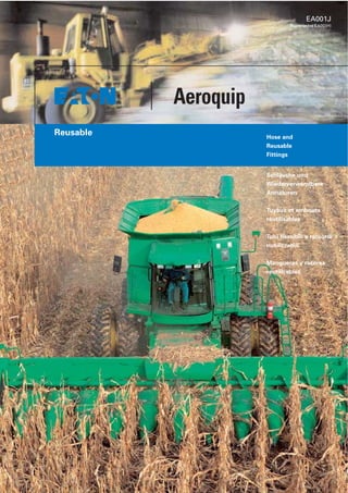
  • 1. EA001J (Supersedes EA001H) Aeroquip Reusable Hose and Reusable Fittings Schläuche und Wiederverwendbare Armaturen Tuyaux et embouts réutilisables Tubi flessibili e raccordi riutilizzabili Mangueras y racores reutilizables
  • 2. Index Inhaltsverzeichnis Table des matières Indice Part Number Index Teilnummernverzeichnis Index alphanumérique des références Indice dei riferimenti Indice de las referencias 4 How to use this catalogue 6 Order Information 9–25 Hose 28–33 Fittings Low Pressure 35 Fittings Low Pressure and Vacuum 38–46 Fittings Medium Pressure 50–56 Fittings High Pressure 60–64 Fittings Super High Pressure 66–75 Accessories 76–84 Technical Information 4 Wie wird mit diesem Katalog gearbeitet? 6 Bestellinformationen 9–25 Schläuche 28–33 Armaturen für Niederdruck 35 Armaturen für Niederdruck und Vakuum 38–46 Armaturen für Mitteldruck 50–56 Armaturen für Hochdruck 60–64 Armaturen für Super-Hochdruck 66–75 Zubehör 76–84 Technische Hinweise 5 Comment utiliser ce catalogue 7 Instructions de commande 9–25 Tuyaux 28–33 Embout basse pression 35 Embout basse pression et tenue au vide 38–46 Embout moyenne pression 50–56 Embout haute pression 60–64 Embout très haute pression 66–75 Accessoires 76–84 Informations techniques 5 Come usare questo catalogo 7 Indicazioni per gli ordini 9–25 Tubi flessibili 28–33 Raccorderia per bassa pressione 35 Raccorderia per bassa pressione e vuoto 38–46 Raccorderia per media pressione 50–56 Raccorderia per alta pressione 60–64 Raccorderia per altissima pressione 66–75 Accessori 76–84 Informazioni techniche 5 Como ha de usarse este catalogo 7 Como efectuar los pedidos 9–25 Mangueras 28–33 Racores para bajas presiones 35 Racores para bajas presiones y vacío 38–46 Racores para medias presiones 50–56 Racores para altas presiones 60–64 Racores para presiones muy elevadas 66–75 Accesorios 76–84 Indicaciones téchnicas Part-No. Page Part-No. Page Part-No. Page Seite Seite Seite Pagina Pagina Pagina FC234 16 FC300 13 FC310 21 FC318 12 FC332 9 FC350 14 FC355 15 G1210 13–19 G1212 13–19 G185261 43 G185264 53 G185265 43 G185287 53 G185296 43 G185297 43 G185299 43 G185302 43 G2401 42 G2411 42 G4007 25 G4010 22, 23 G4013 24, 25 G4103 52, 61 G4202 54 G4614 54, 61 G4645 54 G4675 38 G4677 38 G4679 38 G4690 55, 62 G74446 66 G74453 67 GA10736 46 GA10933 50 GA15063 50 GA15065 39 GA15067 39 GA15069 28 GA15705 28 GA15711 28 GA15772 39 GA17089 20, 21 GA17537 50 GA17544 50 GA17586 50 GC2453 68 GC2542 20, 21 GC3425 67 GC6370 62 GC6374 62 GF9311 11, 12 GH195 22 GH663 20 SH222 24 05.010 9, 10 05.018 66–68 11.002 40 11.003 41 11.005 52, 61 11.006 29 11.011 45 11.013 52 11.020 63 11.021 30 11.027 41 11.030 40 11.031 41 11.045 44 11.057 31 11.072 29 11.074 29 11.122 32 11.139 56, 63 11.140 32 11.143 55 11.144 32 11.187 45 11.327 56 11.340 45 11.390 31 11.391 33 11.420 55, 63 11.421 44 11.721 51, 60 11.839 51, 60 11.840 51, 60 11.841 60 1S-FJ- 35 1S-FL 35 1S-MP- 35 1251 42 1252 44 1503 17 185287 53 23055 69, 70 2412 44 2556 10 26U51B 18 2651 19 2652 19 2661 11 2755 25 2781 23 4202 54 4203 53, 64 4738 30 4797 30, 31 624 72 900564 73 900705 74 900729 71 900952 75 Page Seite Pagina
  • 4. 2 Benefits of Eaton’s Aeroquip Bulk Hose and Reusable Fittings 1. Reduce downtime on equipment when replacement of hose line is required by reusing the fittings with bulk hose. 2. When fitting replacement is necessary, a few fittings with bulk hose provide the ability to assemble any required hose line. 3. All types of equipment can be serviced with the same hose and fitting inventory. 4. Hose assemblies can be made on the job using hand tools. 5. Equipment plumbed with reusable fitting hose assemblies carries a built-in fitting inventory when hose must be replaced. Aeroquip Corporation was founded in 1940 to manufacture and sell a new type of reusable fitting for high pressure hose lines. The idea then, and now, was that a reusable fitting would reduce the cost of replacing hose lines and through its field assembly capability, reduce equipment downtime when a hydraulic hose line needed replacing. It is equally unthinkable to stop a production line or deadline for an expensive piece of con- struction equipment while a hose line is shipped from the factory. Eaton’s Aeroquip also offers a comprehensive range of crimped end fittings to suit a wide selection of Aeroquip hose styles, many of which are detailed in Aeroquip Catalogues EA 005 and EA 011. Furthermore, while sophisticated equipment is available for high volume hose and fitting assembly operations, you can still put Aeroquip fittings and hose together with a few simple hand tools. Eaton’s Aeroquip Schlauch-Meterware und wieder- verwendbare Armaturen bringen Gewinn 1. weil die Stillstandzeiten von Maschinen und Anlagen verkürzt werden, wenn eine defekte Schlauchleitung schnell durch ein Stück neuen Schlauch mit den vorhandenen Armaturen ersetzt wird; 2. weil einige wenige Armaturen und ein paar Meter Schlauch genügen, um jede benötigte Schlauchleitung auch mit neuen Armaturen anzufertigen; 3. weil fast jede Art von hydraulischem Gerät aus dem gleichen kleinen Vorrat von Schlauch- Meterware und Armaturen versorgt werden kann; 4. weil Schlauchleitungen mit einfachem Hand- werkzeug an Ort und Stelle einzubauen sind; 5. weil von Haus aus mit wiederverwendbaren Schlaucharmaturen ausgerüstete Maschinen die für eine etwa zu ersetzende Schlauchleitung benötigten Armaturen gleich mitbringen. Aeroquip Corporation wurde 1940 für die Produktion und den Vertrieb eines neuartigen Typs von wiederverwendbaren Armaturen für Hoch- druckschläuche gegründet. Damals wie heute stand dahinter die Idee, daß eine wiederverwendbare Armatur die Kosten für Schlauchleitungs-Ersatz reduzieren und durch die mögliche Feldmontage überdies die Stillstandzeit von Maschinen verkür- zen muß, wenn eine Leitung auszuwechseln ist. Undenkbar ist es heute, eine Walzstraße anzuhalten oder eine kostspielige Baumaschine stillzulegen, während eine Schlauchleitung vom Herstellerwerk zum Einsatzort – womöglich weit entfernt im Ausland – unterwegs ist. Eaton’s Aeroquip bietet auch eine breite Palette verschiedener Preßarmaturen für eine große An- zahl von Aeroquip Schläuchen an. Viele davon sind in den Katalogen EA 005 und EA 011 mit ihren technischen Daten angeführt. Dennoch weist die wiederverwendbare Eaton’s Aeroquip Schlaucharmatur nach wie vor den wirt- schaftlichsten Weg, Verluste durch den Stillstand teurer Maschinen wegen einer ausgefallenen Lei- tung zu vermeiden. Die Montageeinrichtungen zur Massenproduktion von industriell gefertigten Schlauchleitungen sind im Laufe der Jahre immer vollkommener geworden – Eaton’s Aeroquip Schlauch und wiederverwendbare Armaturen aber können wie eh und je von Hand mit einfachem Werkzeug zu einer zuverlässigen Schlauchleitung zusammengefügt werden. Eaton’s Aeroquip = the Reusable Fitting Concept Eaton’s Aeroquip = Philosophie der wiederver- wendbaren Schlaucharmatur
  • 5. 3 Avantages et bénéfices des embouts réutilisables et tuyaux stockés séparément: 1. Réduction du temps d’immobilisation de l’équipement sur lequel une tuyauterie doit être remplacée. 2. La nouvelle tuyauterie peut être fabriquée sur place avec les anciens embouts et un nouveau morceau de tuyau. 3. Quand les embouts doivent être remplacés, quelques embouts, un peu de tuyau en stock permettent de fabriquer une autre tuyau- terie. 4. Par une standardisation judicieuse sur les équipements ou engins d’un parc donné, un stock réduit de tuyaux et d’embouts consti- tuera la rechange suffisante. 5. Les tuyauteries de remplacement peuvent être faites in situ, sur chantier, dans les ateliers de production. Les machines, les engins équipés de tuyauteries à embouts réutilisable sont partie intégrale du stock d’embouts nécessaire à la rechange ... puis-que les embouts peuvent être réutilisés. La société Aeroquip Corporation fut fondée en 1940 pour la fabrication et la diffusion d’un type entièrement nouveau d’embouts réutilisables. L’idée à l’époque, toujours aussi valable aujour- d’hui d’ailleurs était que l’utilisation d’embouts réutilisables réduirait le coût de la rechange, et, par sa possibilité de montage in situ, réduirait aussi le temps d’immobilisation de l’équipement arrêté par une tuyauterie défaillante. Donc, double économie. Aeroquip propose également une gamme com- plete d’embouts sertis qui se montent avec de nombreux tuyaux dont la plupart sont descrits dans les catalogues EA 005 et EA 011. Et, bien que des équipements très sophistiqués soient disponibles pour le montage en grande série des tuyauteries vous pourrez toujours assembler le tuyau et les embouts réutilisables Aeroquip avec un outillage réduit à deux clés. Benefici e vantaggi dei tubi Eaton’s Aeroquip con raccordi riutilizzabili 1. Riducono il tempo di immobilizzo delle macchine sulle quali si rende necessaria la sostituzione di tubi, permettendo di riutiliz- zare il raccordo su un nuovo tubo flessibile. 2. Una scorta di pochi raccordi e un rotolo di tubo flessibile consentono di realizzare in pochi minuti qualsiasi collegamento caso di necessario ricambio. 3. Ogni tipo di macchina, anche con molti tubi, può avvalersi di una piccola scorta di un solo tipo di tubo e raccordi per ogni urgente eve- nienza. 4. I tubi possono essere assemblati sul posto manualmente, per mezzo di semplici utensili. 5. Le macchine e gli impianti equipaggiati con tubi e raccordi riutilizzabili Aeroquip non hanno necessità di una scorta di raccordi in quanto quelli già montati sulla macchina o sull’impianto possono sempre essere riutiliz- zati. La Aeroquip Corporation fu fondata nel 1940 per la costruzione e la diffusione di un nuovo tipo di raccordo riutilizzabile per tubi flessibili adatti ad alte pressioni. L’idea, valida allora come oggi, era quella che attraverso la riutilizzazione degli stessi raccordi si poteva ridurre il costo dei ricambi dei tubi flessibili ed il tempo di immo- bilizzo di macchine, ferme a causa di tubi difet- tosi, mediante l’assemblaggio del tubo sul posto. Oggi è impensabile da tenere ferma una produ- zione, un impianto o un macchinario, solo per- chè si deve attendere dallo stabilimento di pro- duzione il ricambio di un tubo rotto. Anche se nel corso degli anni la produzione Aeroquip si è estesa ed ha incluso la fabbricazio- ne di tubi con raccordi graffati, che si possono assemblare sul posto, il concetto dei tubi con raccordi riutilizzabili rimane la migliore assicu- razione contro inutili perdite di tempo, causate dalla rottura di tubi per condotta di fluidi. L’Aeroquip dispone anche di una vasta gamma di raccordi di tipo graffato, che possono esere assemblati su molti tubi, descritti in questo catalogo, e su altri, riportati in modo dettagliato nei cataloghi EA 005 ed EA 011. Ventajas del Uso de la Manguera Eaton’s Aero- quip en Rollos y las Conexions Reutilizables 1. Se reduce al mínimo el tiempo que no está trabajando una máquina o un equipo a causa de una manguera dañada. Se repone única- mente el tramo de la manguera, utilizando las mismas conexiones desmontables. 2. Unas cuantas conexiones y unos rollos de manguera proporcionan lo necesario para hacer cualquier línea cuando se necesiten ensambles de repuesto en una emergencia. 3. Se puede dar servicio a todos los tipos de equipo y maquinaria con una mínima existencia de mangueras y conexiones. 4. Se pueden hacer ensambles de mangueras en el taller, en la planta, en el campo o en el sitio que sea, usando solmente herramienta de mano. 5. La maquinaria equipada con ensambles de manguera con las conexiones reutilizables ya lleva las conexiones necesarias y listas para usarse cuando haya que reponer una manguera. Aeroquip Corporation fue fundada en 1940 para fabricar y vender un nuevo tipo de conexiones reutilizables para hacer ensambles de mangue- ras para trabajar a alta presión. La idea en aquel tiempo tanto como hoy en día fue que una cone- xión desarmable y reutilizable reduciría el costo de reposición. Además incorporó la facilidad de poder hacer el ensamble de repuesto en cual- quier sitio, reduciendo así el tiempo que no estaba trabajando un equipo o una máquina por falta de una línea hidráulica. Hoy es igualmente importante evitar paros en una línea de producción industrial o en el uso de equipo para construcción y no tener que es- perar a que llegue del fabricante original una nueva manguera de reposicion. Aeroquip también ofrece una gama completa de racores prensados que se ajustan a la amplis selección de estilos de tuberias Aeroquip, muchos de los cuales están detallados en los catálogos de Aeroquip EA 005 y EA 011. La conexión Aeroquip - desarmable y reutiliza- ble - sigue siendo la mejor forma de evitar que un costoso equipo se quede sin trabajar debido a fallas de mangueras conduciendo cualquier sus- tancia. Aunque hay disponibles máquinas espe- ciales para armar mangueras y conexiones en gran volumen éstas siempre pueden ensamblar- se también en situaciones difíciles utilizando herramienta sencilla de mano. Eaton’s Aeroquip = philosophie de l’embout réutilisable Eaton’s Aeroquip = il Concetto dei Raccordi Riutilizzabili Eaton’s Aeroquip = El Concepto de las Conexiones Desmontables y Reutilizables
  • 6. 4 ˚C ˚C max Max. Op. ˚C Air ˚C max Part No. Op. Press. Max. Op. Press. Min. Burst Press. Min. Bend Rad. Hose ID Hose OD This brochure has been designed to incorporate five languages, English, German, French, Italian and Spanish. For Technical Data, abbreviations, symbols and translations have been used, see de- tailed explanation below. Symbols and Abbreviations Temperature range in degrees celsius Maximum temperature in degrees celsius Maximum operating temperature in degrees celsius Air maximum temperature in degrees celsius Diameter in mm Hexagon size across flats in mm Part Number Operating Pressure in bar Maximum operating pressure in bar Minimum burst pressure in bar Minimum bend radius in mm Hose inside diameter in mm Hose outside diameter in mm Accessories Angle in Degrees Diameter (DN) Dimension Front view Flange For nipples see pages Hose Hose caps must be odered separately Hose cap Hose clamp Letter key a Measure Angle Counter Clockwise Measurement ecc. Metric thread Nipple for hose Page Part number complete with cap Position angle K Socket Standpipe Ø Thread Weight Vacuum in bar Bolt Dieser Katalog enthält fünf Sprachen: Englisch, Deutsch, Französisch, Italienisch und Spanisch. Für die technischen Daten wurden Abkürzungen, Symbole und Übersetzungen ver- wendet. Siehe genaue Erklärungen unten. Symbole und Abkürzungen Temperatur in Grad Celsius Höchsttemperatur in Grad Celsius Maximale Betriebstemperatur in Grad Celsius Maximale Lufttemperatur in Grad Celsius Durchmesser in mm Sechskantgröße in mm (Schlüsselweite) Teilnummer Betriebsdruck in bar Maximaler Betriebsdruck in bar Mindestberstdruck in bar Mindestbiegeradius in mm Schlauch-Innendurchmesser in mm Schlauch-Außendurchmesser in mm Leitungszubehör Verdrehwinkel Nennweite (DN) Maß Vorderansicht Flansch Nippel siehe Seiten Schlauch Schlauchkappen sind getrennt zu bestellen Schlauchkappen Schlauchschellen Buchstaben-Schlüssel a Gegen den Uhrzeigersinn gemessen Vermaßung nach Metrisches Gewinde Nippel für Schlauch Seite Komplette Teilenummer mit Schlauchkappen Verdrehwinkel K Fassung Rohraußendurchmesser Ø Gewinde Gewicht Vakuum in bar Schraube How to use this catalogue? Wie wird mit diesem Katalog gearbeitet?
  • 7. 5 Ce catalogue est rédigé en cinq langues: Anglais, Allemand, Francais, Italien, Espagnol. Des abréviations, symboles et traduction sont utilisés pour les caractéristiques techniques. Voir explication précise ci-après. Symboles et abréviations Température en degrés Celsius Température maximum en degrés Celsius Température maximum de service en degrés Celsius Température maximum d’air en degrés Celsius Diamètre en mm Dimension du six pans sur plats en mm Référence Pression de service en bar Pression maximum de service en bar Pression d’eclatement minimum en bar Rayon de courbure minimum en mm Diamètre intérieur de tuyau en mm Diamètre extérieur de tuyau en mm Accessoires Angle de rotation Diamètre (DN) Dimension Vue de face Bride Pour les nipples voir page Tuyau Les bagues de tuyau doivent être commandées séparément Les bagues de tuyau Collier Code alphabétique a Sens inverse des aiguilles d’une montre Mesure selon la norme Filetage Métrique Nipples pour tuyaux Page Référence complète avec bagues de tuyau integrée Position de l’embout K Jupe Embout lisse Ø Filetage Poids Vide en bar Boulon Questo opuscolo é redatto cinque lingue: ingle- ses, tedesco, francese, italano e spagnolo. Per quanto riguarda i dati tecnici sono stati adottati abbreviazioni, simboli e traduzioni. Al riguardo, si vedano le spiegazioni dettagliate riportate qui di seguito. Simboli et abbreviazioni Temperatura in gradi Celsius Temperatura massima in gradi Celsius Temperatura massima de’esercizio in gradi Celsius Temperatura massima dell’aria in gradi Celsius Diametro in mm Chiave dell’esagono in mm Riferimento Pressione d’esercizio in bar Pressione massima d’esercizio in bar Pressione minimal di scoppio in bar Raggio minimo di curvatura in mm Diametro interno del tubo flessibile in mm Diametro esterno del tubo flessibile in mm Accessori Angolo in gradi Diametro nominale (DN) Dimensioni Vista frontale Flangia Per i raccordi vedere alle pagine Tubo flessibile I tappi di protezione dei tubi devone essere ordinati separatamente I tappi di protezione dei tubi Fascetta Chiave lettera a Misurato antiorario in senso Dimensione normative Filettatura metrica Raccordi per tubi flessibili Pagina Riferimento completo incluso il tappo di protezione Angolo di orientamento K Boccola Tubo Ø Filettatura Peso Vuoto in bar Vite Este catalogo incluye textos en cinco idiomas: inglés, alemán, francés, italiano y español. Para los datos técnicos se emplean abreviaturas, sím- bolos y traducciones. Consultar al respecto las explicaciones dadas a continuación. Símbolos y abreviaturas Temperatura en grados centígrados Temperatura máxima en grados centígrados Temperatura máxima de servicio en grados centígrados Temperatua máxima del aire en grados centígrados Diámetro en mm Tamaño del hexágono entre caras en mm Referencia Presión de servicio en bares Presión máxima de servicio en bares Presión mínima de reventamiento en bares Radio mínimo de curvatura en mm Diámetro interior de la manguera en mm Diámetro exterior de la manguera en mm Accesorios Angulo de giro Diámentro nonimal (DN) Medida, cota o dimensión Vista frontal Brida Para subconjunto ver paginas Manguera Los tapones de tuberia deben pedirse por separado Los tapones de tuberia Abrazaderas Clave alfabética a Medido en sentido contrario a las agujas del reloj Medida según Rosca métrica Manguitos para mangueras Página Referencia complete con tapones Angulo de giro K Casquillo Tubo exterior Ø Roscaa Peso Vacío en bares Tornillo Comment utiliser ce catalogue? Come usare questo catalogo? Cómo ha de usarse este catalogo?
  • 8. 6 Voraussetzung für eine einwandfreie Abwicklung und eine schnelle Lieferung Ihres Auftrages ist die fehlerfreie Iden- tifikation der Teile in Ihrem Auftrag oder Ihrer Anfrage. Aeroquip Teile müssen mit der richtigen Teilenummer, wie sie in diesem Katalog gezeigt wird, bestellt werden. Teil-Nummern und Größen Die Teilnummer steht für Form und Anschluß eines Teiles.Die Größe wird mit einem Bindestrich hinten an- gehängt und gehört verbindlich zur Teilnummer. Die Größenangabe erfolgt in 1/16". Beispiel: 2781-8 = 8/16" = 1 /2" = DN12 Bestellbeispiel: Schlauch-Meterware Länge in m Teil-Nr. 5 0 0 m 2 7 8 1 – 1 2 Bestellbeispiel: Schlauch, abgelängt Stück Teil-Nr. Länge in mm (5-stellig) 5 5 x F C 3 5 0 – 6 – 0 2 5 0 0 Bestellbeispiel: Schlauchleitung Stück Teil-Nr. Länge in mm (5-stellig) 2 5 x 2 7 8 1 – 1 0 – 0 1 7 5 0 2 x Fassung G 4 0 1 0 – 1 0 1 x Nippel 1 1 . 7 2 1 – 2 0 – 1 0 1 x Nippel 1 1 . 8 4 0 – 2 0 – 1 0 oder 3 2 x F C 3 0 0 – 1 2 – 0 1 2 5 0 2 x Fassung G 1 2 1 0 – 1 2 2 x Nippel 1 1 . 0 0 2 – 1 6 – 1 2 Verdrehwinkel von zwei Bogenarmaturen und anderes Schlauchleitungszubehör müssen separat angegeben werden. ACHTUNG: Passende Fassungen für den gewählten Schlauchtyp müssen separat bestellt werden. Die Fas- sungs-Teil-Nummern finden Sie auf den entsprechenden Schlauchseiten. Bestellbeispiel: Fassung Stück Teil-Nr. 1 0 0 0 × G C 2 5 4 2 – 1 0 ACHTUNG: Passende Nippel für den gewählten Schlauch- typ müssen separat bestellt werden. Die Nippel werden ohne Fassung ausgeliefert. Zum Schlauchtyp passende Nip- pel finden Sie auf den beim Schlauch angegebenen Seiten. Bestellbeispiel: Nippel Stück Teil-Nr. 2 5 x 1 1 . 0 7 4 – 4 – 4 Schlauchleitungslänge Die Länge „L“ von Schlauchleitungen wird nach DIN bei Armaturen mit Überwurfmutter bis zum Dichtkopf gemessen. Nach SAE-Norm wird die Länge OA über alles gemessen (over all length). Im Regelfall wird bei der Eaton’s Aeroquip in Europa nach DIN vermaßt und gearbeitet. Sollten Sie Längen nach SAE-Norm benötigen, muß in der Bestellung gesondert darauf hingewiesen werden. Die Schnittlänge „L1“ errechnet sich aus „L“ abzüglich der Summe der Maße „D“ der gewählten Armaturen. Verdrehwinkel Schlauchleitungen mit Krümmer-Anschlüssen an beiden Enden werden i. d. R. so montiert, daß die Krümmer in die gleiche Richtung weisen und miteinander fluchten. Ein etwa erforderlicher Verdrehwinkel „ “ ist deshalb besonders anzugeben. Er wird stets gegen den Uhrzeiger- sinn zwischen den Achsen der Rohrbogen gemessen und beträgt im gezeigten Beispiel = 222°. Bei einer Schlauchleitungsbestellung geben Sie bitte den Winkel hinter der Länge in Grad an. Beispiel: 2781-12-01500-220°. Schlauchschutzüberzüge müssen bei Bestellung mit Län- genangabe des Schutzes angegeben werden. In der Regel wird der Schutz über der ganzen Länge der Schlauchlei- tung angebracht (Länge über alles ≈ Länge L1 in der Abb.). Beispiel: 2781-12-01200 mit 900705-7S über alles. Bestellhinweise Accurate processing and prompt delivery of your order depends on easy identification of your requirements. Please order Aeroquip parts using the correct part num- bers as described in this catalogue. Part numbers and Dash sizes The Part No. describes the shape and connection of a component. Dash size designates the size in 1/16 inch. This number immediately follows the part number and is separated from it with a dash. Example: 2781-8 = 8/16 inch = 1/2 inch Order sample: Bulk hose Qty. in m Part No. 5 0 0 m 2 7 8 1 – 1 2 Order sample: Cut length hose Qty. Part No. Length in mm (5 spaces) 5 5 x F C 3 5 0 – 6 – 0 2 5 0 0 Order sample: Hose assembly components Qty. Part No. Length in mm (5 spaces) 2 5 x 2 7 8 1 – 1 0 – 0 1 7 5 0 2 x Socket G 4 0 1 0 – 1 0 1 x Nipple 1 1 . 7 2 1 – 2 0 – 1 0 1 x Nipple 1 1 . 8 4 0 – 2 0 – 1 0 or 3 2 x F C 3 0 0 – 1 2 – 0 1 2 5 0 2 x Socket G 1 2 1 0 – 1 2 2 x Nipple 1 1 . 0 0 2 – 1 6 – 1 2 Angular relationship of hose lines with elbow connections at both ends must be specified separately. CAUTION: Suitable fittings for a chosen type of hose must be ordered separately. The Part Nos. for the fittings can be found on the pages adjacent to the relevant hoses. Order sample: Socket Qty. Part No. 1 0 0 0 × G C 2 5 4 2 – 1 0 CAUTION: Suitable nipples for a chosen type of hose must also be ordered separately. Nipples are supplied without sockets. Suitable nipples for a given type of hose can be found on the pages specified in the hose description. Order sample: Nipples Qty. Part No. 2 5 x 1 1 . 0 7 4 – 4 – 4 Hose assembly length In accordance with DIN, the hose assembly length “L” is measured on swivel nut fittings to the sealing point. In accordance with the SAE standard, length is measured overall OA. Eaton’s Aeroquip in Europe generally measures and works in accordance with DIN standards. If you require lengths in accordance with the SAE standard, please refer expressly to this in your order. The cut length “L1” is calculated from “L” less the total of the dimensions “D” for the chosen fittings. Angular relationship Hose lines with elbow connections at both ends are gener- ally assembled in such a way that the elbows face in the same direction and are in alignment. Any angular relation- ship required “ ” must therefore be expressly specified. This is always measured counterclockwise between the axis of the elbows and is = 222° in the example shown. When ordering hose lines, please specify the angle in degrees after the length. Example: 2781-12-01500-220°. Protective sheathing for hoses must be specified when ordering, with details of the length required. Sheathing is generally provided for the entire length of the hose line (overall length ≈ length OA1 in illustration). Example: 2781-12-01200 with 900705-75 overall. Order Information Hose assembly length according to SAE Hose assembly length according to DIN EN ISO End View Measure Angle Counter Clockwiese Position angle Angle in Degress At fittings with multiple elbows the rotation angle must be meas- ured at the first elbow on the hose side. Diameter (ND) Diameter (ND) 3 5 6 8 10 12 16 19 25 31 38 51 60 80 90 100 125 Diamètre (ND) Diametro nominale (ND) Diámetro nominal (ND) Letter key Buchstaben-Schlüssel B C E F G H J K M N P R T U S V W Code alphabétique Chiave lettera Clave alfabética
  • 9. La premessa per una corretta evasione del Vostro ordine e per una pronta consegna è la giusta identificazione delle parti nella Vostra richiesta d’ordine. I particolari dell’Aero- quip devono essere ordinati con il numero di riferimento esatto, proprio come viene indicato in questo catalogo. Riferimenti e dimensioni II riferimento descrive la forma e il size di un componente. La dimensione segue il numero dopo una lineetta ed è assolutamente parte integrante del riferimento stesso. Le indicazioni della dimensione sono date in 1/16". Esempio: 2781-8 = 8/16" = 1/2" = DN12 Esempio di ordinaz.: Tubo flessibile al metro Quant. in m Riferimento 5 0 0 m 2 7 8 1 – 1 2 Esempio di ordinaz.: Tubo flessibile, a misura Qant. Riferimento Lunghezza in mm (5 cifre) 5 5 x F C 3 5 0 – 6 – 0 2 5 0 0 Esempio di ordinazione: tubazioni flessibili Qant. Riferimento Lunghezza in mm (5 cifre) 2 5 x 2 7 8 1 – 1 0 – 0 1 7 5 0 2 x Boccola G 4 0 1 0 – 1 0 1 x Raccorde 1 1 . 7 2 1 – 2 0 – 1 0 1 x Raccorde 1 1 . 8 4 0 – 2 0 – 1 0 o 3 2 x F C 3 0 0 – 1 2 – 0 1 2 5 0 2 x Boccola G 1 2 1 0 – 1 2 2 x Raccorde 1 1 . 0 0 2 – 1 6 – 1 2 Gli angoli di orientamento tra due raccordi a curva ed altri accessori delle tubazioni flessibili devono essere indicati separatamente. ATTENZIONE: Le boccole idonee al tipo di tubo flessibile prescelto devono essere ordinate separatamente. I riferimenti delle boccole sono indicati sulle pagine relati- ve al tubo flessibile accanto al tubo flessibile stesso. Esempio di ordinazione: Boccole Qant. Riferimento 1 0 0 0 × G C 2 5 4 2 – 1 0 ATTENZIONE: Anche i raccordi idonei al tipo di tubo fles- sibile prescelto devono essere ordinati separatamente. I raccordi vengono forniti senza boccola. I raccordi idonei ad un certo tipo di tubo flessibile sono indicati alle pagine specifiche, relative al flessibile stesso. Esempio di ordinazione: Raccordo Qant. Riferimento 2 5 x 1 1 . 0 7 4 – 4 – 4 Lunghezza delle tubaz. flessibili La lunghezza «L» delle tubazioni flessibili viene misurata, secondo la normativa DIN, per la raccorderia con dadi girevoli fino alla testa di tenuta, come indicato a destra. Secondo la normativa SAE, la lunghezza viene misurata fuori tutto (vedere il campo sottostante lunghezza OA (overall length). Di regola, I’Aeroquip opera e misura la lunghezza secondo la normativa DIN. Nel caso in cui ne- cessitaste di lunghezze secondo la normativa SAE, dovrete farne espressamente richiesta nella Vostra ordinazione. La lunghezza di taglio «L1» è calcolata dalla «L» detraendo quindi la somma delle dimensioni “D” del raccordo prescelto. Angolo di orientamento Le tubazioni flessibili dotate di raccordi a curva ad entram- be le estremità vengono normalmente montate in modo che le curve siano rivolte nella stessa direzione e siano alli- neate. Un qualsiasi angolo di orientamento desiderato « » deve, perció essere espressamente specificato. Questo è sempre misurato in senso antiorario tra gli assi delle curve e, nell’esempio qui riportato, = 222° (a destra). Nel caso di una ordinazione di tubazioni flessibili, Vi pre- ghiamo di indicare I’angolo in gradi, dopo la lunghezza. Esempio: 2781-12-01500-220°. I rivestimenti di protezione del tubo flessibile, nell’ordina- zione devono essere indicati con i dati relativi alla lung- hezza della protezione stessa. Normalmente, la protezione viene fornita per l’intera lunghezza della tubazione flessibile (lunghezza fuori tutto ≈ Lunghezza L1 nell’illustrazione). Esempio: 2781-12-01200 con 31.001-6S fuori tutto. 7 Instructions de commande Indicazioni per gli ordini Como efectuar los pedidos Une identification correcte et précise de vos besoins garan- tira un traitement rapide de votre commande. Les pièces AEROQUIP doivent être commandées avec la référence précise indiquée dans ce catalogue. Références et modules La référence décrit la forme et le raccordement de chaque pièce. Le module indique la taille exprimée en 1/16 de pouce. II suit immédiatement la référence et en est séparé par un trait d’union. Exemple: 2781-8 = 8/16" = 1 /2" Exemple de commande: tuyau au mètre Long. en m Référence 5 0 0 m 2 7 8 1 – 1 2 Exemple de commande: tuyau coupé à longueur Quantité Référence Long. en mm (5 postions) 5 5 x F C 3 5 0 – 6 – 0 2 5 0 0 Exemple de commande: tuyauterie Quantité Référence Long. en mm (5 postions) 2 5 x 2 7 8 1 – 1 0 – 0 1 7 5 0 2 x Jupe G 4 0 1 0 – 1 0 1 x Nipple 1 1 . 7 2 1 – 2 0 – 1 0 1 x Nipple 1 1 . 8 4 0 – 2 0 – 1 0 ou 3 2 x F C 3 0 0 – 1 2 – 0 1 2 5 0 2 x Jupe G 1 2 1 0 – 1 2 2 x Nipple 1 1 . 0 0 2 – 1 6 – 1 2 Le débattement angulaire d’une tuyauterie équipée de deux embouts coudés doit-étre mentionné séparément. ATTENTION: les jupes appropriées pour le tuyau sélec- tionné doivent être commandées séparément. Leurs réfé- rences se trouvent sur les pages décrivant les tuyaux, immédiatement à côté de ceux-ci. Exemple de commande: jupe Quantité Référence 1 0 0 0 × G C 2 5 4 2 – 1 0 ATTENTION: les nipples convenant pour le tuyau sélec- tionné doivent également être commandés séparément. Les nipples sont livrés sans jupe. Ces nipples se trouvent aux pages indiquées dans la description des tuyaux. Exemple de commande: nipple Quantité Réference. 2 5 x 1 1 . 0 7 4 – 4 – 4 Longueur des tuyauteries Aeroquip utilise la norme DIN pour le calcul de la lon- gueur des tuyauteries. Cette longueur est mesurée au niveau de la surface d’étanchéité, comme indiqué sur le dessin ci-contre (longueur «L»). Selon la norme SAE, la longueur est mesurée hors-tout (longueur «OA»). Veuillez spécifier expressément dans la commande selon quel critère (DIN ou SAE) vous calculez les longueurs. La longueur de coupe «L1» est calculée à partir de «L» moins la cote «D» des embouts sélectionnés. Débattement angulaire Les tuyauteries avec embouts coudés à chaque extrémité sont généralement montées de telle manière que les em- bouts se trouvent dans la même direction et dans le même alignement. C’est pourquoi tout autre angle a requis doit étre indiqué séparément. Cet angle est toujours calculé dans le sens contraire des aiguilles d’une montre entre les axes des coudes. Dans I’exemple mentionné ci-contre, il est de 222°. Pour les commandes de tuyauteries, veuillez indiquer l’angle en degrés derrière la longueur. Exemple: 2781-12-01500-220° Dans le cas de gaines protectrices, il faut indiquer leur lon- gueur lors de la commande. En général, celle-ci est posée sur toute la longueur de la tuyauterie (longueur hors-tout ≈ longueur «L1» sur la figure). Exemple: 2781-12-01200 avec 900705-7S hors-tout. Condición indispensable para una elaboración rápida y sin dificultad de un pedido y suministro del mismo es la iden- tificación sin error de la pieza en su pedido o consulta. Las piezas de Aeroquip hay que pedirlas con el número de refe- rencia correcto, tal como consta en este catálogo. Referencia y dimensión El número de pieza indica la forma y conexión de una pieza. El tamaño se indica a continuación de un guión y está unido inseparablemente a la pieza. El tamaño se da en 1/16" (pulgadas). Ejemplo: 2781-8 = 8/16" = 1/2" = DN12. Ejemplo de pedido: Manguera por metros Longit. en m Referencia 5 0 0 m 2 7 8 1 – 1 2 Ejemplo de pedido: Manguera, cort. a medida Unidades Referencia Longitud en mm (5 cifras) 5 5 x F C 3 5 0 – 6 – 0 2 5 0 0 Ejemplo de pedido: Latiquillo Unidades Referencia Longitud en mm (5 cifras) 2 5 x 2 7 8 1 – 1 0 – 0 1 7 5 0 2 x Abrazad. G 4 0 1 0 – 1 0 1 x Boquilla 1 1 . 7 2 1 – 2 0 – 1 0 1 x Boquilla 1 1 . 8 4 0 – 2 0 – 1 0 o bien 3 2 x F C 3 0 0 – 1 2 – 0 1 2 5 0 2 x Abrazad. G 1 2 1 0 – 1 2 2 x Boquilla 1 1 . 0 0 2 – 1 6 – 1 2 Hay que dar por separado el ángulo de orientación de dos racores curvados, así como otros detalles referentes a los accesorios de latiguillo. ATENCION: Los empalmes adecuados para el tipo de man- guera elegido hay que pedirlos por separado. El número de pieza de empalme lo encontrará Vd. en la página correspondiente a la manguera, al lado de ésta. Ejemplo de pedido: Empalme Unidades Referencia 1 0 0 0 × G C 2 5 4 2 – 1 0 ATENCION: Las boquillas adecuadas a la manguera elegi- da hay que pedirlas también por separado. Las boquillas se suministran sin empalme. Las boquillas apropiadas al tipo de manguera las hallará Vd. en la página indicada para la manguera. Ejemplo de pedido: Boquilla Unidades Referencia 2 5 x 1 1 . 0 7 4 – 4 – 4 Longitud de un latiguillo La longitud “L” del latiguillo con racor hembra loca se mide, de acuerdo con la norma DIN, hasta la cabeza de cierre, como se indica en la figura de la derecha. De acuerdo con la norma SAE, la longitud sería la total incluyendo tuerca (ver la parte de abajo de la longitud “OA”). En Aeroquip se mide y trabaja, en general, de acuer- do con la norma DIN. Si Vd. necesita una longitud según la norma SAE, tiene que indicar esto en el pedido. La lon- gitud de corte “L1” se obtiene al restar de “L” la suma de las cotas “D” del racor elegido. Angulo de giro Latiguillos con racores acodados a ambos extremos se montan por regla general de tal forma, que los codos apuntan en la misma dirección y están alineados entre sí. Así pues es necesario indicar siempre un cierto ángulo de giro “ ”. Este se mide siempre en sentido contrario al movimiento de las agujas del reloj, entre los ejes del tubo de curvatura. En el ejemplo de la figura (a la derecha) tiene el valor de = 222°. Al hacer el pedido de un latiguillo, indicar el ángulo en grados, a continuacibn de la longitud. Ejemplo: 2781-12-O1500-220°. En pedidos para protectores de manguera se debe indicar la longitud del mismo. Normalmente se monta el protector sobre la manguera completa (longitud total ≈ longitud L1 ver croquis). Ejemplo: 2781-12-01200 con 900705-7S sobre todo.
  • 10. Index Hoses Inhalt Schläuche Index Tuyaux Indice Tubo flessibile Contenido Mangueras Page Seite Page Pagina Pagina FC332 2556 2661 FC318 FC300 FC350 FC355 FC234 1503 26U51B 2651/2652 GH663 FC310 GH195 2781 SH222-16 2755 Hose Schlauch Tuyau Tubo flessibile Manguera Hoses – Socketless fittings Schläuche – Socketless Armaturen Tuyaux – Embout Socketless Tubi flessibili – Raccorderia Socketless Mangueras – Racores Socketless Hoses – Fittings Low Pressure and Vacuum Application Schläuche – Niederdruck Armaturen und Vakuum-Anwendung Tuyaux – Embout basse pression et tenue au vide Tubi flessibili – Raccorderia per bassa pressione e vuoto Mangueras – Racores para bajas presiones y vacio Hoses – Fittings Medium Pressure Schläuche – Mitteldruck Armaturen Tuyaux – Embout moyenne pression Tubi flessibili – Raccorderia per media pressione Mangueras – Racores para medias presiones Hoses – Fittings High Pressure Schläuche – Hochdruck Armaturen Tuyaux – Embout haute pression Tubi flessibili – Raccorderia per alta pressione Mangueras – Racores para altas presiones Hose – Fittings Super High Pressure Schlauch – Super-Hochdruck Armaturen Tuyau – Embout très haute pression Tubo flessibile – Raccorderia per altissima pressione Manguera – Racores para presiones muy elevadas 9 10 11 12 13 14 15 16 17 18 19 20 21 22 23 24 25 DIN/SAE Part No. 8
  • 11. Hoses Schläuche Tuyau Tubo flessibili Manguera 9 Specification subject to change without notice FC332 AQP Hose Technical Data: °C = -40 to + 150°C Air* °C max = +121°C Water °C = + 82 °C Technische Daten: °C = -40 bis +150°C Air* °C max = +121°C Water °C = +82 °C Caractéristiques techniques: °C = -40 to + 150°C Air* °C max = +121°C Water °C = + 82 °C Dati tecnici: °C = -40 to + 150°C Air* °C max = +121°C Water °C = + 82 °C Características Técnicas: °C = -40 to + 150°C Air* °C max = +121°C Water °C = + 82 °C Application: Hydraulic systems with petroleum and non-inflammable fluids (HFD, condional), for fuel and lubricating oils, air and water. Anwendung: Für Hydrauliksysteme auf Mineralölbasis und flammwidrigen Medien (HFD bedingt einsetzbar), leichtes Heizöl, Schmieröle, Luft und Wasser Applications: Tuyaux basse pression, perticulièrement conseillés pour les hautes températures, Systèmes hydrauliques à basse de petrole, carburants huile minerales, air et eau. Pour fluides agressifs sous certaines conditions de temperature (HFD). Applicationi: Per circuiti con olii a base minerale e ininfiammabili (HFD, condizionale), benzina, olii lubrificanti, aria ed acqua. Aplicaciones: Sistemas hidráulicos con crudos de petroleo y fluidos propensos a la inflamación (HFD: condicionado), para petróleos de calefacción y aceites de lubricación, aire y agua. Construction: AQP elastomer tube textile braid reinforcement AQP cover Compatibility chart see bulletin EU067 Aufbau: Seele AQP Elastomer Druckträger: Textileinlage Decke AQP Elastomer Beständigkeitsliste siehe Bulletin EG067 Construction: Tube int. en AQP Renforcement: 1 tresse textile Tube ext. en AQP Table de compatibilité voir bulletin EU067 Costruzione: Condotta interna AQP Rinf. costit. da una treccia tess. Rivestim. in AQP de colore azzurro. Compatibilità vedere bollettino EU067 Construcción: Tubo interior de elástica AQP Refuerzo de tejido textil Cubierta ext. de elastóm. AQP Tabla de compatibilidades véase boletin EU067 Part Number ND Hose Size 1/16" I.D. mm O.D. mm Min. Bend Radius mm Max. Oper. Press. bar Burst Press. bar Weight kg Vacuum bar FC332-04 6 –4 6,4 12,4 76 17 70 0,12 FC332-06 10 –6 9,7 16 76 17 70 0,18 FC332-08 12 –8 12,7 19,1 130 17 70 0,22 FC332-10 16 –10 16,0 23,1 150 17 70 0,30 FC332-12 19 –12 19,1 26,4 180 17 70 0,42 Part Number D Ø mm L mm 05.010-4 16 6 05.010-6 20 6 05.010-8 23 6 05.010-10 27 8 05.010-12 30,5 8 05.010 - Size Hose Cap
  • 12. Hoses Schläuche Tuyau Tubo flessibili Manguera 10 Specification subject to change without notice * Rubber covered hose styles for use with gases above 17.5 bar (250 psi) must be perforated. ** These hoses are available in grey, blue, green and red (min. purchased quantity: 1300 m). This hose is also available with a black, textile outer cover, please ask for Part Number 1525-size. * Bei Gasdrücken über 17,5 bar muss die Außendecke perforiert sein. ** Diese Schläuche können in Grau, Blau, Grün und Rot geliefert werden (Mindestabnahme 1300 m). Dieser Schlauch ist auch mit einem schwarzen Garn-Außengeflecht erhältlich. Bitte fragen Sie nach Teilnummer 1525-Größe. * Pour les utilisations avec fluides gazeux à plus de 17,5 bar, la robe exterieur doit être micro-perforée. ** Ces tuyaux sont disponibles en gris, bleu, vert et rouge (Quantité commercialisée: 1300 m). Ce tuyau est aussi disponible avec une couverture textile noire: Reference 1525-module. * Con pressioni di gas superiori a 17,5 bar è necessario perforare il rivistimento esterno. ** Questi tubi sono disponibili nei colori grigio, blue, verde e rosso (Quantità comprata: 1300 m). Questo tube é disponible anche con rivestimento esterno in treccia tessile di colore nero, in tal caso richiederlo con il riferimento 1525-size. * Para presiones superiores a 17,5 bar la cubierta exterior debe estar perforada. ** Estas tuberias estan disponibles en color gris, azul, verde y rojo (Cantidad comprata minimo: 1300 m). Esta tuberia tambien esta disponible con cubierta exterior textil color negro, por favor preguntar for referencia 1525-galga. 2556 Hose Technical Data: °°C = -40°C to +100°C Air* °C max = +71°C Water °C = max = +66°C Technische Daten: °C = -40°C bis +100°C Air* °C max = +71°C Water °C = max = +66°C Caractéristiques techniques: °C = -40°C jusqu à +100°C Air* °C max = +71°C Water °C = max = +66°C Dati tecnici: °C = -40°C to +100°C Air* °C max = +71°C Water °C = max = +66°C Características Técnicas: °C = -40°C to +100°C Air* °C max = +71°C Water °C = max = +66°C Application: Hydraulic systems with petroleum base fluids, fuel and lubricating oils, air* Anwendung: Für Hydrauliksysteme auf Mineralölbasis, leichtes Heizöl, Schmieröle und Luft* Applications: Pour circuits hydrauliques à base d’huiles minérales, fuel, huiles de lubrification et air* Applicationi: Per circuiti idraulici con olii a base minerale, olio combustibile leggero, olii lubrificanti ed aria* Aplicaciones: Para sistemas hidráulicos a base de aceites minerales, fueloil ligero, aceites lubricantes y aire* Construction: Synth. rubber tube NBR Textile: reinforcement Synth. rubber cover CR Compatibility chart see bulletin EU067 Aufbau: Seele synth. Gummi NBR Druckträger: Textileinlage Decke synth. Gummi CR Beständigkeitsliste siehe Bulletin EG067 Construction: Tube int. en NBR 1 tresse textile Tube ext. en CR Table de compatibilité voir bulletin EU067 Costruzione: Condotta interna in NBR Rinforzo con una treccia tessile Rivestim. in gomma sint. CR Compatibilità vedere bollettino EU067 Construcción: Tubo int. de goma sintética NBR Refuerzo de tejido textil Cubierta ext. de goma sint. NBR Tabla de compatibilidades véase boletin EU067 EN854 EN854 EN854 EN854 EN854 Part Number ND Hose Size 1/16" I.D. mm O.D. mm Min. Bend Radius mm Max. Oper. Press. bar Burst Press. bar Weight kg Vacuum bar 2556-4** 6 –4 6,4 12,4 40 25 100 0,10 2556-6** 10 –6 9,7 15,7 70 21 84 0,15 2556-8** 12 –8 12,7 19,1 90 21 84 0,20 2556-10** 16 –10 16,0 23,1 110 17 70 0,28 2556-12** 19 –12 19,0 26,2 150 17 70 0,32 Part Number D Ø mm L mm 05.010-4 16 6 05.010-6 20 6 05.010-8 23 6 05.010-10 27 8 05.010-12 30,5 8 05.010 - Size Hose Cap Typecertification: LNE / NFF16-101 Typenzertifizierung: LNE / NFF16-101 Homologations de type: LNE / NFF16-101 Approvazioni del tipo: LNE / NFF16-101 Certificados: LNE / NFF16-101
  • 13. Hoses Schläuche Tuyau Tubo flessibili Manguera 11 Specification subject to change without notice * Rubber covered hose styles for use with gases above 17,5 bar (250 psi) must be perforated. ** Maximum working pressure for band clamp fittings is 3,5 bar. * Bei Gasdrücken über 17,5 bar muss die Außendecke perforiert sein. ** Maximaler Arbeitsdruck mit Schlauchschellen ist 3,5 bar. * Pour les utilisations avec fluides gazeux à plus de 17,5 bar, la robe exterieur doit être micro-perforée. ** Pressione de service maximum avec colliers: 3,5 bar. * Con pressioni di gas superiori a 17,5 bar è necessario perforare il rivestimento esterno. ** Pressione dinamica d'esercizio con fascetta: 3,5 bar * Para presiones superiores a 17,5 bar la cubierta exterior debe estar perforada. ** La presión de trabajo máxima con abrazaderas de manguera es de 3,5 bar. 2661 AQP Hose Technical Data: °C = -40°C to +150°C Air* °C max = +121°C Technische Daten: °C = -40°C bis +150°C Air* °C max = +121°C Caractéristiques techniques: °C = -40°C jusqu’a +150°C Air* °C max = +121°C Dati tecnici: °C = -40°C to +150°C Air* °C max = +121°C Características Técnicas: °C = -40°C to +150°C Air* °C max = +121°C Application: Suction and transfer applications for petroleum and phosphate ester hydraulic fluids, fuel and lubricating oils, gasoline and water and many other industrial fluids. Anwendung: Für Saug- und Rücklaufleitungen in Hydrauliksystemen auf Mineralölbasis, Phosphatester Flüssigkeiten, leichtes Heizöl und Schmieröle, Benzin, Wasser und andere industrielle Flüssigkeiten. Applications: Aspriation et refoulement basse pression. Pour fluides hydrauliques à base de petrole, et d’esters de phosphate, carburants, lubrificants et eau ainsi que la plupart des fluides industriels. Applicationi: In aspirazione e travaso di olii minerali e di fluidi ininfiammabili (per olii a base di esteri fosforici chiedere all’Aeroquip), benzina, olii lubrificanti, acqua, aria* e molti altri fluidi industriali e prodotti chimici. Aplicaciones: Para conducciones de succión de todos los tipos de sistemas hidrá ulicos, crudos de petróleo, petróleos de calefacción y aceites de lubricación, gasolina, agua. Construction: AQP eslastomer tube reinforcement consisting of a helical wire between an inner and outer textile braid and blue AQP cover Compatibility chart see bulletin EU067 Aufbau: Seele AQP Elastomer, Drahtspirale zwischen einem inneren und einem äußeren Textilgeflecht, abriebfeste, blaue AQP Gummi-Außendecke. Beständigkeitsliste siehe Bulletin EG067 Construction: Tube int. en AQP Renforcement: 1 fil métallique en spriale entre 2 tresses textile Tube ext. en AQP bleu. Table de compatibilité voir bulletin EU067 Costruzione: Condotta interna in AQP Rinf. con uns spirale di acciaio inserita tra 2 trecce tessili Rivestimento in AQP di colore azzurro. Compatibilità vedere bollettino EU067 Construcción: Interior de elastómero AQP, espiral de alambre entre dos trenzas textile cubierta exterior de goma resist. al agritamianio Tabla de compatibilidades véase Boletin EU067 Exceeds SAE 100R4 Exceeds SAE 100R4 Exceeds SAE 100R4 Exceeds SAE 100R4 Exceeds SAE 100R4 Part Number ND Hose Size 1/16" I.D. mm O.D. mm Min. Bend Radius mm Max. Oper. Press. bar Burst Press. bar Weight kg Vacuum bar 2661-12 19 –12 19,1 31,8 127 21** 84 0,62 –0,95 2661-16 25 –16 25,4 38,1 152 17,5** 70 0,74 –0,95 2661-20 31 –20 31,8 45,7 203 14** 56 1,34 –0,95 2661-24 38 –24 38,1 52,3 254 10,5** 42 1,68 –0,95 2661-32 51 –32 50,8 64,8 305 7** 28 1,94 –0,95 2661-40 60 –40 63,5 78,2 356 4,5** 18 2,56 –0,95 2661-48 80 –48 76,2 90,9 457 4** 16 2,92 –0,95 2661-64 100 –64 101,6 119,1 610 3,5** 14 4,59 –0,95 Part Number D Ø mm L mm GF9311-24 GF9311-24 GF9311-24 GF9311-36 GF9311-36 GF9311 - Size Hose Clamp Typecertification: USCG (-12 to -48) Typenzertifizierung: USCG (-12 to -48) Homologations de type: USCG (-12 to -48) Approvazioni del tipo: USCG (-12 to -48) Certificados: USCG (-12 to -48)
  • 14. Hoses Schläuche Tuyau Tubo flessibili Manguera 12 Specification subject to change without notice * Rubber covered hose styles for use with gases above 17,5 bar (250 psi) must be perforated. ** Maximum working pressure for band clamp fittings is 3,5 bar. * Bei Gasdrücken über 17,5 bar muss die Außendecke perforiert sein. ** Maximaler Arbeitsdruck mit Schlauchschellen ist 3,5 bar. * Pour les utilisations avec fluides gazeux à plus de 17,5 bar, la robe exterieur doit être micro-perforée. ** Pressione de service maximum avec colliers: 3,5 bar. * Con pressioni di gas superiori a 17,5 bar è necessario perforare il rivestimento esterno. ** Pressione dinamica d'esercizio con fascetta: 3,5 bar * Para presiones superiores a 17,5 bar la cubierta exterior debe estar perforada. ** La presión de trabajo máxima con abrazaderas de manguera es de 3,5 bar. FC318 Technical Data: °C = -40 to +93°C °C max = +125°C Air* C° max = +70 °C Technische Daten: °C = -40 bis +93°C °C max = +125°C Air* C° max = +70 °C Caractéristiques techniques: °C = -40 jusqu’a +93°C °C max = +125°C Air* C° max = +70 °C Dati tecnici: °C = -40 to +93°C °C max = +125°C Air* C° max = +70 °C Características Técnicas: °C = -40 to +93°C °C max = +125°C Air* C° max = +70 °C Application: Suction and transfer applications for hydraulics, fuel and lubricating oils, gasoline, air* and water. Anwendung: Saug- und Rücklaufleitungen für Hydrauliksysteme auf Mineralölbasis, leichtes Heizöl, Schmieröle, Benzin, Luft* und Wasser. Applications: Aspiration. Pour circuit hydrauliques à base d’huiles minérales, hydrocarbures, huile de graissage, essence, air* et eau. Applicationi: In aspirazione e per travaso di fluido a base di petrolio, benzina e olii lubrificanti, aria* ed acqua. Aplicaciones: Aplicaciones para succión y transmissión para systemas hidrá ulicos, petróleo de calefacción, aceites de lubricatión, gasolina, aire* y agua. Construction: Synthetic rubber tube reinforcement conssisting of a helical wire between an inner and an outer textile braid and synth. rubber cover Compatibility chart see bulletin EU067 Aufbau: Seele synth. Gummi Drahtspirale zwischen einem inneren und einem äußeren Textilgeflecht Decke synth. Gummi Beständigkeitsliste siehe Bulletin EG067 Construction: Tube int. en caout. synth. Renforcement: 1 fil métallique en spirale entre 2 tresses textile Tube ext. caout.synth.Table de compatibilité voir bulletin EU067 Costruzione: Condotta interna in gomma sint. Rinforzo con una spirale di acciaio inserita tra die trecce tessili Rivestimento in gomma sint. Compatibilità vedere bollettino EU067 Construcción: Tubo interior de gomma sintética Refuerzo de alambre en esprial entre un tejido textil interior y otro exterior Cubierta exterior de gomma sintética Tabla de compatibilidades véase boletin EU067 SAE 100R4 SAE 100R4 SAE 100R4 SAE 100R4 SAE 100R4 Part Number ND Hose Size 1/16" I.D. mm O.D. mm Min. Bend Radius mm Max. Oper. Press. bar Burst Press. bar Weight kg Vacuum bar FC318-12 19 –12 19,1 32,1 127 21** 84 0,62 –0,95 FC318-16 25 –16 25,4 38,6 152 17** 70 0,74 –0,95 FC318-20 31 –20 31,8 45,6 203 14** 56 1,34 –0,95 FC318-24 38 –24 38,1 52,8 254 10** 42 1,68 –0,95 FC318-32 51 –32 50,8 64,8 305 7** 28 1,93 –0,95 FC318-40 60 –40 63,4 77,7 356 4** 18 2,56 –0,95 FC318-48 80 –48 76,2 92,5 457 4** 16 2,92 –0,95 FC318-64 100 –64 101,6 119,1 610 3,5** 14 4,6 –0,95 Part Number D Ø mm L mm GF9311-24 GF9311-24 GF9311-24 GF9311-36 GF9311-36 GF9311 - Size Hose Clamp Typecertification: LNE / NFF16-101 (-20 to -24) Typenzertifizierung: LNE / NFF16-101 (-20 bis -24) Homologations de type: LNE / NFF16-101 (-20 to -24) Approvazioni del tipo: LNE / NFF16-101 (-20 to -24) Certificados: LNE / NFF16-101 (-20 to -24)
  • 15. Hoses Schläuche Tuyau Tubo flessibili Manguera 13 Specification subject to change without notice * Rubber covered hose styles for use with gases above 17,5 bar (250 psi) must be perforated * Bei Gasdrücken über 17,5 bar muss die Außendecke perforiert sein. * Pour les utilisations avec fluides gazeux à plus de 17,5 bar, la robe exterieur doit être micro-perforée. * Con pressioni di gas superiori a 17,5 bar è necessario perforare il rivestimento esterno. * Para presiones superiores a 17,5 bar la cubierta exterior debe estar perforada. FC300 AQP Hose Technical Data: °C = -49 to +150°C Air* °C max = +121°C Phosph.-Esth. bas. Fluids max.93°C Technische Daten: °C = -49 bis +150°C Air* °C max = +121°C Phosph.-Esth. bas. Flüssigk. max.93°C Caractéristiques techniques: °C = -49 jusqu’a +150°C Air* °C max = +121°C Phosph.-Esth. bas. Fluids max.93°C Dati tecnici: °C = -49 to +150°C Air* °C max = +121°C Phosph.-Esth. bas. Fluids max.93°C Características Técnicas: °C = -49 to +150°C Air* °C max = +121°C Phosph.-Esth. bas. Fluids max.93°C Application: Hydraulic systems with petroleum base fluids and fire resistant types, fuel and lubricating oils, gasoline, air*, water and other industrial fluids. Anwendung: Für Hydrauliksysteme mit mineralischen und allen nichtbrennbaren Hydraulikflüssigkeiten, für Luft*, Benzin, Rohöl, Dieselöl, Schmieröle und andere industriell verwendete Medien. Applications: Tous fluides hydrauliques et industrieles hautes températ.: huiles miné- rales, hydrocarbures, essences, pétrole brut et dérivés. Pour fluides agres- sifs et esters de phosphate sous certaines cond. de températ. (nous consult.) Applicationi: Per circuiti idraulici con olii a base minerale e ininfiammabili, olii lubrificanti, benzina, aria* ed altri fluidi industriali. Aplicaciones: Sistemas hidráulicos a base de aceites minerales y no inflamables de todas clases, crudos de petróleo, carburantes y aceites de lubricación, gasolina, aire*, agua y otros medios empleados en la industria. Construction: AQP elastomer tube Polyester inner braid single wire braid reinforcement blue polyester braid cover Compatibility chart see bulletin EU067 Aufbau: Seele AQP Elastomer Polyester Innengeflecht Druckträger: 1 Drahtgefl. abriebfestes Polyester-Au- ßengefl., Kennfarbe Blau Beständigkeitsliste siehe Bulletin EG067 Construction: Tube int. en AQP elastomer Tresse int. de polyester. Renforcement: 1 tresse acier. Tube ext. en polyester bleu, réstistant contre l’abrasion. Table de compatibilité voir bulletin EU067 Costruzione: Condotta interna in elastomero (AQP) Rivest.c.u.treccia di poliest. Rinforz.c.u.treccia d’acciaio Rivestimento in poliestere, resistente all’abrasione, colore azzurro Compatibilità vedere bollettino EU067 Construcción: Tubo int. de elastómetro AQP Tejido de poliester Refuerzo de alambre Cubierta ext. de poliester, resistente contra fricción, color azúl Tabla de compatililidades véase boletin EU067 SAE 100R5 SAE 100R5 SAE 100R5 SAE 100R5 SAE 100R5 Part Number ND Hose Size 1/16" I.D. mm O.D. mm Min. Bend Radius mm Max. Oper. Press. bar Burst Press. bar Weight kg Vacuum bar FC300-04 5 –4 4,8 13,2 76 210 840 0,19 FC300-05 6 –5 6,4 14,7 86 210 840 0,24 FC300-06 8 –6 7,9 17,3 102 160 630 0,27 FC300-08 10 –8 10,3 19,6 117 140 560 0,33 FC300-10 12 –10 12,7 23,4 140 125 480 0,49 FC300-12 16 –12 15,9 27,4 165 105 420 0,58 FC300-16 19 –16 22,2 31,2 187 55 225 0,55 FC300-20 25 –20 28,6 38,1 230 45 175 0,68 FC300-24 31 –24 34,9 44,5 267 35 140 0,92 FC300-32 38 –32 46,0 56,4 337 20 85 1,29 FC300-40 60 -40 60,3 73,2 610 24 97 2,13 Part Number L mm HEX mm Weight kg G1210-4 28,0 17 0,025 G1210-5 30,5 19 0,030 G1210-6 33,0 22 0,040 G1210-8 42,0 24 0,055 G1210-10 46,0 30 0,070 G1210-12 53,5 32 0,090 G1212-16 42,0 36 0,105 G1212-20 44,5 46 0,205 G1212-24 47,0 50 0,220 G1212-32 57,2 65 0,430 G1210 - Size G1212 - Size Socket Typecertification: BV / MMM / ABS / GL (-24) / RINA / USCG Typenzertifizierung: BV / MMM / ABS / GL (-24) / RINA / USCG Homologations de type: BV / MMM / ABS / GL (-24) / RINA / USCG Approvazioni del tipo: BV / MMM / ABS / GL (-24) / RINA / USCG Certificados: BV / MMM / ABS / GL (-24) / RINA / USCG
  • 16. Hoses Schläuche Tuyau Tubo flessibili Manguera 14 Specification subject to change without notice * Rubber covered hose styles for use with gases above 17,5 bar (250 psi) must be perforated * Bei Gasdrücken über 17,5 bar muss die Außendecke perforiert sein. * Pour les utilisations avec fluides gazeux à plus de 17,5 bar, la robe exterieur doit être micro-perforée. * Con pressioni di gas superiori a 17,5 bar è necessario perforare il rivestimento esterno. * Para presiones superiores a 17,5 bar la cubierta exterior debe estar perforada. FC350 AQP Hose Technical Data: °C = -49 to +150°C Air* °C max = +121°C Technische Daten: °C = -49 bis +150°C Air* °C max = +121°C Caractéristiques techniques: °C = -49 jusqu’a +150°C Air* °C max = +121°C Dati tecnici: °C = -49 to +150°C Air* °C max = +121°C Características Técnicas: °C = -49 to +150°C Air* °C max = +121°C Application: Air*, gasoline, fuel, lubricating oils and coolants. Anwendung: Druckluft*, Kraftstoff, leichtes Heizöl, Schmierstoffe und Kühlsysteme. Applications: Poids lourds. Air*, carburants, lubrification et refroidissement des moteurs. Applicationi: Nel settore automobilistico e motoristico per combustibili, lubrificanti, olii per cambi automatici, impianti di servosterzo, impianti di raffreddamento, aria compressa ed acqua. Aplicaciones: En la construcción de automóviles y motores, para combustibiles, lubricantes, aceites para cambios automáticos, servodirecciones, sistemas de refrigeración, aire comprimido y agua. Construction: AQP elastomer tube Polyester inner braid single wire braid reinforcement Polyester textile braided cover Compatibility chart see bulletin EU067 Aufbau: Seele AQP Elastomer Polyester-Innengeflecht Druckträger 1 Drahtgeflecht Abriebfestes Polyester Außengeflecht Beständigkeitsliste siehe Bulletin EG067 Construction: Tube int. en AQP 1 tresse polyester Renforcement: 1 tresse métallique Tube ext. en polyester imprégnée Tabla de compatilité voir bulletin EU067 Costruzione: Condotta interna in elastomero (AQP) Rivestita con 1 treccia poliestere Rinforzo con 1 treccia d’acciao Rivestimento in treccia di poliestere Compatibilità vedere bollettino EU067 Construcción: Tubo int. AQP 1 trenza poliester Refuerzo de alambre Cubierta ext. poliester impregnado Tabla de compatibilidades véase boletin EU067 Part Number ND Hose Size 1/16" I.D. mm O.D. mm Min. Bend Radius mm Max. Oper. Press. bar Burst Press. bar Weight kg Vacuum bar FC350-04 5 –4 4,8 13,2 20 138 552 0,19 FC350-05 6 –5 6,4 14,7 25 105 420 0,24 FC350-06 8 –6 7,9 17,3 35 105 420 0,28 FC350-08 10 –8 10,4 19,6 45 85 350 0,33 FC350-10 12 –10 12,7 23,9 60 85 350 0,5 FC350-12 16 –12 15,9 27,4 70 50 210 0,58 FC350-16 19 –16 22,4 31,2 90 25 110 0,55 FC350-20 25 –20 28,7 38,1 115 20 85 0,68 FC350-24 31 –24 35,1 44,5 140 17 70 0,85 Part Number L mm HEX mm Weight kg G1210-4 28,0 17 0,025 G1210-5 30,5 19 0,030 G1210-6 33,0 22 0,040 G1210-8 42,0 24 0,055 G1210-10 46,0 30 0,070 G1210-12 53,5 32 0,090 G1212-16 42,0 36 0,105 G1212-20 44,5 46 0,205 G1212-24 47,0 50 0,220 G1210 - Size G1212 - Size Socket Typecertification: ABS / BV / MED (-04 to -20) / GL / USCG Typenzertifizierung: ABS / BV / MED (-04 to -20) / GL / USCG Homologations de type: ABS / BV / MED (-04 to -20) / GL / USCG Approvazioni del tipo: ABS / BV / MED (-04 to -20) / GL / USCG Certificados: ABS / BV / MED (-04 to -20) / GL / USCG
  • 17. Hoses Schläuche Tuyau Tubo flessibili Manguera 15 Specification subject to change without notice * Rubber covered hose styles for use with gases above 17.5 bar (250 psi) must be perforated. * Bei Gasdrücken über 17,5 bar muss die Außendecke perforiert sein. * Pour les utilisations avec fluides gazeux à plus de 17,5 bar, la robe exterieur doit être micro-perforée. * Con pressioni di gas superiori a 17,5 bar è necessario perforare il rivistimento esterno. * Para presiones superiores a 17,5 bar la cubierta exterior debe estar perforada. FC355 AQP Hose Technical Data: °C = -40 to +150°C Air* °C max = +121°C Technische Daten: °C = -40 bis +150°C Air* °C max = +121°C Caractéristiques techniques: °C = -40 jusqu’a +150°C Air* °C max = +121°C Dati tecnici: °C = -40 to +150°C Air* °C max = +121°C Características Técnicas: °C = -40 to +150°C Air* °C max = +121°C Application: Engine and air brake, for air* gasoline, fuel, lubricating oils and coolants. Anwendung: Im Kraftfahrzeug- und Motorenbau für Kraftstoffe, Schmierstoffe, Automatik-Getriebeöle, Lenkhilfesysteme, Kühlsysteme, Druckluft* und Wasser. Applications: Poids lourds. Air*, carburants, lubrification et refroidissement des moteurs. Excellente résistance à l’abraison. Applicationi: Nel settore automobilistico e motoristico per combustibili, lubrificanti, olii per cambi automatici, impianti di servosterzo, impianti di raffreddamento, aria compressa ed acqua. Aplicaciones: En la construcción de automóviles y motores, para combustibiles, lubricantes, aceites para cambios automáticos, servodirecciones, sistemas de refrigeración, aire comprimido y agua. Construction: AQP elastomer tube Polyester inner braid singel wire braid reinforcement Blue AQP elastomer cover Compatibility chart can see bulletin EU067 Aufbau: Seele AQP Elastomer Polyester-Innengeflecht Druckträger 1 Drahtgeflecht Decke AQP Elastomer blau Beständigkeitsliste siehe Bulletin EG067 Construction: Tube int. en AQP 1 tresse polyester Renforcement: 1 tresse métallique Tube ext. en AQP bleu Table de compatibilité voir bulletin EU067 Costruzione: Condotta interna in elastomero (AQP) Rivestita con 1 treccia poliestere Rinforzo con 1 treccia d’acciao Rivestim. in AQP colore azzurro Compatibilità vedere bollettino EU067 Construcción: Tubo int. AQP 1 trenza poliester Refuerzo de alambre Cubierta ext. de AQP color azul Tabla de compatibilidades véase boletin EU067 Part Number ND Hose Size 1/16" I.D. mm O.D. mm Min. Bend Radius mm Max. Oper. Press. bar Burst Press. bar Weight kg Vacuum bar FC355-04 5 –4 4,8 13,2 20 105 420 0,24 FC355-05 6 –5 6,4 14,7 25 105 420 0,25 FC355-06 8 –6 7,9 17,3 32 105 420 0,34 FC355-08 10 –8 10,4 19,6 45 85 350 0,42 FC355-10 12 –10 12,7 23,9 60 85 350 0,49 FC355-12 16 –12 16 27,4 70 52 210 0,65 FC355-16 19 –16 22,4 31,5 90 28 110 0,68 FC355-20 25 –20 28,7 38,6 115 21 85 0,85 FC355-24 31 –24 35,1 44,5 140 17 70 1,01 FC355-32 38 –32 46 56,4 215 14 56 1,44 Part Number L mm HEX mm Weight kg G1210-4 28,0 17 0,025 G1210-5 30,5 19 0,030 G1210-6 33,0 22 0,040 G1210-8 42,0 24 0,055 G1210-10 46,0 30 0,070 G1210-12 53,5 32 0,090 G1212-16 42,0 36 0,105 G1212-20 44,5 46 0,205 G1212-24 47,0 50 0,220 G1212-32 57,2 65 0,430 G1210 - Size G1212 - Size Socket Typecertification: ABS Typenzertifizierung: ABS Homologations de type: ABS Approvazioni del tipo: ABS Certificados: ABS
  • 18. Hoses Schläuche Tuyau Tubo flessibili Manguera 16 Specification subject to change without notice * Rubber covered hose styles for use with gases above 17,5 bar (250 psi) must be perforated * Bei Gasdrücken über 17,5 bar muss die Außendecke perforiert sein. * Pour les utilisations avec fluides gazeux à plus de 17,5 bar, la robe exterieur doit être micro-perforée. * Con pressioni di gas superiori a 17,5 bar è necessario perforare il rivestimento esterno. * Para presiones superiores a 17,5 bar la cubierta exterior debe estar perforada. FC234 AQP Hose Technical Data: °C = -40 to +150°C Technische Daten: °C = -40 bis +150°C Caractéristiques techniques: °C = -40 jusqu’a +150°C Dati tecnici: °C = -40 to +150°C Características Técnicas: °C = -40 to +150°C Application: Diesel fuel, gasoline,hot lube oil and water Anwendung: Dieselkraftstoff, Benzin, heißes Motorenöl und Wasser Applications: Toutes applications, y compris marine. Haute résistance au feu; robe extérieure auto-extinguible. Applicationi: Combustibile per motori Diesel, benzina, olio motore caldo ed acqua. Aplicaciones: Combustibile Diesel, gasolina, aceites caliente para motores y agua. Construction: AQP elastomer tube brass plated steel wire reinforcement braided refactory insulation blue AQP elastomer cover Compatibility chart see bulletin EU067 Aufbau: Seele AQP Elastomer Druckträger: messingplattiertes Stahlgeflecht, feuerfest isoliert Decke AQP Elastomer blau Beständigkeitsliste siehe Bulletin EG067 Construction: Tube int. en AQP Renforcement à tresse acier plaquée laiton, isolation ignifuge Tube ext. en AQP bleu Table de compatibilité voir bulletin EU067 Costruzione: Condotta interna AQP Rinforzo con treccia d’acciaio placcato in ottone, con isolamento refrattario Rivestim. in AQP di colore azzur Compatibilità vedere bollettino EU067 Construcción: Tubo interior de elástomero AQP Refuerzo de alambre de acero plateado con latón, con aislamiento refractario Cubierta ext. de elastómero AQP Tabla de compatibilidades véase boletin EU067 Part Number ND Hose Size 1/16" I.D. mm O.D. mm Min. Bend Radius mm Max. Oper. Press. bar Burst Press. bar Weight kg Vacuum bar FC234-05 6 –5 6,4 14,7 25 105 414 0,33 FC234-06 8 –6 7,9 17,3 32 105 414 0,42 FC234-08 10 –8 10,4 19,3 44 85 345 0,45 FC234-10 12 –10 12,7 23,9 57 85 345 0,62 FC234-12 16 –12 16 27,4 70 50 207 0,68 FC234-16 19 –16 22,4 31,5 89 28 110 0,68 Part Number L mm HEX mm Weight kg G1210-5 30,5 19 0,030 G1210-6 33,0 22 0,040 G1210-8 42,0 24 0,055 G1210-10 46,0 30 0,070 G1210-12 53,5 32 0,090 G1212-16 42,0 36 0,105 G1210 - Size G1212 - Size Socket Typecertification: ABS / DNV / LR / GL (-05 to -12) / BV / USCG / MED (-08 to -16) Typenzertifizierung: ABS / DNV / LR / GL (-05 to -12) / BV / USCG / MED (-08 to -16) Homologations de type: ABS / DNV / LR / GL (-05 to -12) / BV / USCG / MED (-08 to -16) Approvazioni del tipo: ABS / DNV / LR / GL (-05 to -12) / BV / USCG / MED (-08 to -16) Certificados: ABS / DNV / LR / GL (-05 to -12) / BV / USCG / MED (-08 to -16)
  • 19. Hoses Schläuche Tuyau Tubo flessibili Manguera 17 Specification subject to change without notice * Rubber covered hose styles for use with gases above 17,5 bar (250 psi) must be perforated * Bei Gasdrücken über 17,5 bar muss die Außendecke perforiert sein. * Pour les utilisations avec fluides gazeux à plus de 17,5 bar, la robe exterieur doit être micro-perforée. * Con pressioni di gas superiori a 17,5 bar è necessario perforare il rivestimento esterno. * Para presiones superiores a 17,5 bar la cubierta exterior debe estar perforada. 1503 Technical Data: °C = -40 to +100°C Air* °C max = +71 °C Technische Daten: °C = -40 bis +100°C Air* °C max = +71 °C Caractéristiques techniques: °C = -40 jusqu’a +100 °C Air* °C max = +71 °C Dati tecnici: °C = -40 to +100°C Air* °C max = +71 °C Características Técnicas: °C = -40 to +100°C Air* °C max = +71 °C Application: Hydraulic systems with petroleum, crude, fuel and lubrication oils, gasoline and air*. Anwendung: Hydrauliksysteme auf Mineralölbasis, Rohöl, leichtes Heizöl, Schmieröle, Benzin und Luft*. Applications: Pour circuits hidrauliques à base d’huiles minérals, pétrol brut, hydrocarbures, huiles de graissage, essence et air*. Applicationi: Per circuiti idraulici con olii a base minerale, olio combustibile leggero, olii lubrificanti, benzina ed aria*. Aplicaciones: Para sistemas hidráulicos a base de aceites minerales, crudos de petróleo, fueloil ligero, aceites lubricantes, gasolina y aire*. Construction: Synth. rubber tube textile inner braid, single wire braid reinforcement synthetic rubber impregnated textile cover Compatibility chart see bulletin EU067 Aufbau: Seele aus synth. Gummi Druckträger 1 Garn-/1 Drahtgeflecht Decke imprägniertes Garngeflecht Beständigkeitsliste siehe Bulletin EG067 Construction: Tube int. en caout. synth. Renforcement à 1 tresse textile/1 tresse acier Tube ext. 1 tresse textile imprégnée de caout. synth. Table de compatibilité voir bulletin EU067 Costruzione: Cond. interna in gomma sint. Rinforzo 1 treccia tessile/1 treccia d’acciaio Rivestim. in treccia tessile impregn. Compatibilità vedere bollettino EU067 Construcción: Tubo interior de goma sintética Un tejido textil/1 refuerzo de alambre Cubierta ext. textil impregnada Tabla de compatibilidades véase boletin EU067 SAE 100R5 SAE 100R5 SAE 100R5 SAE 100R5 SAE 100R5 Part Number ND Hose Size 1/16" I.D. mm O.D. mm Min. Bend Radius mm Max. Oper. Press. bar Burst Press. bar Weight kg Vacuum bar 1503-4 5 –4 4,8 13,2 76 210 840 0,19 1503-5 6 –5 6,4 14,7 86 210 840 0,24 1503-6 8 –6 7,9 17,3 102 160 640 0,28 1503-8 10 –8 10,3 19,6 117 140 560 0,33 1503-10 12 –10 12,7 23,4 140 125 490 0,49 1503-12 16 –12 15,9 27,4 165 105 420 0,60 1503-16 19 –16 22,2 31,2 187 55 220 0,57 1503-20 25 –20 28,6 38,1 229 45 180 0,68 1503-24 31 –24 34,9 44,5 267 35 140 0,85 1503-32 38 –32 46,0 56,6 337 25 100 1,24 1503-32 51 –32 46,0 56,6 337 25 100 1,24 1503-40 60 –40 60,3 73,2 610 25 100 2,14 Part Number L mm HEX mm Weight kg G1210-4 28,0 17 0,025 G1210-5 30,5 19 0,030 G1210-6 33,0 22 0,040 G1210-8 42,0 24 0,055 G1210-10 46,0 30 0,070 G1210-12 53,5 32 0,090 G1212-16 42,0 36 0,105 G1212-20 44,5 46 0,205 G1212-24 47,0 50 0,220 G1212-32 57,2 65 0,430 G1212-32 57,2 65 0,430 G1212-40 63,5 85 0,925 G1210 - Size G1212 - Size Socket Typecertification: USCG (-4 to -32) Typenzertifizierung: USCG (-4 to -32) Homologations de type: USCG (-4 to -32) Approvazioni del tipo: USCG (-4 to -32) Certificados: USCG (-4 to -32)
  • 20. Hoses Schläuche Tuyau Tubo flessibili Manguera 18 Specification subject to change without notice 26U51B Technical Data: °C = -40 bis +120°C Technische Daten: °C = -40 bis +120°C Caractéristiques techniques: °C = -40 bis +120°C Dati tecnici: °C = -40 bis +120°C Características Técnicas: °C = -40 bis +120°C Application: Transport of Liqiuid Petroleum Gas ( LPG). Anwendung: Transport von Flüssiggas (LPG). Applications: Transport du gaz liquide de pétrole (LPG). Applicationi: Transporto del gas liquido del petrolio (LPG). Aplicaciones: Transporte del gas liquido del petróleo (LPG). Construction: Synth.rubber tube 1-textile, 1-wire braid reinforcement (stainl. steel). Perfor. EPDM cover and polyethylene layer (BRUISER). Aufbau: Seele aus synth.Gummi Druckträger: 1-Garn, 1-Drahtgeflecht (rostfr.Stahl). Perf. EPDM Decke und Polyethylen-Schutzfolie (BRUISER). Construction: Tube int. en caout.synth. renforcement à 1 tresse textile, 1 tresse acier (inoxidable). Tube ext. en caout. synth. resistant à l’abrasion et couche de polyéthylène (BRUISER). Costruzione: Cond.interna in gomma sint. Rinforzo 1 trecce tessile, 1 trecce d’acciaio (inossidabile). Rivestim. In gomma sint. resistente all’abrasione e strato del polietilene (BRUISER). Construcción: Tubo interior de goma sintética 1 tejido textil, 1 refuerzo de al ambre (inoxidable). Cubierta ext. De goma sintética resistente contra fricción y capa del polietileno (BRUISER). Part Number ND Hose Size 1/16" I.D. mm O.D. mm Min. Bend Radius mm Max. Oper. Press. bar Burst Press. bar Weight kg Vacuum bar 26U51B-8 10 –8 10,3 19,5 120 25 560 26U51B-12 16 –12 15,9 27,4 165 25 420 26U51B-16 19 –16 22,2 31,3 190 25 220 26U51B-20 25 –20 28,6 38,1 230 25 175 26U51B-24 31 –24 34,9 44,5 270 25 140 Part Number L mm HEX mm Weight kg G1210-8 42,0 24 0,055 G1210-12 53,5 32 0,090 G1212-16 42,0 36 0,105 G1212-20 44,5 46 0,205 G1212-24 47,0 50 0,220 G1210 - Size G1212 - Size Socket
  • 21. Hoses Schläuche Tuyau Tubo flessibili Manguera 19 Specification subject to change without notice * Rubber covered hose styles for use with gases above 17.5 bar (250 psi) must be perforated. * Bei Gasdrücken über 17,5 bar muss die Außendecke perforiert sein. * Pour les utilisations avec fluides gazeux à plus de 17,5 bar, la robe exterieur doit être micro-perforée. * Con pressioni di gas superiori a 17,5 bar è necessario perforare il rivistimento esterno. * Para presiones superiores a 17,5 bar la cubierta exterior debe estar perforada. 2651 / 2652 Technical Data: °C = -40 to +100°C °C max = +120 °C Air* °C max = +71°C Technische Daten: °C = -40 bis +100°C °C max = +120 °C Air* °C max = +71°C Caractéristiques techniques: °C = -40 jusqu’a +100 °C °C max = +120 °C Air* °C max = +71 °C Dati tecnici: °C = -40 to +100 °C °C max = +120 °C Air* °C max = +71 °C Características Técnicas: °C = -40 to +100°C °C max = +120 °C Air* °C max = +71°C Application: Hydraulic systems with petroleum, crude, fuel and lubrication oils, air* and water. Anwendung: Hydrauliksysteme auf Mineralölbasis, Rohöl, leichtes Heizöl, Schmieröle, Luft* und Wasser Applications: Pour circuits hidrauliques à base d’huiles minérales, pétrol brut, hydrocarbures, huiles de graissage, air* et eau. Applicationi: Per circuiti idraulici con olii a base minerale, olio combustibile leggero, olii lubrificanti, aria* e acqua. Aplicaciones: Para sistemas hidráulicos a base de aceites minerales, crudos de petróleo, fueloil ligero, aceites lubricantes, aire* y agua. Construction: Synth. rubber tube 2-textile, 1-wire braid reinforcement abrasion-resistant rubber cover Compatibility chart see bulletin EU067 Aufbau: Seele aus synth. Gummi Druckträger 2-Garn-/1 Drahtgeflecht Decke abriebfestes Gummi Beständigkeitsliste siehe Bulletin EG067 Construction: Tube int. en caout. synth. Renforcement à 2 tresses textile/1 tresse acier Tube ext. en caout. synth. résistant à l’abrasion. Table de compatibilité voir bulletin EU067 Costruzione: Cond. interna in gomma sint. Rinforzo 2 trecce tessile/1 treccia d’acciaio Rivestim. in gomma sint. resistente all’abrasione Compatiblità vedere bollettino EU067 Construcción: Tubo interior de goma sintética Dos tejidos textil/1 refuerzo de alambre Cubierta ext. de goma sintética resistente contra fricción Tabla de compatibilidades véase boletin EU067 Part Number ND Hose Size 1/16" I.D. mm O.D. mm Min. Bend Radius mm Max. Oper. Press. bar Burst Press. bar Weight kg Vacuum bar 2651-4 5 –4 4,8 13,7 76 210 840 0,24 2651-5 6 –5 6,4 14,7 86 210 840 0,25 2651-6 8 –6 7,9 17,3 102 155 630 0,36 2651-8 10 –8 10,4 19,6 117 140 560 0,40 2651-10 12 –10 12,7 23,4 140 125 490 0,57 2651-12 16 –12 16 27,4 165 105 420 0,70 2651-16 19 –16 22,4 31,2 187 55 225 0,65 2651-20 25 –20 28,7 38,1 229 45 175 0,85 2651-24 31 –24 35,1 44,5 267 35 140 1,01 2651-32 38/51 –32 46 56,4 337 25 100 1,31 2651-40 60 –40 60,5 73,2 610 25 100 2,23 2652-48 80 –48 76,2 91,3 840 14 55 3,18 Part Number L mm HEX mm Weight kg G1210-4 28,0 17 0,025 G1210-5 30,5 19 0,030 G1210-6 33,0 22 0,040 G1210-8 42,0 24 0,055 G1210-10 46,0 30 0,070 G1210-12 53,5 32 0,090 G1212-16 42,0 36 0,105 G1212-20 44,5 46 0,205 G1212-24 47,0 50 0,220 G1212-32 57,2 65 0,430 G1212-40 63,5 85 0,925 G1212-48 63,5 100 1,090 G1210 - Size G1212 - Size Socket Typecertification: 2651: ABS / RST / LR (-6 to -40) 2652: GL / LR / MED / RINA Typenzertifizierung: 2651: ABS / RST / LR (-6 to -40) 2652: GL / LR / MED / RINA Homologations de type: 2651: ABS / RST / LR (-6 to -40) 2652: GL / LR / MED / RINA Approvazioni del tipo: 2651: ABS / RST / LR (-6 to -40) 2652: GL / LR / MED / RINA Certificados: 2651: ABS / RST / LR (-6 to -40) 2652: GL / LR / MED / RINA
  • 22. Hoses Schläuche Tuyau Tubo flessibili Manguera 20 Specification subject to change without notice * Rubber covered hose styles for use with gases above 17.5 bar (250 psi) must be perforated. * Bei Gasdrücken über 17,5 bar muss die Außendecke perforiert sein. * Pour les utilisations avec fluides gazeux à plus de 17,5 bar, la robe exterieur doit être micro-perforée. * Con pressioni di gas superiori a 17,5 bar è necessario perforare il rivistimento esterno. * Para presiones superiores a 17,5 bar la cubierta exterior debe estar perforada. GH663 Technical Data: °C = -40 to +100°C °C max = +125°C Air* °C max = +70°C Technische Daten: °C = -40 bis +100°C °C max = +125°C Air* °C max = +70°C Caractéristiques techniques: °C = -40 jusqu’a +100 °C °C max = +125 °C Air* °C max = +70 °C Dati tecnici: °C = -40 to +100 °C °C max = +125 °C Air* °C max = +70 °C Características Técnicas: °C = -40 to +100 °C °C max = +125 °C Air* °C max = +70 °C Application: Hydraulic systems with petroleum base fluids, fuel and lubricating oils, air*. Anwendung: Für Hydrauliksysteme auf Mineralölbasis, leichtes Heizöl, Schmieröle, und Luft*. Applications: Pour circuits hydrauliques à base d’huiles minérales, fuel, huiles de lubrification et air*. Applicationi: Per circuiti idraulici con olii a base minerale, olio combustibilie leggero olii lubrificanti ed aria*. Aplicaciones: Para sistemas hidráulicos a base de aceites minerales, fueloil ligero, aceites lubricantes y aire*. Construction: Synth. NBR rubber tube 1-wire braid reinforcement Synth. CR rubber cover Compatibility chart see bulletin EU067 Aufbau: Seele synth. Gummi NBR Druckträger: 1 Drahtgeflecht Decke synth. Gummi CR Beständigkeitsliste siehe Bulletin EG067 Construction: Tube int. en NBR Renforcement: 1 tresse acier Tube ext. en CR Table de compatibilitévoir bulletin EU067 Costruzione: Condotta interna in NBR Rinf. con una treccia d’acciaio Rivestim. in gomma sint. Compatibilità vedere EU067 Construcción: Tubo int. de goma sintética NBR Refuerzo de alambre Cubierta ext. de gomma sint. CR Tabla de compatibilidades véase boletin EU067 EN853 Exceeds SAE 100R1AT EN853 Exceeds SAE 100R1AT EN853 Exceeds SAE 100R1AT EN853 Exceeds SAE 100R1AT EN853 Exceeds SAE 100R1AT Part Number ND Hose Size 1/16" I.D. mm O.D. mm Min. Bend Radius mm Max. Oper. Press. bar Burst Press. bar Weight kg Vacuum bar GH663-4 6 –4 6,4 13,4 100 225 900 0,22 GH663-5 8 –5 7,9 15 115 225 900 0,27 GH663-6 10 –6 9,5 17,4 130 210 840 0,33 GH663-8 12 –8 12,7 20,6 180 175 700 0,44 GH663-10 16 –10 15,9 23,7 200 140 560 0,52 GH663-12 19 –12 19 27,7 240 125 500 0,64 GH663-16 25 –16 25,4 35,6 300 90 360 0,80 Part Number L mm HEX mm Weight kg GC2542-04 40,4 19 0,038 GA17089-5 34 22 0,042 GC2542-06 47 24 0,075 GC2542-08 50,5 27 0,095 GC2542-10 51 30 0,115 GC2542-12 61,2 36 0,195 GC2542-16 71 46 0,250 GC2542 - Size GA17089 - Size Socket No Skive Typecertification: ABS / BV / DNV / GL / USCG / BWB Typenzertifizierung: ABS / BV / DNV / GL / USCG / BWB Homologations de type: ABS / BV / DNV / GL / USCG / BWB Approvazioni del tipo: ABS / BV / DNV / GL / USCG / BWB Certificados: ABS / BV / DNV / GL / USCG / BWB IMPORTANT! Hose size -5, use nipple size -6! Wichtig: Schlauchgröße -5, bitte Nippel -6 verwenden. IMPORTANT! Module tuyan -5, utiliser les nipples module -6! IMPORTANTE! Tubi size -5, usare nipple -6! IMPORTANTE! Galga de manguera -5, usare racor galga -6!
  • 23. Hoses Schläuche Tuyau Tubo flessibili Manguera 21 Specification subject to change without notice * Rubber covered hose styles for use with gases above 17,5 bar (250 psi) must be perforated * Bei Gasdrücken über 17,5 bar muss die Außendecke perforiert sein. * Pour les utilisations avec fluides gazeux à plus de 17,5 bar, la robe exterieur doit être micro-perforée. * Con pressioni di gas superiori a 17,5 bar è necessario perforare il rivestimento esterno. * Para presiones superiores a 17,5 bar la cubierta exterior debe estar perforada. FC310 Hi-Pac Hose Technical Data: -40 to +100°C °C max = +120°C Air* °C max = +70°C Technische Daten: Temperaturbereich: -40 bis +100°C °C max = +120°C Air* °C max = +70°C Caractéristiques techniques: -40 à +100 °C °C max = +120 °C Air* °C max = +70 °C Dati tecnici: -40 a +100 °C °C max = +120 °C Air* °C max = +70 °C Características Técnicas: -40 hasta +100 °C °C max = +120 °C Air* °C = +70 °C Application: Hydraulic systems with petroleum, for fuel and lubricating oils and air* Anwendung: Für Hydrauliksysteme auf Mineralölbasis, leichtes Heizöl, Schmieröle und Luft* Applications: Pour circuits hydrauliques à base d’huiles minérales, fuel, huiles de lubrification et air* Applicationi: Per circuiti idraulici con olii a base minerale, olio combustibile leggero, olii lubrificanti ed aria* Aplicaciones: Para sistemas hidráulicos a base de aceites minerales, fueloil ligero, aceites lubricantes y aire* Construction: Synth. NBR rubber tube Hi-Pac wire braid reinforcement Synth. CR rubber cover Compatibility chart see bulletin EU067 Aufbau: Seele synth. Gummi NBR Druckträger Hi-Pac Drahtgeflecht Decke synth. Gummi CR Beständigkeitsliste siehe Bulletin EG067 Construction: Tube int. en NBR Renforcement à tresse acier Hi-Pac Tube ext. en CR Table de compatibilité voir bulletin EU067 Costruzione: Condotta interna in NBR Rinf. con una treccia d’acciaio Hi-Pac Rivestim. in gomma sint. CR Compatibilità vedere bollettino EU067 Construcción: Tubo int. de goma sintética NBR Refuerzo de alambre Hi-Pac Cubierta ext. de goma sint. CR Tabla de compatibilidades véase boletin EU067 SAE 100R2 Performance SAE 100R2 Performance SAE 100R2 Performance SAE 100R2 Performance SAE 100R2 Performance Part Number ND Hose Size 1/16" I.D. mm O.D. mm Min. Bend Radius mm Max. Oper. Press. bar Burst Press. bar Weight kg Vacuum bar FC310-03 5 –3 4,8 12 45 350 1400 0,23 FC310-04 6 –4 6,4 14 50 350 1400 0,31 FC310-05 8 –5 7,9 15 60 300 1200 0,32 FC310-06 10 –6 9,5 17 65 280 1120 0,38 FC310-08 12 –8 12,7 20 90 240 960 0,50 FC310-10 16 –10 15,9 24 100 190 760 0,64 FC310-12 19 –12 19 27 120 155 620 0,77 FC310-16 25 –16 25,4 34 150 140 560 1,05 Part Number L mm HEX mm Weight kg GC2542-04 40,4 19 0,038 GA17089-5 34 22 0,042 GC2542-06 47 24 0,075 GC2542-08 50,5 27 0,095 GC2542-10 51 30 0,115 GC2542-12 61,2 36 0,195 GA17089-1671 41 0,217 GC2542 - Size GA17089 - Size Socket No Skive Typecertification: ABS / LNE/NFF16-101 / GL / LOBA / USCG Typenzertifizierung: ABS / LNE/NFF16-101 / GL / LOBA / USCG Homologations de type: ABS / LNE/NFF16-101 / GL / LOBA / USCG Approvazioni del tipo: ABS / LNE/NFF16-101 / GL / LOBA / USCG Certificados: ABS / LNE/NFF16-101 / GL / LOBA / USCG
  • 24. Hoses Schläuche Tuyau Tubo flessibili Manguera 22 Specification subject to change without notice * Rubber covered hose styles for use with gases above 17,5 bar (250 psi) must be perforated * Bei Gasdrücken über 17,5 bar muss die Außendecke perforiert sein. * Pour les utilisations avec fluides gazeux à plus de 17,5 bar, la robe exterieur doit être micro-perforée. * Con pressioni di gas superiori a 17,5 bar è necessario perforare il rivestimento esterno. * Para presiones superiores a 17,5 bar la cubierta exterior debe estar perforada. GH195 MatchMate Blue Technical Data: -40°C to +150°C Technische Daten: Temperaturbereich: -40°C bis +150°C Caractéristiques techniques: -40°C à +150°C Dati tecnici: -40°C a +150°C Características Técnicas: -40°C hasta +150°C Application: Hydraulic system service with petroleum, fireresistant and water-base fluids, fuel and lubricating systems. Anwendung: Hydrauliksysteme mit mineralischen und nichtbrennbaren Hydraulikflüssigkeiten, Wasser-Gemische, Benzin und Schmiersysteme. Applications: Circuits hydrauliques avec fluides à base de pétrole, fluides résistant au feu, fluides à base d’eau, combustibles et lubrifiants. Applicationi: Sistemi idraulici con olii minerali, olii ininfiammabili e fluidi miscelati con acqua, carburanti e lubrificanti. Aplicaciones: Para sistemas hidráulicas ad alta presión que operen con fluidos a base de petróleo y tipos industriales restentes al fuego. Construction: AQP elastomer tube Reinforcement double wire braid, Blue AQP cover. Aufbau: Seele AQP Elastomer Druckträger 2-Drahtgeflecht, Decke AQP blau Construction: Tube int. en AQP Renforcement: 2 tresses acier, Tube ext. en AQP bleu. Costruzione: Condotta interna in AQP Rinforzo con 2 trecce d’acciao, Rivestim. in AQP colore azzurro. Construcción: Tube int. AQP, Refuerzo de trenza doble de alambre, Cubierta ext. de AQP color azul. Exceeds SAE 100R2AT Exceeds SAE 100R2AT Exceeds SAE 100R2AT Exceeds SAE 100R2AT Exceeds SAE 100R2AT Part Number ND Hose Size 1/16" I.D. mm O.D. mm Min. Bend Radius mm Max. Oper. Press. bar Burst Press. bar Weight kg Vacuum bar GH195-4 6 –4 6,4 15,1 100 400 1600 0,40 GH195-6 10 –6 9,5 19,2 125 345 1380 0,58 GH195-8 12 –8 12,7 22,1 180 290 1170 0,684 GH195-10 16 –10 15,9 25,1 200 225 900 0,80 GH195-12 19 –12 19,0 29,5 240 210 830 1,00 GH195-16 25 –16 25,4 37,8 305 170 690 1,44 GH195-20 31 –20 31,8 48,8 420 155 620 2,381 GH195-24 38 –24 38,1 55,1 510 120 485 2,59 GH195-32 51 –32 50,8 67,8 635 100 415 3,38 Part Number L mm HEX mm Weight kg G4010-4 44 22 0,075 G4010-6.1 49 27 0,110 G4010-8 51 30 0,150 G4010-10 53,5 32 0,150 G4010-12 62,7 38 0,250 G4013-16 75 46 0,420 G4010-20 87 60 0,710 G4010-24 84,7 65 0,825 G4010-32 94 80 1,440 G4010 - Size G4013 - Size Socket Typecertification: ABS / RST Typenzertifizierung: ABS / RST Homologations de type: ABS / RST Approvazioni del tipo: ABS / RST Certificados: ABS / RST
  • 25. Hoses Schläuche Tuyau Tubo flessibili Manguera 23 Specification subject to change without notice * Rubber covered hose styles for use with gases above 17,5 bar (250 psi) must be perforated * Bei Gasdrücken über 17,5 bar muss die Außendecke perforiert sein. * Pour les utilisations avec fluides gazeux à plus de 17,5 bar, la robe exterieur doit être micro-perforée. * Con pressioni di gas superiori a 17,5 bar è necessario perforare il rivestimento esterno. * Para presiones superiores a 17,5 bar la cubierta exterior debe estar perforada. 2781 2ST Technical Data: -40 to +100°C °C max = +125°C Air* °C max = +70°C Technische Daten: Temperaturbereich: -40 bis +100°C °C max = +125°C Air* °C max = +70°C Caractéristiques techniques: -40 à +100°C °C max = +125°C Air* °C max = +70°C Dati tecnici: -40 a +100°C °C max = +125°C Air* °C max = +70°C Características Técnicas: -40 hasta +100°C °C max = +125°C Air* °C max = +70°C Application: High pressure hydraulic systems with petroleum, for fuel and lubricating oils and air* Anwendung: Hochdruck-Hydrauliksysteme auf Mineralölbasis, leichtes Heizöl, Schmieröle und Luft* Applications: Pour circuits hydrauliques haute pression à base d’huiles minérales, fuel, huiles de lubrification et air* Applicationi: Circuiti idraulici ad alta pressione con olii a base minerale, olio combustibile leggero, olii lubrificanti ed aria* Aplicaciones: Sistemas hidráulicos de alta presión a base de aceites minerals, fueloil ligero, aceites lubricantes y aire* Construction: Synth. NBR rubber tube 2 wire braid reinforcement Synth. CR rubber cover Compatibility chart see bulletin EU067 Aufbau: Seele synth. Gummi NBR Druckträger 2 Drahtgeflechte Decke synth. Gummi CR Beständigkeitsliste siehe Bulletin EG067 Construction: Tube int. en NBR Renforcement 2 tresses acier Tube ext. en CR Table de compatibilité voir bulletin EU067 Costruzione: Condotta interna in NBR Rinf. con due trecce d’acciaio Rivestimento in gomma sint. CR Compatibilità vedere bollettino EU067 Construcción: Tubo int. de goma sint. NBR Dos refuerzos de alambre Cubierta ext. de goma sint. CR Tabla de compatibilidades véase boletin EU067 EN853 Exceeds SAE 100R2A EN853 Exceeds SAE 100R2A EN853 Exceeds SAE 100R2A EN853 Exceeds SAE 100R2A EN853 Exceeds SAE 100R2A Part Number ND Hose Size 1/16" I.D. mm O.D. mm Min. Bend Radius mm Max. Oper. Press. bar Burst Press. bar Weight kg Vacuum bar 2781-4 6 –4 6,4 17,5 100 400 1600 0,45 2781-6 10 –6 9,5 21,4 130 345 1380 0,60 2781-8 12 –8 12,7 24,6 180 295 1180 0,75 2781-10 16 –10 15,9 27,8 200 250 1000 0,85 2781-12 19 –12 19 31,8 240 215 860 1,10 2781-16 25 –16 25,4 39,7 300 175 700 1,50 2781-20 31 –20 31,8 50,8 420 155 620 2,40 2781-24 38 –24 38,1 57,2 500 125 500 3,00 2781-32 51 –32 50,8 69,8 630 90 360 3,55 Part Number L mm HEX mm Weight kg G4010-4 44 22 0,075 G4010-6.1 49 27 0,110 G4010-8 51 30 0,150 G4010-10 53,5 32 0,150 G4010-12 62,7 38 0,250 G4013-16 75 46 0,420 G4010-20 87 60 0,710 G4010-24 84,8 65 0,825 G4010-32 94 80 1,440 G4010 - Size G4013 - Size Socket Typecertification: ABS / BV / LR / MED / MMM Typenzertifizierung: ABS / BV / LR / MED / MMM Homologations de type: ABS / BV / LR / MED / MMM Approvazioni del tipo: ABS / BV / LR / MED / MMM Certificados: ABS / BV / LR / MED / MMM
  • 26. SH222 Hoses Schläuche Tuyau Tubo flessibili Manguera 24 Specification subject to change without notice * Rubber covered hose styles for use with gases above 17,5 bar (250 psi) must be perforated * Bei Gasdrücken über 17,5 bar muss die Außendecke perforiert sein. * Pour les utilisations avec fluides gazeux à plus de 17,5 bar, la robe exterieur doit être micro-perforée. * Con pressioni di gas superiori a 17,5 bar è necessario perforare il rivestimento esterno. * Para presiones superiores a 17,5 bar la cubierta exterior debe estar perforada. SH222 2ST Technical Data: -40 to +100°C °C max = +125°C Technische Daten: Temperaturbereich: -40 bis +100°C °C max = +125°C Caractéristiques techniques: -40 à +100°C °C max = +125°C Dati tecnici: -40 a +100°C °C max = +125°C Características Técnicas: -40 hasta +100°C °C max = +125°C Application: High pressure hydraulic systems with petroleum and for lubrificating oils Anwendung: Hochdruck-Hydrauliksysteme auf Mineralölbasis und Schmieröle Applications: Pour circuits hydrauliques haute pression à base d’huiles minérales et huiles de lubrification Applicationi: Circuiti idraulici ad alta pressione con olii a base minerale ed olii lubrificanti Aplicaciones: Sistemas hidráulicos de alta presión a base de aceites minerals y aceites lubrificantes Construction: Synth. NBR rubber tube 2 wire braid reinforcement Synth. CR rubber cover Aufbau: Seele synth. Gummi NBR Druckträger 2 Drahtgeflechte Decke synth. Gummi CR Construction: Tube int. en NBR Renforcement 2 tresses acier Tube ext. en CR Costruzione: Condotta interna in NBR Rinf. con due trecce d’acciaio Rivestimento in gomma sint. CR Construcción: Tubo int. de goma sint. NBR Dos refuerzos de alambre Cubierta ext. de goma sint. CR EN853 EN853 EN853 EN853 EN853 Part Number ND Hose Size 1/16" I.D. mm O.D. mm Min. Bend Radius mm Max. Oper. Press. bar Burst Press. bar Weight kg Vacuum bar SH222-16 25 –16 25,4 38,3 300 210 840 Part Number L mm HEX mm Weight kg G4013-16 75 46 0,420 G4013 Size Socket
  • 27. Hoses Schläuche Tuyau Tubo flessibili Manguera 25 Specification subject to change without notice * Rubber covered hose styles for use with gases above 17,5 bar (250 psi) must be perforated * Bei Gasdrücken über 17,5 bar muss die Außendecke perforiert sein. * Pour les utilisations avec fluides gazeux à plus de 17,5 bar, la robe exterieur doit être micro-perforée. * Con pressioni di gas superiori a 17,5 bar è necessario perforare il rivestimento esterno. * Para presiones superiores a 17,5 bar la cubierta exterior debe estar perforada. 2755 4SP Technical Data: -40 to +100°C °C max = +120°C Technische Daten: Temperaturbereich: -40 bis +100°C °C max = +120°C Caractéristiques techniques: -40 à +100°C °C max = +120°C Dati tecnici: -40 a +100°C °C max = +120°C Características Técnicas: -40 hasta +100°C °C max = +120°C Application: High pressure hydraulic systems with petroleum and for lubricating oils Anwendung: Hochdruck-Hydrauliksysteme auf Mineralölbasis und Schmieröle Applications: Circuits hydrauliques très haute pression à base d’huiles minérals et huiles de lubrification Applicationi: Circuiti idraulici ad alta pressione con olii a base minerale ed olii lubrificanti Aplicaciones: Sistemas hidráulicos de muy alta presión a base de aceites minerales y aceites lubrificantes Construction: Synth. NBR rubber tube 4-spiral waire reinforcement Synth. CR rubber cover Compatibility chart see bulletin EU067 Aufbau: Seele synth. Gummi NBR Druckträger 4-Draht-Spirallagen Decke synth. Gummi CR Beständigkeitsliste siehe Bulletin EG067 Construction: Tube int. en NBR Renforcement par 4 nappes acier Tube ext. en CR Table de compatibilité voir bulletin EU067 Costruzione: Condotta interna in NBR Rinforzo costituito da 4 spirali di acciaio Rivestimento in CR Compatibilità vedere bollettino EU067 Construcción: Tubo interior de goma sint. NBR Refuerzo con 4 espirales de alambre Cubierta ext. de goma sint. CR Tabla de compatibilidades véase boletin EU067 EN856 EN856 EN856 EN856 EN856 Part Number ND Hose Size 1/16" I.D. mm O.D. mm Min. Bend Radius mm Max. Oper. Press. bar Burst Press. bar Weight kg Vacuum bar 2755-6 10 –6 9,5 21,4 180 490 1960 0,80 2755-8 12 –8 12,7 24,6 230 420 1680 0,92 2755-10 16 –10 15,9 28,2 250 350 1600 1,00 2755-12 19 –12 19 32,2 300 350 1520 1,50 2755-16 25 –16 25,4 39,7 340 280 1280 2,15 Part Number L mm HEX mm Weight kg G4007-6 57 27 0,111 4013-8S 51 0,145 G4007-10 53,5 32 0,135 G4007-12 63 38 0,230 G4013-16 75 46 0,420 G4007 - Size G4013 - Size Reusable Sockets Typecertification: ABS / BV / DNV / MMM Typenzertifizierung: ABS / BV / DNV / MMM Homologations de type: ABS / BV / DNV / MMM Approvazioni del tipo: ABS / BV / DNV / MMM Certificados: ABS / BV / DNV / MMM Note: The pressures shown are for use with resuable fittings only – for higher operating pressure see Crimp catalogue. Achtung: Die angegebenen Drücke gelten nur in Verbindung mit wiederverwendbaren Armaturen – höhere Drücke sind im Katalog mit Pressarmaturen genannt. Note: Les pressions indiquées sont pour une utililisation avec embout reutilisables. Pour des pressions de service plus elevées voir le catalogue embout sertis. Attenzione: Les pressioni indicate sono relative a tubi flessibili solamente con raccordi di tipo riutilizzabile – per pressioni de esercizio più elevate consultare il catalogo dei tubi flessibili con raccordi graffati. Nota: Las presiones indicadas son para usar con racores reusables solamente. –Para presiones de trabajo más altas, ver el catalogo de prensado .
  • 28. Index Inhalt Index Indice Contenido Page Seite Page Pagina Pagina 28 29 30 30 30 31 Socketless Fittings Socketless Armaturen Embout Socketless Raccorderia Socketless Racores Socketless Metric Female Swivel, “O”Ring seal for male 24° cone, light series Dichtkopfanschluss mit O-Ring leichte Baureihe für 24° Konus Globeseal avec joint torique pour mâle 24° série légère Femmina metrica con O-ring serie leggera per maschio metr.sv 24° Conexión con cabeza de cierre, con anillo en O, para cono de 24°, serie ligera Female Swivel, seal for male 24° / 60° cone, light series Universal-Dichtkopf leichte Baureihe für 24° / 60° Konus Globeseal pour mâle 24° / 60° série légère Femmina girevolle serie leggera per maschio metr.Sv 24° / 60° Conexión con cabeza de cierre, para cono de 24° / 60°, serie ligera Metric Male 24° cone, light series Außengewindeanschluss leichte Baureihe mit 24° Konus Métrique Mâle 24° série légère Maschio metrico sv 24°, serie leggera Conexión con rosca exterior, cono de 24°, serie ligera SAE Female Swivel 45° SAE Anschluss 45° SAE Femelle Tournant 45° Femmina girevolle SAE 45° Conexión SAE 45° NPTF Male NPTF Außengewindeanschluss Mâle NPTF Maschio NPTF Macho NPTF Banjo, DIN 7642 Ringstutzen, DIN 7642 Banjo, DIN 7642 Nipplo ad occhio, DIN 7642 Banjo, DIN 7642 45° 90° 45° 90° 26
  • 29. Socketless Fittings Socketless Armaturen Embout Socketless Raccorderia Socketless Racores Socketless 27 Index Inhalt Index Indice Contenido Page Seite Page Pagina Pagina JIC Female Swivel 37° JIC Anschluss 37° JIC Femelle Tournant 37° Femmina girevolle JIC 37° Conexión JIC 37° BSP Female Swivel 60° cone BSP Dichtkopf 60° Konus Globeseal BSP Cône 60° Femmina girevole BSP, sv 60° Macho con cierre BSP cono de 60° BSP Male 60° cone BSP Außengewinde-Stutzen 60° Mâle BSP Cône 60° Maschio BSP 60° Manguito BSP con rosca exterior de 60° BSP Male parallel, form B BSP Außengewinde-Stutzen parallel, Form B Mâle BSP parallèle, form B Maschio BSP parallel, form B Manguito BSP con rosca exterior parallel, form B BSP Male tapered BSP Außengewinde-Stutzen konisch Mâle BSP conique Maschio BSP conico Manguito BSP con rosca exterior afilado 90° 31 31 32 32 33
  • 30. Socketless FC332, 2556 Socketless Fittings Socketless Armaturen Raccords réutilisables „Socketless“ Raccordi riutilizzabili “Socketless” Racores reutilizables “Socketless” 28 Specification subject to change without notice DKOL Female Swivel/O-Ring, Light Duty DKOL Dichtkopf/O-Ring, leichte Baureihe DKOL avec joint torique, série L Femmina girevole DKOL/O-Ring, serie leggera Hembra loca DKOL con anillo en O, serie ligera Part Number Thread T Flange Tube O.D. mm Hose ND Hose Size A mm D mm H mm E Ø mm K Ø mm R Ø mm HEX [1] HEX [2] Nut GA15705-4 M12x1,5 6 6 –4 38,5 19 4 14 GA15523-4 M14x1,5 8 6 –4 35,5 19 4 17 GA15705-6 M16x1,5 10 10 –6 41 19 7,5 19 GA15523-6 M18x1,5 12 10 –6 45,5 22 7,5 22 GA15523-8 M22x1,5 15 12 –8 45 19 10 27 GA15523-10 M26x1,5 18 16 –10 59,5 20 12 32 GA15523-12 M30x2,0 22 19 –12 60 21,4 15 36 Hose cap must be ordered separately. Schlauchkappe muss separat bestellt werden. Le bouchon de tuyauterie être commandé séparément. Tappo del tubo flessibile deve essere ordinata esclusivamente. El casquillo de la manguera se debe pedir por separado. DKOL Female Swivel/O-Ring, Light Duty, 45° Elbow DKOL Dichtkopf/O-Ring, leichte Baureihe, 45° Krümmer DKOL avec joint torique, serie L coudé 45° Femmina girevole DKOL/O-Ring a 45°, serie leggera Hembra loca DKOL acodado a 45° con anillo en O, serie ligera Part Number Thread T Flange Tube O.D. mm Hose ND Hose Size A mm D mm H mm E Ø mm K Ø mm R Ø mm HEX [1] HEX [2] Nut GA15069-4 M14x1,5 8 6 –4 50 31 17 4 17 GA15708-6 M16x1,5 10 10 –6 59 37 19 8 19 GA15069-6 M18x1,5 12 10 –6 67 45 21 8 22 GA15069-8 M22x1,5 15 12 –8 75 56 23 10 27 GA15069-10 M26x1,5 18 16 –10 92 53 25 12 32 GA15069-12 M30x2,0 22 19 –12 97 59 27 16 36 Hose cap must be ordered separately. Schlauchkappe muss separat bestellt werden. Le bouchon de tuyauterie être commandé séparément. Tappo del tubo flessibile deve essere ordinata esclusivamente. El casquillo de la manguera se debe pedir por separado. DKOL Female Swivel/O-Ring, Light Duty, 90° Elbow DKOL Dichtkopf/O-Ring, leichte Baureihe, 90° Krümmer DKOL avec joint torique, serie L coudé 90° Femmina girevole DKOL/O-Ring a 90°, serie leggera Hembra loca DKOL acodado a 90° con anillo en O, serie ligera Part Number Thread T Flange Tube O.D. mm Hose ND Hose Size A mm D mm H mm E Ø mm K Ø mm R Ø mm HEX [1] HEX [2] Nut GA15711-4 M12x1,5 6 6 –4 40 21 27 4 14 GA15071-4 M14x1,5 8 6 –4 43 23 27 4 17 GA15711-6 M16x1,5 10 10 –6 49 27 32 8 19 GA15071-6 M18x1,5 12 10 –6 52 30 35 8 22 GA15071-8 M22x1,5 15 12 –8 63 37 41 10 27 GA15071-10 M26x1,5 18 16 –10 87 47 53 12 32 GA15071-12 M30x2,0 22 19 –12 89 50 55 16 36 Hose cap must be ordered separately. Schlauchkappe muss separat bestellt werden. Le bouchon de tuyauterie être commandé séparément. Tappo del tubo flessibile deve essere ordinata esclusivamente. El casquillo de la manguera se debe pedir por separado.