
Recommended
Recommended
More Related Content
Similar to RPS 3 R0.pptx
Similar to RPS 3 R0.pptx (20)
Recently uploaded
Recently uploaded (20)
RPS 3 R0.pptx
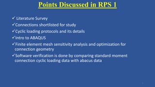
- 1. Points Discussed in RPS 1 Literature Survey Connections shortlisted for study Cyclic loading protocols and its details Intro to ABAQUS Finite element mesh sensitivity analysis and optimization for connection geometry Software verification is done by comparing standard moment connection cyclic loading data with abacus data 1
- 2. Conclusive points of RPS 1 Pre Qualified welded connections can be used for further study Sufficient research literature is available Mesh sensitivity analysis shows that 20mm element size is sufficient SAC protocol loading can be used to study the cyclic behavior of steel connections Nonlinear hysteretic behavior of steel connection achieved in ABAQUS is well matched with tested data of the connection. 2
- 3. Points Discussed in RPS 2 Stress concentration problem identified in steel connections and literature reviewed Pre-qualified connections designed as per AISC and IS code guidelines FEM modeling done in ABAQUS Load vs Displacement behavior Maximum von mises stress vs load behavior Stress concentration factor vs load behavior 3
- 4. Conclusive points of RPS 2 Parallel sections can satisfy all the design requirement SCF factor in haunch connection is lowest Stiffness of haunch connection is highest High plastic strain in web region of column so diagonal stiffener of doubler plate is required SCF factor stay linear in elastic stage and decreases as in the plastic stage Reinforcements in connections like column web stiffener plats and brackets reduces SCF 4
- 6. RPS 3 Points A) Parametric study of type 1 connection for SCF Sectional properties as per IS code Applied loading as per beam design Connection matrix Connection design check for reinforcements Considered non dimensional factors for parametric study ABAQUS modeling and results Linear regression equation development and check Conclusions 6
- 7. RPS 3 Points B) Parametric study of type 1 connection for SCF Specimens for cyclic behavior Applied SAC loading protocol Nonlinear cyclic behavior analysis results of ABAQUS Conclusions 7
- 8. SCF factor • When an engineering component is being subjected to fluctuation loads, its life is adversely affected because premature failure takes place through the surface • Fatigue is a phenomenon featured by the decay of the member’s strength progressively leads to the appearance of cracks and eventually sudden and catastrophic failure of the member • Many factors control fatigue life of welded joints. Joint type, joint loading and detailing of the joint are among the most critical factors that must be considered. The type of the loading depends mainly on the type of the structure. • The localized peak stresses are defined as the nominal stresses multiplied by stress concentration factor (SCF). 8
- 9. • Hot spot stresses are usually defined as the maximum or peak geometric stresses that occur where cracks would initially be nucleated 9
- 10. 1.5 Nominal stresses • The nominal stresses are the maximum stresses that develop in the member when being subjected to forces. • Theses stresses are based on the elastic behavior of the member and derived from the basic beam theory. Due to weld components, stress raisers are not considered in normal stress calculation, Determining the nominal stresses is a straightforward task. 10
- 11. Type of connections Type 1 Type 2 Type 3 Type 4 11
- 12. Study of building under EQ loading and member selections For the selection of section for the research study the real geometrical building with real earthquake loading has been selected and has been designed according to IS 800 : 2007 Building is designed in STAAD Pro. The bottom part of building at plinth and below plinth is of RCC Clear height of building is 4m One direction the moment frame and in another direction the braced frame with shear connections has been designed. 12
- 14. Loading consideration • Earthquake loading has been considered as per IS 1893 : 2016 part 1. • The building is considered in zone 3 type with damping of 2%. • Z = 0.16, R = 4 as per IS 1893:2005 part 4, I = 1 • Dead load of 150mm thick slab and outer peripheral brick wall load has been considered. • Live load of 4 kN / m2 considered for medium industrial usages as per IS 872 part 2 14
- 15. Load combinations for plastic steel design of steel structures as per IS 1893 part 4 cl. 7.3.1 • 1.7 DL + 1.7 LL • 1.7 DL + 1.7 EQX • 1.7 DL – 1.7 EQX • 1.7 DL + 1.7 EQZ • 1.7 DL – 1.7 EQZ • 1.3 DL + 1.3 LL + 1.3 EQX • 1.3 DL + 1.3 LL – 1.3 EQX • 1.3 DL + 1.3 LL + 1.3 EQZ • 1.3 DL + 1.3 LL – 1.3 EQZ 15
- 16. Sectional properties • All main beams were assigned with IPE300 / NPB300 as per IS 22778:2004 code for parallel beam sections. • All secondary beams were assigned with NPB 140 • All columns are provided with HE200A • Fy = 250 Mpa with Fu = 420 Mpa material properties has been considered in the design 16
- 17. STAAD model of building 17
- 18. Design output and Unity check • Load case 1.3 DL + 1.3 LL – 1.3 EQX is governing in the design. • So max end moment and shear for which the connection should be designed is as follows • Mu = 80 kN.m and Vu = 84.01 kN 18
- 19. Connection design • Type 1 & Type 2 Connection design • For bending A = 2 * 150 mm (width of beam flange) = 300 mm2 • Ixx = 2 x 150 x (150)^2 = 6.75 x 10^6 mm4 • Z = Ixx / Y = (6.75 x 10^6) / 150 = 45 x 10^3 • Normal stress = 4 kN / 300 mm = 0.013 kN / mm • Bending stress = (80 x 10^3) / (45 x 10^3) = 1.77 kN / m • Vector sum of both stresses = 1.77 kN / m • Weld Size = (1.77 x 10^3) / (510 x (1.73 x 1.25)) = 7.514 < 10.7 (flange thickness of IPE300 beam) • So full flange will be grove weld with may welding access hole may be provided. 19
- 20. • For Shear • Dimension available = 300 – 10.7 x 2 -15 = 263.6 let’s 200 mm • Weld size = 84 x 10^3 / (0.7 x 2 x 260 x (510 / (1.73 x 1.25)) = 0.979 mm • So minimum 5mm filet weld size is adopted. • Column check for stiffeners Check =0.4 √ (Af / 1.1) = 0.4 x √ ( 150 x 10.7) / 1.1 = 15.27 > 10 mm = tfc • Hence the column stiffeners is required for sufficient rigidity • K = tfc + twc = 10 + 6.5 = 16.5 • Local web yielding • Pbf = Fwc x twc x (5K + tfb) / 1.1 = 250 x 10 x (5 x 16.5 + 10.7) / 1.1 = 211.81 kN 20
- 21. • Kaufmann, E.J., Fisher, J.W., DiJulio, R.M., and Gross, J.L. (1997). "Failure Analysis of Welded Steel Moment Frames Damaged in the Northridge Earthquake," NIS-TIR 5944, National Institute of Standards and Technol-ogy, Gaithersburg, MD. • Kaufmann, E.J., Xue, M., Lu, L.W., and Fisher, J.W (1996) "Achieving ductile behavior of moment connections," Modern Steel Construction, American Institute of Steel Construction, Inc., January 1996. • Tong, L. W., Zheng, H. Z., Mashiri, F. R. & Zhao, X. L., 2013. Stress concentration factors in circularhollow section and square hollow section T-connections: Experiments, Finite-Element Analysis,and Formulas'. Journal of Structural Engineering, 139(11), pp. 1866-1881. • UEG, 1987. Review of current methods for determining hot-spot stresses and stress concentrationfactors, London, UK: UEG's Tubular Joint Group. • Ummenhofer, T. et al., 2011. Extension of the fatigue life of existing and new welded hollow section joints, Germany: CIDECT. • Van Delft, D. R., Noordhoek, C. & Da Re, M. L., 1987. The results of the European fatigue tests on welded tubular joints compared with SCF formulas and design lines. Steel in Marine Structures, Elsevier Applied Science Publishers, Ltd., pp. 565-577. • Van Delft, D. V., Noordhoek, C. & de Back, J., 1985. Evaluation of the European fatigue test data on large sized weld tubular joints for offshore structures. Houston, USA, Offshore Technology Conference. • Van Wingerde, A. M., 1992. The fatigue behavior of T- and X-joint made of square hollow sections, The Netherland: Heron. • Van Wingerde, A. M., Packer, J. A. & Wardenier, J., 1997. IIW fatigue rules for tubular joints. San Francisco, IIW International Conference on performance of Dynamically Loaded Structures. • Winkel, G. D., 1998. The static strength of I-beam to circular hollow section column connections, The Netherlands: Delft University of Technology. • Yeoh, S. K., Soh, A. K. & Soh, C. K., 1994. Behaviour of tuular T-joint subjected to combined loadings. Journal of Construct. Steel. • Zhao, X.-L.et al., 2001. Design guide for circular and rectangular hollow section welded joints under fatigue loading. s.l.:CIDECT. 21
- 22. 22