SlideShare a Scribd company logo
1 of 59
Download to read offline
ENGINE - 1NZ-FE ENGINE
00REG01Y
00REG02Y
EG-2
1NZ-FE ENGINE
JDESCRIPTION
The 1NZ-FE engine is a in-line, 4-cylinder, 1.5 liter, 16-valve DOHC engine.
The VVT-i (Variable Valve Timing-intelligent) system, DIS (Direct Ignition System) and ETCS-i (Electronic
Throttle Control System-intelligent) are used on this engine in order to realize high performance, quietness,
fuel economy and clean emission.
ENGINE - 1NZ-FE ENGINE
247EG02
: IN Opening Angle
: EX Opening Angle
VVT-i Operation Angle TDC
2_
7_
33_
52_
VVT-i Operation Angle 12_
42_
BDC
EG-3
" Engine Specifications A
No. of Cyls. & Arrangement 4-Cylinder, In-line
Valve Mechanism 16-Valve DOHC, Chain Drive (with VVT-i)
Combustion Chamber Pentroof Type
Manifolds Cross-Flow
Fuel System SFI
Ignition System DIS
Displacement cm3 (cu. in.) 1497 (91.3)
Bore x Stroke mm (in.) 75.0 x 84.7 (2.95 x 3.33)
Compression Ratio 10.5 : 1
Max. Output*1 (SAE-NET) 79 kW @ 6000 rpm (106 HP @ 6000 rpm)
Max. Torque*1 (SAE-NET) 139 N.m @ 4200 rpm (103 ft lbf @ 4200 rpm)
Intake
Open -7 _ - 33_ BTDC
Valve
Intake
Close 52_ - 12_ ABDCValve
Timing
Exhaust
Open 42_ BBDCg
Exhaust
Close 2_ ATDC
Firing Order 1 - 3 - 4 - 2
Research Octane Number 90 or higher
Octane Rating 87 or higher
Oil Grade ILSAC
Tailpipe Emission Regulation TIRE2, ULEV-II
Evaporative Emission Regulation ORVR
Engine Service Mass*2
kg (lb)
M/T 83.2 (183.4)Engine Service Mass
(Reference)
kg (lb)
A/T 77.8 (171.5)
*1: Maximum output and torque rating is determined by revised SAE J1349 standard.
*2: Weight shows the figure with the oil fully filled.
" Valve Timing A
ENGINE - 1NZ-FE ENGINEEG-4
JFEATURES OF 1NZ-FE ENGINE
The 1NZ-FE engine has been able to achieve the following performance through the adoption of the items
listed below.
(1) High performance and fuel economy
(2) Low noise and vibration
(3) Lightweight and compact design
(4) Good serviceability
(5) Clean emission
Section Item (1) (2) (3) (4) (5)
A cylinder block made of aluminum is used. f
Engine Proper
An offset crankshaft is used. f f f
Engine Proper
The taper squish shape is used for the combustion
chamber.
f f
Valve A timing chain and chain tensioner are used. f f fValve
Mechanism The VVT-i system is used. f f
Intake manifold made of plastic is used. f
The linkless-type throttle body is used. f f
Intake and A stainless steel exhaust manifold is used. f
Exhaust System Two TWCs (Three Way Catalytic Converter) are used. f
A rearward exhaust layout is used to realize the early
activation of the catalyst.
f
12-hole type injector is used. f f
Fuel System
The fuel returnless system is used. f f f
Fuel System
Quick connectors are used to connect the fuel hose with
the fuel pipes.
f
The long-reach type spark plugs are used. f
Ignition System The DIS (Direct Ignition system) makes ignition timing
adjustment unnecessary.
f f f
The ETCS-i (Electronic Throttle Control
System-intelligent) is used.
f f
Engine Control
The non-contact sensor is used in the throttle position
sensor and accelerator pedal position sensor.
f
Engine Control
System The cranking hold function is used. fy
Evaporative emission control system is used. f
The use of an air fuel ratio sensor allows for precise
control.
f
ENGINE - 1NZ-FE ENGINE
247EG03
EX
Injector
IN
Water Jacket
Taper Squish
193EG05247EG04
Bore Center
Crankshaft Center
Crankshaft
Center
Maximum
Pressure
Offset Crankshaft Center Crankshaft
EG-5
JENGINE PROPER
1. Cylinder Head
D The injectors are installed in the cylinder head to reduce the distance from injector to intake valve, thus
it prevents the fuel from adhering to the intake port walls, and reduce exhaust emissions.
D The routing of the water jacket in the cylinder head is optimized to achieve high cooling performance.
D Through the use of the taper squish combustion chamber, the engine’s knocking resistance and fuel
efficiency have been improved.
2. Cylinder Block
D Lightweight aluminum alloy is used for the cylinder block.
D Through the use of the offset crankshaft, the bore center is shifted 12 mm (0.472 in.) towards the intake,
in relation to the crankshaft center. Thus, the side force to cylinder wall is reduced when the maximum
pressure is applied, which contributes to fuel economy.
ENGINE - 1NZ-FE ENGINE
00REG19Y
A
A
Irregularly shaped outer
casting surface of liner Cylinder Block
Liner
A - A Cross Section
247EG06
Taper Squish Shape
Piston Ring
EG-6
D The liners are the spiny-type, which have been manufactured so that their casting exterior forms a large
irregular surface in order to enhance the adhesion between the liners and the aluminum cylinder block.
The enhanced adhesion helps improve heat dissipation, resulting in a lower overall temperature and heat
deformation of the cylinder bores.
3. Piston
D The piston is made of aluminum alloy
D The piston head portion is used a taper squish shape to accomplish fuel combustion efficiency.
D Semi floating type piston pins are used.
D By increasing the machining precision of the cylinder bore diameter, only one size of piston is available.
ENGINE - 1NZ-FE ENGINE
171EG07
Plastic Region Tightening Bolts
171EG08
Crankshaft Position
Sensor Rotor
Oil Hole
Crank Pin
No.5 Journal
Balance Weight
No.4 Journal
No.3 JournalNo.2 Journal
No.1 Journal
EG-7
4. Connecting Rod
D The connecting rods and caps are made of high
strength steel for weight reduction.
D Nutless-type plastic region tightening bolts are
used for a light design.
5. Crankshaft
D The diameter and width of the pins and journals have been reduced, and the pins for the No.1 and No.4
cylinders have been made highly rigid to realize a lightweight and low-friction performance.
D The crankshaft has 5 journals and 4 balance weights.
D A crankshaft position sensor rotor is pressed into the crankshaft to realize an integrated configuration.
ENGINE - 1NZ-FE ENGINE
165EG12171EG09
Chain
Tension Arm
Chain
Tensioner
VVT-i
Controller
Timing Chain Exhaust Camshaft
Intake
Camshaft
Chain Guide
Camshaft
Valve Lifter
Valve
Service Tip
The adjustment of the valve clearance is accomplished by selecting and replacing the appropriate
valve lifters. Adjusting valve lifters are available in 35 increments of 0.020 mm (0.0008 in.), from
5.060 mm (0.1992 in.), to 5.740 mm (0.2260 in.).
For details, refer to 2006 Yaris Repair Manual (Pub. No. RM00R0U).
EG-8
JVALVE MECHANISM
1. General
D The shimless type valve lifter is used to increase the amount of the valve lift.
D The intake and exhaust camshafts are driven by a timing chain.
D The VVT-i system is used to realize fuel economy, engine performance and reduce exhaust emissions. For
details of VVT-i control, see page EG-41.
ENGINE - 1NZ-FE ENGINE
247EG08
VVT-i Controller
Exhaust Camshaft
Timing Rotor
Intake Camshaft
Oil Passage (Advance)
Oil Passage (Retard)
247EG09
Spring
Plunger
Cam
Cam Spring
Check Ball
Chain
Slipper
Timing Chain
Chain Damper
Oil Jet
EG-9
2. Camshaft
D Oil passages are provided in the intake camshaft in order to supply engine oil to the VVT-i system.
D A VVT-i controller is provided on the front of the intake camshaft to vary the timing of the intake valves.
D A Timing rotor is provided behind the intake camshaft to trigger the camshaft position sensor.
3. Timing Chain and Chain Tensioner
D A roller type timing chain with an 8.0 mm (0.315 in.) pitch is used to make the engine compact and reduce
noise.
D The timing chain is lubricated by an oil jet.
D The chain tensioner uses a spring and oil pressure to maintain proper chain tensioner at all times. The chain
tensioner suppresses noise generated by the timing chain.
D A ratchet type non-return mechanism is used in the chain tensioner.
" Chain Tensioner A
ENGINE - 1NZ-FE ENGINE
171EG32171EG31
Service Hole for
Chain Tensioner
Front View
Oil Pump
Back View
EG-10
4. Timing Chain Cover
D A single-piece, aluminum diecast timing chain cover that entirely seals the front portion of the cylinder
block and cylinder head is used.
D A service hole for the chain tensioner is provided in the timing chain cover to improve serviceability.
ENGINE - 1NZ-FE ENGINE
171EG14
Camshaft Timing
Oil Control Valve
VVT-i
Controller
Chain
Tensioner
Oil Pump Oil Strainer
Oil Filter
171EG15
Main Oil Hole
Crankshaft
Journal
Oil Filter
Relief
Valve
Connecting
Rod
Oil Pump
Oil Jet
Oil Strainer
Piston
Oil Jet
Cylinder Head
Camshaft Timing
Oil Control Valve
Filter
Chain
Tensioner
Timing Chain
Intake
Camshaft
Journal
Exhaust
Camshaft
Journal
Camshaft Timing
Oil Control Valve
VVT-i
Oil Pan
EG-11
JLUBRICATION SYSTEM
1. General
D The lubrication circuit is fully pressurized and oil passes through an oil filter.
D A trochoid gear type oil pump, which is driven directly by the crankshaft, is provided in the front of the
cylinder block.
D The oil filter is installed diagonally downward from the side of the cylinder block to realize excellent
serviceability.
D The intake camshaft is provided with a VVT-i controller, and cylinder head is provided with a camshaft
timing oil control valve. This system is operated by the engine oil.
" Oil Capacity A Liter (US qts, Imp qts)
Dry 4.1 (4.3, 3.6)
with Oil Filter 3.7 (3.9, 3.3)
without Oil Filter 3.4 (3.6, 3.0)
" Oil Circuit A
ENGINE - 1NZ-FE ENGINE
00REG16Y
Water Pump
From Radiator
To Radiator
From Heater Core
To Heater Core
To Throttle Body
193EG08
Bypass
Passage
Water Pump
Thermostat
Cylinder Head
Cylinder Block
Radiator
Throttle
Body
Heater Core
EG-12
JCOOLING SYSTEM
D The cooling system is a pressurized, forced-circulation type.
D A thermostat with a bypass valve is located on the water inlet housing to maintain suitable temperature
distribution in the cooling system.
D An aluminum radiator core is used for weight reduction.
D The flow of the engine coolant makes a U-turn in the cylinder block to ensure a smooth flow of the engine
coolant.
D A single cooling fan provides both the cooling and air conditioner performance.
D The TOYOTA genuine Super Long Life Coolant (SLLC) is used.
" System Diagram A
ENGINE - 1NZ-FE ENGINE EG-13
" Engine Coolant Specifications A
Engine
Coolant
Type
TOYOTA genuine Super Long Life
Coolant (SLLC) or similar high quality
ethylene glycol based non-silicate,
non-amine, non-nitrite and non-borate
coolant with long-life hybrid organic acid
technology (coolant with long-life hybrid
organic acid technology is a combination
of low phosphates and organic acids.) Do
not use plain water alone.
Color Pink
Capacity M/T 4.8 (5.1, 4.2)Capacity
Liters (US qts, Imp. qts) A/T 4.7 (5.0, 4.1)
Maintenance Intervals
First Time 100,000 miles (160,000 km)
Maintenance Intervals
Subsequent Every 50,000 miles (80,000 km)
Thermostat Opening Temperature _C (_F) 80 - 84 (176 - 183)
D SLLC is pre-mixed (the U.S.A. models: 50 % coolant and 50 % deionized water, the Canada. models:
55 % coolant and 45 % deionized water). Therefore, no dilution is needed when SLLC in the vehicle is
added or replaced.
D If LLC is mixed with SLLC, the interval for LLC (ever 40,000 km/24,000 miles or 24 months) should
be used.
ENGINE - 1NZ-FE ENGINE
00REG06Y
Exhaust Manifold
Intake Manifold
Air Cleaner
TWCs
Sub Muffler
Main
Muffler
EG-14
JINTAKE AND EXHAUST SYSTEM
1. General
D A plastic intake manifold is used for weight reduction.
D The linkless-type throttle body is used to realize excellent throttle control.
D ETCS-i (Electronic Throttle Control System-intelligent) provides excellent throttle control. For details,
see page EG-36.
D The exhaust pipe uses a ball joint in order to achieve a simple construction and reliability.
ENGINE - 1NZ-FE ENGINE
00REG03Y
Charcoal Filter
Air Cleaner Cap
Air Cleaner Element
(Nonwovens Fabric)
Service Tip
The charcoal filter, which is maintenance-free, cannot be removed from the air cleaner cap.
00REG04Y
DC Motor
Throttle Valve
Reduction Gears
Throttle Position Sensor
EG-15
2. Air Cleaner
D A nonwoven, full-fabric type air cleaner element is used.
D A charcoal filter, which adsorbs the HC that accumulates in the intake system when the engine is stopped,
is used in the air cleaner cap in order to reduce evaporative emissions.
3. Throttle Body
D The linkless-type throttle body is used and it realizes excellent throttle control.
D A DC motor with excellent response and minimal power consumption is used for the throttle control motor.
The ECM performs the duty ratio control of the direction and the amperage of the current that flows to
the throttle control motor in order to regulate the opening angle of the throttle valve.
ENGINE - 1NZ-FE ENGINE
00REG07Y
Mesh Type Gasket
00REG08Y
Ball Joint
Gasket
Ball Joint
TWCs
Front Pipe
Main Muffler
Tail Pipe
Ball Joint
Sub Muffler
EG-16
4. Intake Manifold
D The intake manifold has been made of plastic to
reduce the weight and the amount of heat
transferred from the cylinder head. As a result,
it has become possible to reduce the intake
temperature and improve the intake volumetric
efficiency.
D A mesh type gasket is used in order to reduce
the intake noise.
5. Exhaust Pipe and Muffler
A ball joint is used to joint the exhaust manifold to the exhaust front pipe, and the exhaust front pipe to the
exhaust tail pipe. As a result, a simple construction and improved reliability have been realized.
ENGINE - 1NZ-FE ENGINE
00REG12Y
Fuel Pump
D Fuel filter
D Pressure Regulator
D Fuel Sender Gauge
D Fuel Cutoff Valve
Canister
Fuel Tank
Quick Connector
Injector
View from Bottom
EG-17
JFUEL SYSTEM
1. General
D The fuel returnless system is used to reduce evaporative emissions.
D A fuel tank made of multi-layer plastic is used.
D A fuel cut control is used to stop the fuel pump when the SRS airbag is deployed in a front or side collision.
For details, see page EG-45.
D A quick connector is used to connect the fuel pipe with the fuel hose to realize excellent serviceability.
D A compact 12-hole type injector is used to ensure the atomization of fuel.
D The ORVR (On-Board Refueling Vapor Recovery) system is used. For details, see page EG-46.
ENGINE - 1NZ-FE ENGINE
179EG11
To Canister
Fuel Cutoff Valve
Fuel Filter
Fuel Pump
Injector
Pulsation
Damper Delivery Pipe
Pressure Regulator
Fuel Tank
Module
Fuel Pump
Assembly
00REG13Y
Fuel Tank Outside
Fuel Tank Inside
HDPE (High Density Polyethylene)
Regrind Material
Adhesive
EVOH (Ethylene Vinyl Alcohol Copolymer)
Adhesive
HDPE (High Density Polyethylene)
EG-18
2. Fuel Returnless System
This system is used to reduce the evaporative emission. As shown below, integrating the fuel filter, pressure
regulator, fuel sender gauge, and fuel cutoff valve with module fuel pump assembly enables to discontinue
the return of fuel from the engine area and prevent temperature rise inside the fuel tank.
3. Fuel Tank
Low permeability has been realized through the use of the multi-layered plastic fuel tank. This fuel tank
consists of six layers using four types of materials.
ENGINE - 1NZ-FE ENGINE
165EG25
Camshaft
Position
Sensor
Crankshaft
Position
Sensor
Various
Sensor
ECM
IGT1
IGT2
IGT3
IGT4
IGF
+B
Ignition Coil
(with Igniter)
No.1
Cylinder
No.2
Cylinder
No.3
Cylinder
No.4
Cylinder
171EG27
Igniter
Iron Core
Plug Cap
Primary Coil
Secondary Coil
EG-19
JIGNITION SYSTEM
1. General
D A DIS (Direct Ignition System) is used. The DIS in this engine is an independent ignition system, which
has one ignition coil for each cylinder. The DIS ensures the ignition timing accuracy, reduces high-voltage
loss, and realizes the overall reliability of the ignition system by eliminating the distributor.
D The spark plug caps, which connect to the spark plugs, are integrated with the ignition coils. Also, the
igniters are enclosed to simplify the system.
D Long-reach type iridium-tipped spark plugs are used.
" Ignition Coil with Igniter A
ENGINE - 1NZ-FE ENGINE
281EG73
Long-Reach Type Conventional Type
Iridium Tip
EG-20
2. Spark Plug
D Long-reach type iridium-tipped spark plugs are used.
D Long-reach type of spark plugs allows the area of the cylinder head to receive the spark plugs to be made
thick. Thus, the water jacket can be extended near the combustion chamber, which contributes to cooling
performance.
D Iridium-tipped spark plugs are used to realize a 100,000 km (62,500 mile) maintenance-free operation.
By making the center electrode of iridium, the same ignition performance as the platinum-tipped type
spark plug and excellent of durability have been realized.
" Specification A
DENSO SK16R11
NGK IFR5A-11
Plug Gap mm (in.) 1.1 (0.043)
ENGINE - 1NZ-FE ENGINE
206EG41206EG40
Stator Segment
Conductor
Stator Segment
Conductor
Joined
A
A
Joined Segment
Conductor System
A - A Cross
Section
Segment Conductor
Type Generator
Stator Stator Conductor Wire
Conductor Wire
B
B Wiring System
B - B Cross
Section
Conventional Type Generator
Stator
Segment
Conductor
Cross Section
206EG42
Stator of Segment Conductor
Type Generator
EG-21
JCHARGING SYSTEM
D A compact and lightweight segment conductor type generator that generates high amperage output in a
highly efficient manner is used as standard equipment.
D This generator has a joined segment conductor system, in which multiple segment conductors are welded
together to form the stator. Compared to the conventional wiring system, the electrical resistance is
reduced due to the shape of the segment conductors, and their arrangement helps to make the generator
compact.
" Specifications A
Type SE08
Rated Voltage 12 V
Rated Output 80 A
Initial Output Starting Speed 1,250 rpm Max.
ENGINE - 1NZ-FE ENGINE
00REG20Y
Generator
E
Regulator
B
M
IG
S
L
Ignition Switch
Discharge
Warning Light
EG-22
" Wiring Diagram A
ENGINE - 1NZ-FE ENGINE
271EG38
PS Type
(PS1.6)
P Type
(P0.8)
Armature
Surface Commutator
Permanent Magnet
Brush
Length
EG-23
JSTARTING SYSTEM
1. General
D A P (conventional planetary reduction) type starter is used in the models for U.S.A.
D A PS (planetary reduction-segment conductor motor) type starter is used in the models for Canada and
cold areas of the U.S.A.
" Specification A
Destination U.S.A.
Canada,
Cold Areas of U.S.A.
Starter Type P Type PS Type
Rating Output 0.8 kW 1.6 kW
Rating Voltage 12 V z
Length*1 mm (in.) 154 (6.1) 133 (5.2)
Weight g (lb) 2800 (6.2) z
Rotation Direction*2 Clockwise z
*1: Length from the mounted area to the rear end of the starter
*2: Viewed from Pinion Side
ENGINE - 1NZ-FE ENGINE
206EG20
Conventional Type
Armature
Armature
B
B
A
A
PS Type
Brush
Commutator
Brush
Surface Commutator
Square-Shaped
Conductor
Round-Shaped
Conductor
A - A Cross Section
(PS Type)
B - B Cross Section
(P Type)
222EG15
Main Magnet
Yoke
Interpolar Magnet
Main Magnet
Armature
Cross Section of Yoke
Magnetic Flux Generated by
Interpolar Magnets
N
S
N
N
S
S
Magnetic Flux Generated by
Relationship Between Main Magnets
EG-24
2. PS (Planetary reduction-Segment conductor motor) Type Starter
Construction
D Instead of constructing the armature coil with P type of round-shaped conductor wires, the PS type starter
uses square conductors. With this type of construction, the same conditions that are realized by winding
numerous round-shaped conductor wires can be achieved without increasing the mass. As a result, the
output torque has been increased, and the armature coil has been made compact.
D Because the surface of the square-shaped conductors that are used in the armature coil functions as a
commutator, the overall length of the PS type starter has been shortened.
D Instead of the field coils used in the P type starter, the PS type starter uses two types of permanent
magnets: the main magnets and the interpolar magnets. The main and interpolar magnets are arranged
alternately inside the yoke, allowing the magnetic flux that is generated between the main and interpolar
magnets to be added to the magnetic flux that is generated by the main magnets. In addition to increasing
the amount of magnetic flux, this construction shortens the overall length of the yoke.
ENGINE - 1NZ-FE ENGINE EG-25
JENGINE CONTROL SYSTEM
1. General
The engine control system for the 1NZ-FE engine has the following systems.
System Outline
’06
Model
’05
Model
SFI
Electronic Fuel
Injection
An L-type EFI system detects the intake air mass with a
hot-wire type air flow meter.
f f
ESA
Electronic Spark
Advance
Ignition timing is determined by the ECM based on signals
from various sensors. The ECM corrects ignition timing in
response to engine knocking.
f f
ETCS-i
Electronic
Optimally controls the throttle valve opening in accordance
with the amount of accelerator pedal effort and the condition
of the engine and vehicle.
f -
Electronic
Throttle Control
System-intelligent
See page EG-36
D A linkless-type is used without an accelerator.
D An accelerator pedal position sensor is provided on the
accelerator pedal.
D A non-contact type throttle position sensor and accelerator
pedal position sensor are used.
f -
VVT-i
Variable Valve
Timing-intelligent
See page EG-41
Controls the intake camshaft to optimal valve timing in
accordance with the engine condition.
f f
Fuel Pump Control
See page EG-45
D Fuel pump operation is controlled by signals from the ECM.
D The operation of the fuel pump will stop when the airbag
is deployed.
f f
Air Fuel Ratio Sensor
and Oxygen Sensor
Heater Control
Maintains the temperature of the air fuel ratio sensor or
oxygen sensor at an appropriate level to realize accuracy of
detection of the oxygen concentration in the exhaust gas.
f -
Oxygen Sensor
Heater Control
Maintains the temperature of the oxygen sensor at an
appropriate level to realize accuracy of detection of the
oxygen concentration in the exhaust gas.
- f
The ECM controls the purge flow of evaporative emissions
(HC) in the canister in accordance with engine conditions.
f f
Evaporative
Emission
Using 3 VSVs and a vapor pressure sensor, the ECM detects any
evaporative emission leakage occurring between the fuel tank
and charcoal canister through changes in the fuel tank pressure.
- f
Control
See page EG-46
Approximately five hours after the ignition switch has been
turned OFF, the ECM operates the canister pump module to
detect any evaporative emission leakage occurring in the
evaporative emission control system through changes in the
reference orifice pressure.
f -
Air Conditioner
Cut-off Control*1
By turning the air conditioner compressor OFF in accordance
with the engine condition, drivadility is maintained.
f f
Cooling Fan Control
See page EG-56
Cooling fan operation is controlled by signals from ECM based
on the engine coolant temperature sensor signal (THW).
f f
*1: for Models with Air Conditioning System
ENGINE - 1NZ-FE ENGINEEG-26
System Outline
’06
Model
’05
Model
Starter Control
Cranking Hold
Function
See Page EG-57
Once the ignition switch is turned to the START position,
this control continues to operate the starter until the engine
is started.
f -
Engine Immobilizer*2 Prohibits fuel delivery and ignition if an attempt is made to
start the engine with an invalid ignition key.
f f
Diagnosis
See Page EG-59
When the ECM detects a malfunction, the ECM diagnoses
and memorizes the failed section.
f f
Fail-Safe
See Page EG-59
When the ECM detects a malfunction, the ECM stops or
controls the engine according to the data already in memory.
f f
*2: for Models with Engine Immobilizer System
ENGINE - 1NZ-FE ENGINE
00REG10Y
SENSORS ACTUATORS
MASS AIR FLOW METER
INTAKE AIR TEMPERATURE
SENSOR
CRANKSHAFT POSITION
SENSOR
CAMSHAFT POSITION
SENSOR
THROTTLE POSITION
SENSOR
ENGINE COOLANT
TEMPERATURE SENSOR
ACCELERATOR PEDAL
POSITION SENSOR
KNOCK SENSOR
IGNITION SWITCH
D Ignition Signal
D Start Signal
PARK/NEUTRAL POSITION
SWITCH*1
D Shift Lever Position Signal
COMBNATION METER
D Vehicle Speed Signal
AIR FUEL RATIO SENSOR
(Bank 1, Sensor 1)
HEATED OXYGEN SENSOR
(Bank 1, Sensor 2)
SFI
No.1 INJECTOR
No.2 INJECTOR
No.3 INJECTOR
No.4 INJECTOR
ESA
IGNITION COIL
with IGNITER
SPARK PLUGS
VVT-i
CAMSHAFT TIMING
OIL CONTROL VALVE
ETCS- i
THROTTLE CONTROL
MOTOR
FUEL PUMP CONTROL
CIRCUIT OPENING
RELAY
A/F SENSOR & OXYGEN
SENSOR HEATER CONTROL
A/F SENSOR HEATER
Bank 1, Sensor 1
OXYGEN SENSOR HEATER
Bank 1, Sensor 2
VG
THA
NE
G2
VTA1
VTA2
THW
VPA
VPA2
KNK1
IGSW
STSW,
STA
P,N,D
R,L,2
SPD
A1A+
OX1B
ECM
#10
#20
#30
#40
IGT1
 IGT4
IGF
OC1
M
FC
HT1A
HT1B
EG-27
2. Construction
The configuration of the engine control system in the 1NZ-FE engine is shown in the following chart.
(Continued)
*1: for Automatic Transaxle Models
ENGINE - 1NZ-FE ENGINE
00REG11Y
CANISTER PUMP MODULE
CANISTER PRESSURE SENSOR
TAILLIGHT SWITCH
DEFOGGER SWITCH
STOP LIGHT SWITCH
GENERATOR
SHIFT LOCK ECU
TRANSPONDER KEY ECU*2
DLC3
AIRBAG SENSOR ASSEMBLY
A/C ECU*3
SKID CONTROL ECU*4
BATTERY
EVAPORATIVE EMISSION
CONTROL
CANISTER PUMP MODULE
LEAK DETECTION PUMP
VENT VALVE
PURGE VSV
STATER CONTROL
STARTER RELAY
ACC CUT RELAY
COOLING FAN CONTROL
COOLING FAN RELAY No.1
COOLING FAN RELAY No.2
EFI MAIN RELAY
COMBNATION METER
MIL
PPMP
ELS1
ELS3
STP
ALT
3
IMI
IMO
TC
CANH,
CANL
BATT
MPMP
VPMP
PRG
STAR
ACCR
FAN L
FAN H
MREL
+B
W
ECM
EG-28
*2: for Models with Engine Immobilizer System
*3: for Models with Air Conditioning System
*4: for ABS Models
ENGINE - 1NZ-FE ENGINE
00REG14Y
Accelerator Pedal
Position Sensor
Generator
MIL
DLC3
Park/Neutral
Position Switch*
Ignition
Switch
Circuit Opening Relay ECM
Battery
Throttle
Position
Sensor
Throttle
Control
Motor
Purge VSV
Mass Air Flow Meter
D Intake Air Temperature
Sensor
Camshaft
Position
Sensor
Ignition Coil
with Igniter
Injector
Knock Sensor
Engine
Coolant
Temperature
Sensor
Canister
Filter
Fuel Pump
Crankshaft
Position Sensor
TWCs
Canister Pump Module
D Vent Valve
D Leak Detection Pump
D Canister Pressure Sensor
Heated Oxygen Sensor
(Bank 1, Sensor 2)
Air Fuel Ratio Sensor
(Bank 1, Sensor 1)
EG-29
3. Engine Control System Diagram
*: for Automatic Transaxle Models.
ENGINE - 1NZ-FE ENGINE
00REG15Y
Canister Pump Module
D Vent Valve
D Leak Detection Pump
D Canister Pressure Sensor
Heated Oxygen Sensor
(Bank 1, Sensor 2)
ECM
VSV (for EVAP)
Mass Air Flow Meter
(Built-in Intake Air Temperature Sensor)
Accelerator Pedal
Position Sensor
DLC3
Fuel Pump
Camshaft Timing Oil
Control Valve
Ignition Coil
with Igniter
Camshaft Position
Sensor
Engine Coolant
Temperature
Sensor
Air Fuel Ratio Sensor
(Bank 1, Sensor 1)
Injector
Knock Sensor
Crankshaft Position
Sensor
Throttle Body
EG-30
4. Layout of Main Components
ENGINE - 1NZ-FE ENGINE EG-31
5. Main components of Engine Control System
General
The main components of the 1NZ-FE engine control system are as follows:
Components Outline Quantity Function
ECM 32-bit CPU 1
The ECM optimally controls the SFI, ESA, and IAC
to suit the operating conditions of the engine in
accordance with the signals provided by the sensors.
Air Fuel Ratio
Sensor
(Bank 1, Sensor 1)
Planar Type
with Heater
1
As with the heated oxygen sensor, this sensor detects
the oxygen concentration in the exhaust emission.
However, it detects the oxygen concentration in the
exhaust emission linearly.
Heated Oxygen
Sensor
(Bank 1, Sensor 2)
Cup Type
with Heater
1
This sensor detects the oxygen concentration in the
exhaust emission by measuring the electromotive
force which is generated in the sensor itself.
Mass Air
Flow Meter
Hot-wire Type 1
This sensor has a built-in hot-wire to directly detect
the intake air mass.
Crankshaft
Position Sensor
(Rotor Teeth)
Pickup Coil
Type
(36-2)
1
This sensor detects the engine speed and performs
the cylinder identification.
Camshaft
Position Sensor
(Rotor Teeth)
Pickup Coil
Type
(3)
1 This sensor performs the cylinder identification.
Engine Coolant
Temperature
Sensor
Thermistor
Type
1
This sensor detects the engine coolant temperature
by means of an internal thermistor.
Intake Air
Temperature
Sensor
Thermistor
Type
1
This sensor detects the intake air temperature by
means of an internal thermistor.
Knock Sensor
Non-resonant
Flat Type
1
This sensor detects an occurrence of the engine
knocking indirectly from the vibration of the
cylinder block caused by the occurrence of engine
knocking.
Throttle Position
Sensor
Non-contact
Type
1 This sensor detects the throttle valve opening angle.
Accelerator Pedal
Position Sensor
Non-contact
Type
1
This sensor detects the amount of pedal effort
applied to the accelerator pedal.
Injector 12-Hole Type 4
The injector is an electromagnetically-operated
nozzle which injects fuel in accordance with signals
from the ECM.
ECM
The 32-bit CPU of the ECM is used to realize the high speed for processing the signals.
ENGINE - 1NZ-FE ENGINE
00REG21Y
D13N11
Air Fuel
Ratio
Sensor
A1A+
(3.3V)
A1A-
(2.9V)
ECM
Air Fuel Ratio Sensor Circuit Heated Oxygen Sensor Circuit
Heated
Oxygen
Sensor
OX1B
EX1B
ECM
4.2
2.2
1
0.1
Air Fuel Ratio
Sensor Output (V)*
Heated Oxygen
Sensor Output (V)
11 (Rich) 14.7
Air Fuel Ratio
19 (Lean)
: Air Fuel Ratio Sensor
: Heated Oxygen Sensor
EG-32
Air Fuel Ratio Sensor and Heated Oxygen Sensor
1) General
D The air fuel ratio sensor and heated oxygen sensor differ in output characteristics.
D Approximately 0.4V is constantly applied to the air fuel ratio sensor, which outputs an amperage that
varies in accordance with the oxygen concentration in the exhaust emission. The ECM converts the
changes in the output amperage into voltage in order to linearly detect the present air-fuel ratio.
D The output voltage of the heated oxygen sensor changes in accordance with the oxygen concentration
in the exhaust emission. The ECM uses this output voltage to determine whether the present air-fuel
ratio is richer or leaner than the stoichiometric air-fuel ratio.
*: This calculation value is used internally in the ECM, and is not an ECM terminal voltage.
ENGINE - 1NZ-FE ENGINE
271EG45
Alumina
Dilation Layer
Alumina
Atmosphere
Platinum
Electrode
Heater
Sensor Element (Zirconia)
Heater
Platinum
Electrode
Atmosphere
Sensor Element
(Zirconia)
Planer Type Air Fuel Ratio Sensor Cup Type Heated Oxygen Sensor
204EG54
Temperature Sensing
Element
Platinum Hot-wire
Element
Air Flow Intake Air
Temperature Sensor
EG-33
2) Construction
D The basic construction of the air fuel ratio sensor and heated oxygen sensor is the same. However, they
are divided into the cup type and the planar type, according to the different types of heater construction
that are used.
D The cup type sensor contains a sensor element that surrounds a heater.
D The planer type sensor uses alumina, which excels in heat conductivity and insulation, to integrate a
sensor element with a heater, thus realizing the excellent warm-up performance of the sensor.
 Warm-up Specification A
Sensor Type Planer Cup Type
Warm-up Time Approx. 10 sec. Approx. 30 sec.
Mass Air Flow Meter
D The compact and lightweight mass air flow meter, which is a plug-in type, allows a portion of the intake
air to flow through the detection area. By directly measuring the mass and the flow rate of the intake air,
the detection precision is ensured and the intake air resistance is reduced.
D This mass air flow meter has a built-in intake air temperature sensor.
ENGINE - 1NZ-FE ENGINE
00REG09Y
230LX12 238EG79
Throttle Body
Throttle Position
Sensor Portion
Magnetic
Yoke
Hall IC
Cross Section
Throttle Position
Sensor
Magnetic Yoke
Hall
IC
Hall
IC
VTA1
E
VC
VTA2
ECM
Output
Voltage
V
0
5
Throttle
Valve
Fully Close
Throttle
Valve
Fully Open
90_
Throttle Valve Opening Angle
VTA2
VTA1
Service Tip
The inspection method differs from the conventional contact type throttle position sensor because
this non-contact type sensor uses a Hall IC.
For details, refer to the 2006 Yaris Repair Manual (Pub. No. RM00R0U).
EG-34
Throttle Position Sensor
The throttle position sensor is mounted on the throttle body to detect the opening angle of the throttle valve.
The throttle position sensor converts the magnetic flux density that changes when the magnetic yoke
(located on the same axis as the throttle shaft) rotates around the Hall IC into electric signals to operate the
throttle control motor.
ENGINE - 1NZ-FE ENGINE
00SEG39Y
228TU25228TU24
A
A
Internal Construction
Accelerator
Pedal Arm
Magnetic Yoke
Hall IC
A - A Cross Section
Accelerator Pedal
Position Sensor
Magnetic Yoke
Hall
IC
Hall
IC
VPA
EPA
VCPA
VPA2
EPA2
VCP2
ECM
V
5
0
Output
Voltage
Fully
Close
Fully
Open
Accelerator Pedal Depressed Angle
VPA2
VPA
90_
Service Tip
The inspection method differs from the conventional contact type accelerator pedal position sensor
because this non-contact type sensor uses a Hall IC.
For details, refer to the 2006 Yaris Repair Manual (Pub. No. RM00R0U).
EG-35
Accelerator Pedal Position Sensor
The non-contact type accelerator pedal position sensor used a Hall IC.
D The magnetic yoke that is mounted at the accelerator pedal arm rotates around the Hall IC in accordance with
the amount of effort that is applied to the accelerator pedal. The Hall IC converts the changes in the magnetic
flux that occur at that time into electrical signals, and outputs them as of accelerator pedal effort to the ECM.
D The Hall IC contains circuits for the main and sub signals. It converts the accelerator pedal depressing
angles into electric signals with two differing characteristics and outputs them to the ECM.
ENGINE - 1NZ-FE ENGINE
00REG17Y
Accelerator Pedal
Position Sensor
Throttle Valve
Throttle Position Sensor
Throttle
Control
Motor
Mass Air
Flow Meter ECM
Skid
Control
ECU*
Ignition
Coil
Fuel
Injector
: CAN
EG-36
6. ETCS-i (Electronic Throttle Control System-i)
General
D The ETCS-i is used, providing excellent throttle control in all the operating ranges.
D The accelerator cable has been discontinued, and an accelerator pedal position sensor has been provided
on the accelerator pedal.
D In the conventional throttle body, the throttle valve opening is determined invariably by the amount of
the accelerator pedal effort. In contrast, the ETCS-i uses the ECM to calculate the optimal throttle valve
opening that is appropriate for the respective driving condition and uses a throttle control motor to control
the opening.
D The ETCS-i controls the IAC (Idle Air Control) system and cruise control system.
D In case of an abnormal condition, this system switches to the limp mode.
 System Diagram A
*: for ABS Models
ENGINE - 1NZ-FE ENGINE
00REG05Y
Throttle Body
Throttle Position
Sensor Portion
Throttle Control
Motor
A
Reduction
Gears
View from A
Throttle Valve
Cross Section
Magnetic Yoke
Hall IC
(for Throttle Position Sensor)
Throttle Control Motor
EG-37
Construction
1) Throttle Position Sensor
The throttle position sensor is mounted on the throttle body to detect the opening angle of the throttle
valve. For details, refer to Main Components of Engine Control System section on page EG-34.
2) Throttle Control Motor
A DC motor with excellent response and minimal power consumption is used for the throttle control
motor. The ECM performs the duty ratio control of the direction and the amperage of the current that
flows to the throttle control motor in order to regulate the opening of the throttle valve.
Operation
1) General
The ECM drives the throttle control motor by determining the target throttle valve opening in accordance
with the respective operating condition.
D Non-Linear Control
D Idle Air Control
ENGINE - 1NZ-FE ENGINE
005EG13Y
Vehicle’s
Longitudinal G
Throttle Valve
Opening Angle
Accelerator Pedal
Depressed Angle

0

0

0
: with Control
: without Control
Time !
EG-38
2) Non-Linear Control
It controls the throttle to an optimal throttle valve opening that is appropriate for the driving condition
such as the amount of the accelerator pedal effort and the engine speed in order to realize excellent throttle
control and comfort in all operating ranges.
 Control Examples During Acceleration and Deceleration A
3) Idle Air Control
The ECM controls the throttle valve in order to constantly maintain an ideal idle speed.
ENGINE - 1NZ-FE ENGINE
199EG45
ECM
Accelerator Pedal
Position Sensor
Main
Sub
Accelerator Pedal Throttle Body
Open
Main
Sub
Throttle
Position
Sensor
Throttle
Valve
Return
Spring
Throttle
Control
Motor
199EG46
ECM
Accelerator Pedal
Position Sensor
Main
Sub
Accelerator Pedal Throttle Body
Main
Sub
Throttle
Position
Sensor
Throttle
Valve
Return
Spring
Throttle
Control
Motor
Close by
Return Spring
EG-39
Fail-Safe of Accelerator Pedal Position Sensor
D The accelerator pedal position sensor is comprised of two (main, sub) sensor circuits. If a malfunction
occurs in either one of the sensor circuits, the ECM detects the abnormal signal voltage difference
between these two sensor circuits and switches to the limp mode. In the limp mode, the remaining circuit
is used to calculate the accelerator pedal depressed angle, in order to operate the vehicle under limp mode
control.
D If both circuits have malfunctions, the ECM detects the abnormal signal voltage from these two sensor
circuits and discontinues the throttle control. At this time, the vehicle can be driven within its idling
range.
ENGINE - 1NZ-FE ENGINE
199EG47
ECM
Accelerator Pedal
Position Sensor
Main
Sub
Accelerator Pedal Throttle Body
Main
Sub
Throttle
Position
Sensor
Throttle
Valve
Return
Spring
Throttle
Control
Motor
Injectors Ignition Coil
Return to
Prescribed Angle
EG-40
Fail-Safe of Throttle Position Sensor
D The throttle position sensor is comprised of two (main, sub) sensor circuits. If a malfunction occurs in
either one or both of the sensor circuits, the ECM detects the abnormal signal voltage difference between
these two sensor circuits, cuts off the current to the throttle control motor, and switches to the limp mode.
Then, the force of the return spring causes the throttle valve to return and stay at the prescribed opening
angle. At this time, the vehicle can be driven in the limp mode while the engine output is regulated
through the control of the fuel injection (intermittent fuel-cut) and ignition timing in accordance with the
accelerator opening.
D The same control as above is effected if the ECM detects a malfunction in the throttle control motor
system.
ENGINE - 1NZ-FE ENGINE
247EG23
Camshaft Timing Oil Control Valve
Throttle Position
Sensor
Camshaft Position
Sensor
Engine Coolant
Temperature
Sensor
ECM
Mass Air
Flow Meter
Crankshaft Position Sensor
221EG16
Crankshaft Position Sensor
Mass Air Flow Meter
Engine Coolant Temp. Sensor
Camshaft Position Sensor
Vehicle Speed Sensor
Throttle Position Sensor
Target Valve Timing
Duty-cycle
Control
Feedback
Correction
Actual Valve Timing
Camshaft
Timing
Oil
control
Valve
EG-41
7. VVT-i (Variable Valve Timing-intelligent) System
General
D The VVT-i system is designed to control the intake camshaft within a range of 40_ (of Crankshaft Angle)
to provide valve timing that is optimally suited to the engine condition. This realizes proper torque in
all the speed ranges as well as realizing excellent fuel economy, and reducing exhaust emissions.
D Using the engine speed signal, vehicle speed signal, and the signals from mass air flow meter, throttle
position sensor and water temperature sensor, the engine ECU can calculate optimal valve timing for
each driving condition and controls the camshaft timing oil control valve. In addition, the engine ECU
uses signals from the camshaft position sensor and crankshaft position sensor to detect the actual valve
timing, thus providing feedback control to achieve the target valve timing.
ENGINE - 1NZ-FE ENGINE
TDC
EX
BDC
IN
Latest Timing
to Advance Side
EX IN
EX IN
EX IN
EX IN
EX IN
to Advance Side
to Retard Side
Latest Timing
Latest Timing
188EG51
227EG40
227EG40
287EG34
188EG51
188EG51
Eliminating overlap to reduce
blow back to the intake side
Increasing overlap to increase
internal EGR to reduce pumping
loss
Advancing the intake valve
close timing for volumetric
efficiency improvement
Retarding the intake valve close
timing for volumetric efficiency
improvement
Eliminating overlap to prevent
blow back to the intake side
leads to the lean burning
condition, and stabilizes the
idling speed at fast idle
Eliminating overlap to reduce
blow back to the intake side
EG-42
Effectiveness of the VVT-i System
Operation State Objective Effect
D During Idling
D At Light Load
D Stabilized idling
rpm
D Better fuel
economy
At medium Load
D Better fuel
economy
D Improved
emission control
In Low to
Medium Speed
Range with
Heavy Load
Improved torque in
low to medium
speed range
In High Speed
Range with
Heavy Load
Improved output
At Low
Temperature
D Stabilized fast
idle rpm
D Better fuel
economy
D Upon Starting
D Stopping the
Engine
Improved
startability
ENGINE - 1NZ-FE ENGINE
169EG36
Housing Lock Pin
Intake Camshaft
Vane (Fixed on Intake Camshaft)
Oil Pressure
At a Stop In Operation
Lock Pin
221EG17
to VVT-i Controller
(Advance Side)
Sleeve
Spring
Drain
Oil Pressure
Drain
to VVT-i Controller
(Retard Side)
Spool Valve
Coil
Plunger
EG-43
Construction
1) VVT-i Controller
This controller consists of the housing driven from the timing chain and the vane coupled with the intake
camshaft.
The oil pressure sent from the advance or retard side path at the intake camshaft causes rotation in the
VVT-i controller vane circumferential direction to vary the intake valve timing continuously.
When the engine is stopped, the intake camshaft will be in the most retarded state to ensure startability.
When hydraulic pressure is not applied to the VVT-i controller immediately after the engine has been
started, the lock pin locks the movement of the VVT-i controller to prevent a knocking noise.
2) Camshaft Timing Oil Control Valve
This camshaft timing oil control valve controls the spool valve position in accordance with the duty-cycle
control from the ECM. This allows hydraulic pressure to be applied to the VVT-i controller advance or
retard side. When the engine is stopped, the camshaft timing oil control valve is in the most retarded state.
ENGINE - 1NZ-FE ENGINE
198EG35
Vane
Rotation Direction
IN Drain
Oil Pressure
ECM
198EG36
Vane
Rotation Direction
Drain IN
Oil Pressure
ECM
EG-44
Operation
1) Advance
When the camshaft timing oil control valve is operated as illustrated below by the advance signals from
the ECM, the resultant oil pressure is applied to the timing advance side vane chamber to rotate the
camshaft in the timing advance direction.
2) Retard
When the camshaft timing oil control valve is operated as illustrated below by the retard signals from
the ECM, the resultant oil pressure is applied to the timing retard side vane chamber to rotate the camshaft
in the timing retard direction.
3) Hold
After reaching the target timing, the valve timing is held by keeping the camshaft timing oil control valve
in the neutral position unless the traveling state changes.
This adjusts the valve timing at the desired target position and prevents the engine oil from running out
when it is unnecessary.
ENGINE - 1NZ-FE ENGINE
00REG18Y
Front Airbag
Sensor
(RH and LH)
Curtain Shield
Airbag Sensor
Assembly*
(RH and LH)
: CAN
Airbag
Sensor
Assembly
Side Airbag
Sensor Assembly*
(RH or LH)
ECM
Circuit
Opening
Relay
From Battery
Fuel Pump
Motor
*: Option Equipment
EG-45
8. Fuel Pump Control
A fuel cut control is used to stop the fuel pump when the SRS airbag is deployed at the front, side or rear side
collision.
In this system, the airbag deployment signal from the airbag assembly is detected by the ECM, and it turns
OFF the circuit opening relay.
After the fuel cut control has been activated, turning the ignition switch from OFF to ON cancels the fuel cut
control, thus can be restarted.
ENGINE - 1NZ-FE ENGINE
Service Tip
The canister pump module performs fuel evaporative emission leakage check. This check is done
approximately five hours after the engine is turned off. So you may hear sound coming from
underneath the luggage compartment for several minutes. It does not indicate a malfunction.
D The pinpoint pressure test procedure is carried out by pressurizing the fresh air line that runs from
the pump module to the air filler neck. For details, see the 2006 Yaris Repair Manual (Pub. No.
RM00R0U).
EG-46
9. Evaporative Emission Control System
General
The evaporative emission control system prevents the vapor gas that is created in the fuel tank from being
released directly into the atmosphere.
D The canister stores the vapor gas that has been created in the fuel tank.
D The ECM controls the purge VSV in accordance with the driving conditions in order to direct the vapor
gas into the engine, where it is burned.
D In this system, the ECM checks the evaporative emission leak and outputs DTC (Diagnostic Trouble
Codes) in the event of a malfunction. An evaporative emission leak check consists of an application of
a vacuum pressure to the system and monitoring the changes in the system pressure in order to detect a
leakage.
D This system consists of the purge VSV, canister, refueling valve, canister pump module, and ECM.
D The ORVR (Onboard Refueling Vapor Recovery) function is provided in the refueling valve.
D The canister pressure sensor has been included to the canister pump module.
D The canister filter has been provided on the fresh air line. This canister filter is maintenance-free.
D The followings are the typical conditions for enabling an evaporative emission leak check:
Typical Enabling
Condition
D Five hours have elapsed after the engine has been turned OFF*.
D Altitude: Below 2400 m (8000 feet)
D Battery voltage: 10.5 V or more
D Ignition switch: OFF
D Engine coolant temperature: 4.4 to 35_C (40 to 95_F)
D Intake air temperature: 4.4 to 35_C (40 to 95_F)
*: If engine coolant temperature does not drop below 35_C (95_F), this time should be extended to 7 hours.
Even after that, if the temperature is not less than 35_C (95_F), the time should be extended to 9.5 hours.
ENGINE - 1NZ-FE ENGINE
00REG22Y
To Intake Manifold
Purge VSV
Purge Air
Line
Fresh Air Line
Fuel Tank
Canister Filter
ECM
Canister Pump Module
Leak Detection
Pump  Pump
Motor
Canister
Pressure Sensor
Refueling Valve
Vent
Valve
Canister
M
P
EG-47
System Diagram
Function of Main Components
Component Function
Canister
Contains activated charcoal to absorb the vapor gas that is created in
the fuel tank.
Refueling
Controls the flow rate of the vapor gas from the fuel tank to the canister
when the system is purging or during refueling.Refueling
Valve Restrictor
Passage
Prevents a large amount of vacuum during purge operation or system
monitoring operation from affecting the pressure in the fuel tank.
Fresh Air Line
Fresh air goes into the canister and the cleaned drain air goes out into
the atmosphere.
C i t
Vent Valve
Opens and closes the fresh air line in accordance with the signals from
the ECM.
Canister
Pump
Module
Leak Detection
Pump
Applies vacuum pressure to the evaporative emission system in
accordance with the signals from the ECM.
Module
Canister
Pressure Sensor
Detects the pressure in the evaporative emission system and sends the
signals to the ECM.
Purge VSV
Opens in accordance with the signals from the ECM when the system
is purging, in order to send the vapor gas that was absorbed by the
canister into the intake manifold. In system monitoring mode, this
valve controls the introduction of the vacuum into the fuel tank.
Canister Filter Prevents dust and debris in the fresh air from entering the system.
ECM
Controls the canister pump module and purge VSV in accordance with
the signals from various sensors, in order to achieve a purge volume
that suits the driving conditions. In addition, the ECM monitors the
system for any leakage and outputs a DTC if a malfunction is found.
ENGINE - 1NZ-FE ENGINE
D13N07285EG76
Chamber A
Fresh Air Line
Refueling
Valve (Open)
Chamber B
From Fuel
Tank
Internal Pressure
Canister
During Refueling
To Fuel
Tank
Positive Pressure
(Fuel Tank Pressure)
Restrictor Passage
Negative Pressure
(Intake Manifold Pressure)
During Purge Operation or
System Monitoring Operation
228TU119
Fuel Tank Cap
Fresh Air
Fuel Inlet Pipe
To Canister
Cleaned Drain Air
EG-48
Construction and Operation
1) Refueling Valve
The refueling valve consists of chamber A, chamber B, and the restrictor passage. A constant
atmospheric pressure is applied to chamber A.
D During refueling, the internal pressure of the fuel tank increases. This pressure causes the refueling
valve to lift up, allowing the fuel vapors to enter the canister.
D The restrictor passage prevents the large amount of vacuum that is created during purge operation or
system monitoring operation from entering the fuel tank, and limits the flow of the vapor gas from the
fuel tank to the canister. If a large volume of vapor gas recirculates into the intake manifold, it will
affect the air-fuel ratio control of the engine. Therefore, the role of the restrictor passage is to help
prevent this from occurring.
2) Fuel Inlet (Fresh Air Line)
In accordance with the change of structure of the evaporative emission control system, the location of
a fresh air line inlet has been changed from the air cleaner section to the near fuel inlet. The flesh air from
the atmosphere and drain air cleaned by the canister will go in and out of the system through the passage
shown below.
ENGINE - 1NZ-FE ENGINE
279EG26
Fresh Air
Canister
Pressure Sensor
Canister
Pressure Sensor
Leak Detection Pump
D Pump Motor
D Vane Pump
Vent Valve
Canister
Fresh Air
279EG25
D13N17
Canister Pump Module
Vent Valve
Fresh Air
Filter Filter
M
Leak Detection Pump
 Pump Motor
P
Canister
Pressure Sensor
Filter
Reference Orifice
[0.5 mm, (0.020 in) Diameter]
To Canister
EG-49
3) Canister Pump Module
Canister Pump module consists of the vent valve, leak detection pump, and canister pressure sensor.
D The vent valve switches the passages in accordance with the signals received from the ECM.
D A DC type brush less motor is used for the pump motor.
D A vane type vacuum pump is used.
 Simple Diagram A
ENGINE - 1NZ-FE ENGINE
00REG23Y
To Intake Manifold
Atmosphere
Purge VSV
(Open)
ECM
00REG24Y
Close
Open
EG-50
System Operation
1) Purge Flow Control
When the engine has reached predetermined parameters (closed loop, engine coolant temperature above
74_C (165_F), etc.), stored fuel vapors are purged from the canister whenever the purge VSV is opened
by the ECM.
The ECM will change the duty ratio cycle of the purge VSV, thus controlling purge flow volume. Purge
flow volume is determined by intake manifold pressure and the duty ratio cycle of the purge VSV.
Atmospheric pressure is allowed into the canister to ensure that purge flow is constantly maintained
whenever purge vacuum is applied to the canister.
2) ORVR (On-Board Refueling Vapor Recovery)
When the internal pressure of the fuel tank increases during refueling, this pressure causes the diaphragm
in the refueling valve to lift up, allowing the fuel vapors to enter the canister. Because the vent valve is
always open (even when the engine is stopped) when the system is in a mode other than the monitoring
mode, the air that has been cleaned through the canister is discharged outside the vehicle via the fresh
air line. If the vehicle is refueled in the monitoring mode, the ECM will recognize the refueling by way
of the canister pressure sensor, which detects the sudden pressure increase in the fuel tank, and will open
the vent valve.
ENGINE - 1NZ-FE ENGINE
D13N20
Purge
VSV
ON (Open)
OFF (Close)
Vent
Valve
ON
OFF (Vent)
ON
OFF
Atmospheric Pressure
Pump Motor
System
Pressure
0.02 in. Pressure
1) 2) 3) 4) 5)
EG-51
3) EVAP Leak Check
a. General
The EVAP leak check operates in accordance with the following timing chart:
 Timing Chart A
Order Operation Description Time
1)
Atmospheric Pressure
Measurement
ECM turns vent valve OFF (vent) and measures EVAP
system pressure to memorize atmospheric pressure.
10 sec.
2)
0.02 in. Leak
Pressure
Measurement
Leak detection pump creates negative pressure
(vacuum) through 0.02 in. orifice and the pressure is
measured. ECM determines this as 0.02 in. leak
pressure.
60 sec.
3) EVAP Leak Check
Leak detection pump creates negative pressure
(vacuum) in EVAP system and EVAP system pressure
is measured. If stabilized pressure is larger than 0.02 in.
leak pressure, ECM determines EVAP system has a
leakage. If EVAP pressure does not stabilize within 12
minutes, ECM cancels EVAP monitor.
Within
12 min.
4) Purge VSV Monitor
ECM opens purge VSV and measure EVAP pressure
increase. If increase is large, ECM interprets this as
normal.
10 sec.
5) Final Check
ECM measures atmospheric pressure and records
monitor result.
—
ENGINE - 1NZ-FE ENGINE
00REG25Y
D13N22
Atmosphere
Purge VSV
(OFF)
ECM
Canister Pump Module
Vent Valve
(OFF)
M
Leak Detection Pump
 Pump Motor
P
Canister
Pressure Sensor
ON (Open)
OFF (Close)
Purge VSV
ON
OFF (Vent)
Vent Valve
Pump Motor
ON
OFF
Atmospheric Pressure
System Pressure
Atmospheric Pressure Measurement
EG-52
b. Atmospheric Pressure Measurement
1) When the ignition switch is turned OFF, the purge VSV and vent valve are turned OFF. Therefore,
the atmospheric pressure is introduced into the canister.
2) The ECM measures the atmospheric pressure through the signals provided by the canister pressure
sensor.
3) If the measurement value is out of standards, the ECM actuates the leak detection pump in order to
monitor the changes in the pressure.
ENGINE - 1NZ-FE ENGINE
00REG26Y
D13N26
Atmosphere
Purge VSV
(OFF)
ECM
Canister Pump Module
Vent Valve
(OFF)
M
Leak Detection
Pump  Pump
Motor
P
Canister Pressure
Sensor
Reference Orifice
Purge VSV
ON (Open)
OFF (Close)
ON
OFF (Vent)
Vent Valve
ON
OFF
Pump Motor
Atmospheric Pressure
System Pressure
0.02 in. Pressure
0.02 in. Pressure Measurement
EG-53
c. 0.02 in. Leak Pressure Measurement
1) The vent valve remains off, and the ECM introduces atmospheric pressure into the canister and
actuates the leak detection pump in order to create a negative pressure.
2) At this time, the pressure will not decrease beyond a 0.02 in. pressure due to the atmospheric pressure
that enters through a 0.02 in. diameter reference orifice measuring 0.5 mm (0.02 in.).
3) The ECM compares the logic value and this pressure, and stores it as a 0.02 in. leak pressure in its
memory.
4) If the measurement value is below the standard, the ECM will determine that the reference orifice
is clogged and store DTC (Diagnostic Trouble Code) P043E in its memory.
5) If the measurement value is above the standard, the ECM will determine that a high flow rate pressure
is passing through the reference orifice and store DTCs (Diagnostic Trouble Codes) P043F, P2401,
P2402, and P2422 in its memory.
ENGINE - 1NZ-FE ENGINE
00REG27Y
Atmosphere
Purge VSV
(OFF)
ECM
Canister Pump Module
Vent Valve
(ON)
M
Leak Detection
Pump  Pump
Motor
P
Canister
Pressure Sensor Reference Orifice
Vacuum
D13N62
OFF (Close)
ON (Open)
Purge VSV
ON
OFF (Vent)
Vent Valve
ON
OFF
Atmospheric Pressure
Pump Motor
System Pressure
0.02 in. Pressure
EVAP Leak Check
P0455
P0456
Normal
EG-54
d. EVAP Leak Check
1) While actuating the leak detection pump, the ECM turns ON the vent valve in order to introduce a
vacuum into the canister.
2) When the pressure in the system stabilizes, the ECM compares this pressure and the 0.02 in. pressure
in order to check for a leakage.
3) If the detection value is below the 0.02 in. pressure, the ECM determines that there is no leakage.
4) If the detection value is above the 0.02 in. pressure and near atmospheric pressure, the ECM
determines that there is a gross leakage (large hole) and stores DTC P0455 in its memory.
5) If the detection value is above the 0.02 in. pressure, the ECM determines that there is a small leakage
and stores DTC P0456 in its memory.
ENGINE - 1NZ-FE ENGINE
D13N63
00REG28Y
Atmosphere
Atmosphere
Purge VSV
(ON)
ECM
Canister Pump Module
Vent Valve
(ON)
M
Leak Detection
Pump  Pump
Motor
P
Canister
Pressure Sensor
ON (Open)
OFF (Close)
Purge VSV
ON
OFF (Vent)
Vent Valve
ON
OFF
Pump Motor
Atmospheric Pressure
System Pressure
0.02 in. Pressure
Normal
Purge VSV Monitor
P0441
EG-55
e. Purge VSV Monitor
1) After completing an EVAP leak check, the ECM turns ON (open) the purge VSV with the leak
detection pump actuated, and introduces the atmospheric pressure from the intake manifold to the
canister.
2) If the pressure change at this time is within the normal range, the ECM determines the condition to
be normal.
3) If the pressure is out of the normal range, the ECM will stop the purge VSV monitor and store DTC
P0441 in its memory.
ENGINE - 1NZ-FE ENGINE
00SEG47Y
Engine Coolant
Temperature Sensor
ECM
Cooling Fan Relay No.1
Cooling Fan Motor
Cooling Fan Relay No.2
00SEG48Y
Engine Coolant
Temperature Sensor
A/C ECU
: CAN
ECM
Cooling Fan Relay No.1
Cooling Fan Motor
Cooling Fan Relay No.2
Resistor
(Low Speed Operation)
00SEG81Y
*1: Judgmental standard of engine coolant temperature
High
Low
94.5_C
(202.1_F)
96_C
(204.8_F)
*2: Judgmental standard of refrigerant pressure
High
Low
1.2 MPa
(12.5 kgf/cm2, 178 psi)
1.5 MPa
(15.5 kgf/cm2, 220 psi)
EG-56
10. Cooling Fan Control
D On the models without air conditioning, the ECM controls the operation of the cooling fan based on the
engine coolant temperature sensor signal.
 Wiring Diagram A
 Cooling Fan Operation A
Engine Coolant Temperature Low High
Cooling Fan Operation OFF ON
D On the models with air conditioning, the ECM controls the operation of the cooling fan in two speeds (Low
and Hi) based on the engine coolant temperature sensor signal and the A/C ECU signal.
The Low speed operation is accomplished by applying the current through a resistor, which reduces the
speed of the cooling fan.
 Wiring Diagram A
 Cooling Fan Operation A
Engine Coolant Air Conditioning Condition
Cooling Fan Operation
Engine Coolant
Temperature*1
A/C Switch Refrigerant Pressure*2 Cooling Fan Operation
OFF Low OFF
Low ON Low LowLow
ON High High
OFF Low High
High ON Low Highg
ON High High
ENGINE - 1NZ-FE ENGINE
00SEG55Y
Battery
Ignition Switch
Starter
ACC Cut Relay
Ignition Switch
D Park/Neutral
Position
Switch*1
D Clutch Start
Switch*2
Starter
Relay
ECM
ACCR
STSW
STAR
STA
D Engine Speed Signal
D Engine Coolant
Temperature Signal
EG-57
11. Cranking Hold Function
General
D Once the ignition switch is turned to the START position, this control continues to operate the starting
until the engine starts, without having to hold the ignition switch in the START position. This prevents
starting failures and the engine from being cranked after the engine has started.
D When the ECM detects a start signal from the ignition switch, this system monitors the engine speed (NE)
signal and continues to operate the starter until it determines that the engine has started.
 System Diagram A
*1: for Automatic Transaxle Models
*2: for Manual Transaxle Models
ENGINE - 1NZ-FE ENGINE
00SEG57Y
Ignition Switch
Position
START
ON
Starter Relay
ON
OFF
Accessory Power
ON
OFF
Engine Speed Signal
(NE)
Cranking Limit
Approx. 2 - 25 sec.
Successful
Starting of Engine
Failed Starting of
Engine
ECM determines that the engine has started
successfully when the engine speed is
approximately 500 rpm.
EG-58
Operation
D As indicated in the following timing chart, when the ECM detects a start signal from the ignition switch,
it energizes the starter relay to operate the starter. If the engine is already running, the ECM will not
energize the starter relay.
D After the starter operates and the engine speed becomes higher than approximately 500 rpm, the ECM
determines that the engine has started and stops the operation of the starter.
D If the engine has any failure and does not work, the starter operates as long as its maximum continuous
operation time and stops automatically. The maximum continuous operation time is approximately 2
seconds through 25 seconds depending on the engine coolant temperature condition. When the engine
coolant temperature is extremely low, it is approximately 25 seconds and when the engine is warmed up
sufficiently, it is approximately 2 seconds.
D In case that the starter begins to operate, but cannot detect the engine speed signal, the ECM will stop
the starter operation immediately.
 Timing Chart A
ENGINE - 1NZ-FE ENGINE
Service Tip
To clear the DTC that is stored in the ECM, use a hand-held tester or disconnect the battery terminal
or remove the EFI fuse for 1 minute or longer.
EG-59
12. Diagnosis
D When the ECM detects a malfunction, the ECM makes a diagnosis and memorizes the failed section.
Furthermore, the MIL (Malfunction Indicator Lamp) in the combination meter illuminates or blinks to
inform the driver.
D The ECM will also store the DTCs of the malfunctions.
D The DTCs can be accessed by the use of the hand-held tester.
D To comply with the OBD-II regulations, all the DTCs (Diagnostic Trouble Codes) have been made to
correspond to the SAE controller codes. Some of the DTCs have been further divided into smaller
detection areas than in the past, and new DTCs have been assigned to them. For details, refer to the 2006
Yaris Repair Manual (Pub. No. RM00R0U).
13. Fail-Safe
When a malfunction is detected at any of the sensors, there is a possibility of an engine or other malfunction
occurring if the ECM were to continue to control the engine control system in the normal way. To prevent
such a problem, the fail-safe function of the ECM either relies on the data stored in memory to allow the
engine control system to continue operating, or stops the engine if a hazard is anticipated. For details, refer
to the 2006 Yaris Repair Manual (Pub. No. RM00R0U).
EG-60
- MEMO -

More Related Content

What's hot

Manual de servicio toyota / KIJYANG INNOVA / ONNOVA 1KD/2KD
Manual de servicio toyota / KIJYANG INNOVA / ONNOVA 1KD/2KDManual de servicio toyota / KIJYANG INNOVA / ONNOVA 1KD/2KD
Manual de servicio toyota / KIJYANG INNOVA / ONNOVA 1KD/2KDJordan Felipe Cabrera Nuñez
 
MR 09 DailyCUBOS DE RUEDAS TRASERAS450517.pdf
MR 09 DailyCUBOS DE RUEDAS TRASERAS450517.pdfMR 09 DailyCUBOS DE RUEDAS TRASERAS450517.pdf
MR 09 DailyCUBOS DE RUEDAS TRASERAS450517.pdfgabrielzinho43
 
D4GA engine
D4GA engine D4GA engine
D4GA engine Viktor
 
Diesel common rail basic
Diesel common rail basicDiesel common rail basic
Diesel common rail basicMas Tress
 
Introduction to common rail ( Bosch; Denso; Delphi; Vdo)
Introduction to common rail ( Bosch; Denso; Delphi; Vdo)Introduction to common rail ( Bosch; Denso; Delphi; Vdo)
Introduction to common rail ( Bosch; Denso; Delphi; Vdo)Luca Nurchi
 
428 Motor V6 TDI con bajas emisiones UREA.pdf
428 Motor V6 TDI con bajas emisiones UREA.pdf428 Motor V6 TDI con bajas emisiones UREA.pdf
428 Motor V6 TDI con bajas emisiones UREA.pdfjcarrey
 
Mecánica y gestión electrónica de motores-Diésel AB026
 Mecánica y gestión electrónica de motores-Diésel AB026 Mecánica y gestión electrónica de motores-Diésel AB026
Mecánica y gestión electrónica de motores-Diésel AB026Jordan Felipe Cabrera Nuñez
 
Manual especificaciones-tecnicas-motores-1zr-fe-2zr-fe-toyota-sincronizacion-...
Manual especificaciones-tecnicas-motores-1zr-fe-2zr-fe-toyota-sincronizacion-...Manual especificaciones-tecnicas-motores-1zr-fe-2zr-fe-toyota-sincronizacion-...
Manual especificaciones-tecnicas-motores-1zr-fe-2zr-fe-toyota-sincronizacion-...Jose Mora
 
Inyeccion directa gasolina_bosch_motronic_med_7_autodidatico_253
Inyeccion directa gasolina_bosch_motronic_med_7_autodidatico_253Inyeccion directa gasolina_bosch_motronic_med_7_autodidatico_253
Inyeccion directa gasolina_bosch_motronic_med_7_autodidatico_253Giovanny Puente
 
Ems diesel 1 textbook spanish
Ems diesel 1 textbook spanishEms diesel 1 textbook spanish
Ems diesel 1 textbook spanishVictor Ruiz Ortiz
 
Manual de servicio- funcionamiento common Rail Sistem
Manual de servicio- funcionamiento common Rail SistemManual de servicio- funcionamiento common Rail Sistem
Manual de servicio- funcionamiento common Rail SistemJordan Felipe Cabrera Nuñez
 
Manual de servicio sistema de common rail (HP3) mazda
Manual de servicio sistema de common rail (HP3) mazdaManual de servicio sistema de common rail (HP3) mazda
Manual de servicio sistema de common rail (HP3) mazdaJordan Felipe Cabrera Nuñez
 
Eges 216 manual de diagnósticos y localización de fallas - familia de moto...
Eges 216   manual de diagnósticos y localización de fallas -  familia de moto...Eges 216   manual de diagnósticos y localización de fallas -  familia de moto...
Eges 216 manual de diagnósticos y localización de fallas - familia de moto...Otorongosabroso
 
Kode error-dan-manual-kelistrikan-mesin-3 sz-ve-k3-ve
Kode error-dan-manual-kelistrikan-mesin-3 sz-ve-k3-veKode error-dan-manual-kelistrikan-mesin-3 sz-ve-k3-ve
Kode error-dan-manual-kelistrikan-mesin-3 sz-ve-k3-veAgus Irawan
 
Common rail system for nissan
Common rail system for nissanCommon rail system for nissan
Common rail system for nissanDarcats
 
Land cruiser (engine_[1_vd-ftv]) (2)
Land cruiser (engine_[1_vd-ftv]) (2)Land cruiser (engine_[1_vd-ftv]) (2)
Land cruiser (engine_[1_vd-ftv]) (2)roikhan roikhan
 
Common Rail
Common RailCommon Rail
Common RailSENATI
 
Inyección Electrónica 2011
Inyección Electrónica 2011Inyección Electrónica 2011
Inyección Electrónica 2011renault-twingo
 

What's hot (20)

Manual de servicio toyota / KIJYANG INNOVA / ONNOVA 1KD/2KD
Manual de servicio toyota / KIJYANG INNOVA / ONNOVA 1KD/2KDManual de servicio toyota / KIJYANG INNOVA / ONNOVA 1KD/2KD
Manual de servicio toyota / KIJYANG INNOVA / ONNOVA 1KD/2KD
 
MR 09 DailyCUBOS DE RUEDAS TRASERAS450517.pdf
MR 09 DailyCUBOS DE RUEDAS TRASERAS450517.pdfMR 09 DailyCUBOS DE RUEDAS TRASERAS450517.pdf
MR 09 DailyCUBOS DE RUEDAS TRASERAS450517.pdf
 
D4GA engine
D4GA engine D4GA engine
D4GA engine
 
Diesel common rail basic
Diesel common rail basicDiesel common rail basic
Diesel common rail basic
 
Introduction to common rail ( Bosch; Denso; Delphi; Vdo)
Introduction to common rail ( Bosch; Denso; Delphi; Vdo)Introduction to common rail ( Bosch; Denso; Delphi; Vdo)
Introduction to common rail ( Bosch; Denso; Delphi; Vdo)
 
428 Motor V6 TDI con bajas emisiones UREA.pdf
428 Motor V6 TDI con bajas emisiones UREA.pdf428 Motor V6 TDI con bajas emisiones UREA.pdf
428 Motor V6 TDI con bajas emisiones UREA.pdf
 
Mecánica y gestión electrónica de motores-Diésel AB026
 Mecánica y gestión electrónica de motores-Diésel AB026 Mecánica y gestión electrónica de motores-Diésel AB026
Mecánica y gestión electrónica de motores-Diésel AB026
 
Manual especificaciones-tecnicas-motores-1zr-fe-2zr-fe-toyota-sincronizacion-...
Manual especificaciones-tecnicas-motores-1zr-fe-2zr-fe-toyota-sincronizacion-...Manual especificaciones-tecnicas-motores-1zr-fe-2zr-fe-toyota-sincronizacion-...
Manual especificaciones-tecnicas-motores-1zr-fe-2zr-fe-toyota-sincronizacion-...
 
Inyeccion directa gasolina_bosch_motronic_med_7_autodidatico_253
Inyeccion directa gasolina_bosch_motronic_med_7_autodidatico_253Inyeccion directa gasolina_bosch_motronic_med_7_autodidatico_253
Inyeccion directa gasolina_bosch_motronic_med_7_autodidatico_253
 
Ems diesel 1 textbook spanish
Ems diesel 1 textbook spanishEms diesel 1 textbook spanish
Ems diesel 1 textbook spanish
 
Manual de servicio- funcionamiento common Rail Sistem
Manual de servicio- funcionamiento common Rail SistemManual de servicio- funcionamiento common Rail Sistem
Manual de servicio- funcionamiento common Rail Sistem
 
Manual de servicio sistema de common rail (HP3) mazda
Manual de servicio sistema de common rail (HP3) mazdaManual de servicio sistema de common rail (HP3) mazda
Manual de servicio sistema de common rail (HP3) mazda
 
Eges 216 manual de diagnósticos y localización de fallas - familia de moto...
Eges 216   manual de diagnósticos y localización de fallas -  familia de moto...Eges 216   manual de diagnósticos y localización de fallas -  familia de moto...
Eges 216 manual de diagnósticos y localización de fallas - familia de moto...
 
Kode error-dan-manual-kelistrikan-mesin-3 sz-ve-k3-ve
Kode error-dan-manual-kelistrikan-mesin-3 sz-ve-k3-veKode error-dan-manual-kelistrikan-mesin-3 sz-ve-k3-ve
Kode error-dan-manual-kelistrikan-mesin-3 sz-ve-k3-ve
 
Common rail system for nissan
Common rail system for nissanCommon rail system for nissan
Common rail system for nissan
 
Land cruiser (engine_[1_vd-ftv]) (2)
Land cruiser (engine_[1_vd-ftv]) (2)Land cruiser (engine_[1_vd-ftv]) (2)
Land cruiser (engine_[1_vd-ftv]) (2)
 
Common Rail
Common RailCommon Rail
Common Rail
 
Denso hp4 1
Denso hp4 1Denso hp4 1
Denso hp4 1
 
Motor 9 litros Scania
Motor 9 litros ScaniaMotor 9 litros Scania
Motor 9 litros Scania
 
Inyección Electrónica 2011
Inyección Electrónica 2011Inyección Electrónica 2011
Inyección Electrónica 2011
 

Similar to Engine 1-nz-fe_engine_eg-2_1nz-fe_engine

Volvo EW180 Wheeled Excavator Service Repair Manual Instant Download.pdf
Volvo EW180 Wheeled Excavator Service Repair Manual Instant Download.pdfVolvo EW180 Wheeled Excavator Service Repair Manual Instant Download.pdf
Volvo EW180 Wheeled Excavator Service Repair Manual Instant Download.pdff8iosedkdm3e
 
Volvo EW180 Wheeled Excavator Service Repair Manual Instant Download.pdf
Volvo EW180 Wheeled Excavator Service Repair Manual Instant Download.pdfVolvo EW180 Wheeled Excavator Service Repair Manual Instant Download.pdf
Volvo EW180 Wheeled Excavator Service Repair Manual Instant Download.pdfdai20nao
 
Volvo EW180 Wheeled Excavator Service Repair Manual Instant Download.pdf
Volvo EW180 Wheeled Excavator Service Repair Manual Instant Download.pdfVolvo EW180 Wheeled Excavator Service Repair Manual Instant Download.pdf
Volvo EW180 Wheeled Excavator Service Repair Manual Instant Download.pdftepu22753653
 
Volvo EW180 Wheeled Excavator Service Repair Manual Instant Download.pdf
Volvo EW180 Wheeled Excavator Service Repair Manual Instant Download.pdfVolvo EW180 Wheeled Excavator Service Repair Manual Instant Download.pdf
Volvo EW180 Wheeled Excavator Service Repair Manual Instant Download.pdffijsekkkdmdm3e
 
Volvo EW180 Wheeled Excavator Service Repair Manual Instant Download.pdf
Volvo EW180 Wheeled Excavator Service Repair Manual Instant Download.pdfVolvo EW180 Wheeled Excavator Service Repair Manual Instant Download.pdf
Volvo EW180 Wheeled Excavator Service Repair Manual Instant Download.pdflunrizan628
 
Volvo EW180 Wheeled Excavator Service Repair Manual Instant Download.pdf
Volvo EW180 Wheeled Excavator Service Repair Manual Instant Download.pdfVolvo EW180 Wheeled Excavator Service Repair Manual Instant Download.pdf
Volvo EW180 Wheeled Excavator Service Repair Manual Instant Download.pdffapanhe306271
 
Volvo EW180 Wheeled Excavator Service Repair Manual Instant Download.pdf
Volvo EW180 Wheeled Excavator Service Repair Manual Instant Download.pdfVolvo EW180 Wheeled Excavator Service Repair Manual Instant Download.pdf
Volvo EW180 Wheeled Excavator Service Repair Manual Instant Download.pdfrou774513po
 
Volvo EW180 Wheeled Excavator Service Repair Manual Instant Download.pdf
Volvo EW180 Wheeled Excavator Service Repair Manual Instant Download.pdfVolvo EW180 Wheeled Excavator Service Repair Manual Instant Download.pdf
Volvo EW180 Wheeled Excavator Service Repair Manual Instant Download.pdfzhenchun51
 
Dlscrib.com npr manual-y-diagrama-motor-isuzu-7294hk1trainingpdf
Dlscrib.com npr manual-y-diagrama-motor-isuzu-7294hk1trainingpdfDlscrib.com npr manual-y-diagrama-motor-isuzu-7294hk1trainingpdf
Dlscrib.com npr manual-y-diagrama-motor-isuzu-7294hk1trainingpdfLuis Capella Padilla
 
Volvo EC290 Excavator Service Repair Manual Instant Download.pdf
Volvo EC290 Excavator Service Repair Manual Instant Download.pdfVolvo EC290 Excavator Service Repair Manual Instant Download.pdf
Volvo EC290 Excavator Service Repair Manual Instant Download.pdftepu22753653
 
Volvo EC290 Excavator Service Repair Manual Instant Download.pdf
Volvo EC290 Excavator Service Repair Manual Instant Download.pdfVolvo EC290 Excavator Service Repair Manual Instant Download.pdf
Volvo EC290 Excavator Service Repair Manual Instant Download.pdfdai20nao
 
Volvo EC290 Excavator Service Repair Manual Instant Download.pdf
Volvo EC290 Excavator Service Repair Manual Instant Download.pdfVolvo EC290 Excavator Service Repair Manual Instant Download.pdf
Volvo EC290 Excavator Service Repair Manual Instant Download.pdffijsekkkdmdm3e
 
Volvo EC290 Excavator Service Repair Manual Instant Download.pdf
Volvo EC290 Excavator Service Repair Manual Instant Download.pdfVolvo EC290 Excavator Service Repair Manual Instant Download.pdf
Volvo EC290 Excavator Service Repair Manual Instant Download.pdff8iosedkdm3e
 
Volvo EC290 Excavator Service Repair Manual Instant Download.pdf
Volvo EC290 Excavator Service Repair Manual Instant Download.pdfVolvo EC290 Excavator Service Repair Manual Instant Download.pdf
Volvo EC290 Excavator Service Repair Manual Instant Download.pdfzu0582kui
 
Volvo EC290 Excavator Service Repair Manual Instant Download.pdf
Volvo EC290 Excavator Service Repair Manual Instant Download.pdfVolvo EC290 Excavator Service Repair Manual Instant Download.pdf
Volvo EC290 Excavator Service Repair Manual Instant Download.pdflunrizan628
 
Volvo EC290 Excavator Service Repair Manual Instant Download.pdf
Volvo EC290 Excavator Service Repair Manual Instant Download.pdfVolvo EC290 Excavator Service Repair Manual Instant Download.pdf
Volvo EC290 Excavator Service Repair Manual Instant Download.pdfnie7140zhuang
 
Volvo EC290 Excavator Service Repair Manual Instant Download.pdf
Volvo EC290 Excavator Service Repair Manual Instant Download.pdfVolvo EC290 Excavator Service Repair Manual Instant Download.pdf
Volvo EC290 Excavator Service Repair Manual Instant Download.pdffapanhe306271
 
Volvo EC290 Excavator Service Repair Manual Instant Download.pdf
Volvo EC290 Excavator Service Repair Manual Instant Download.pdfVolvo EC290 Excavator Service Repair Manual Instant Download.pdf
Volvo EC290 Excavator Service Repair Manual Instant Download.pdfrou774513po
 

Similar to Engine 1-nz-fe_engine_eg-2_1nz-fe_engine (20)

1nzfe
1nzfe1nzfe
1nzfe
 
1nzfe
1nzfe1nzfe
1nzfe
 
Volvo EW180 Wheeled Excavator Service Repair Manual Instant Download.pdf
Volvo EW180 Wheeled Excavator Service Repair Manual Instant Download.pdfVolvo EW180 Wheeled Excavator Service Repair Manual Instant Download.pdf
Volvo EW180 Wheeled Excavator Service Repair Manual Instant Download.pdf
 
Volvo EW180 Wheeled Excavator Service Repair Manual Instant Download.pdf
Volvo EW180 Wheeled Excavator Service Repair Manual Instant Download.pdfVolvo EW180 Wheeled Excavator Service Repair Manual Instant Download.pdf
Volvo EW180 Wheeled Excavator Service Repair Manual Instant Download.pdf
 
Volvo EW180 Wheeled Excavator Service Repair Manual Instant Download.pdf
Volvo EW180 Wheeled Excavator Service Repair Manual Instant Download.pdfVolvo EW180 Wheeled Excavator Service Repair Manual Instant Download.pdf
Volvo EW180 Wheeled Excavator Service Repair Manual Instant Download.pdf
 
Volvo EW180 Wheeled Excavator Service Repair Manual Instant Download.pdf
Volvo EW180 Wheeled Excavator Service Repair Manual Instant Download.pdfVolvo EW180 Wheeled Excavator Service Repair Manual Instant Download.pdf
Volvo EW180 Wheeled Excavator Service Repair Manual Instant Download.pdf
 
Volvo EW180 Wheeled Excavator Service Repair Manual Instant Download.pdf
Volvo EW180 Wheeled Excavator Service Repair Manual Instant Download.pdfVolvo EW180 Wheeled Excavator Service Repair Manual Instant Download.pdf
Volvo EW180 Wheeled Excavator Service Repair Manual Instant Download.pdf
 
Volvo EW180 Wheeled Excavator Service Repair Manual Instant Download.pdf
Volvo EW180 Wheeled Excavator Service Repair Manual Instant Download.pdfVolvo EW180 Wheeled Excavator Service Repair Manual Instant Download.pdf
Volvo EW180 Wheeled Excavator Service Repair Manual Instant Download.pdf
 
Volvo EW180 Wheeled Excavator Service Repair Manual Instant Download.pdf
Volvo EW180 Wheeled Excavator Service Repair Manual Instant Download.pdfVolvo EW180 Wheeled Excavator Service Repair Manual Instant Download.pdf
Volvo EW180 Wheeled Excavator Service Repair Manual Instant Download.pdf
 
Volvo EW180 Wheeled Excavator Service Repair Manual Instant Download.pdf
Volvo EW180 Wheeled Excavator Service Repair Manual Instant Download.pdfVolvo EW180 Wheeled Excavator Service Repair Manual Instant Download.pdf
Volvo EW180 Wheeled Excavator Service Repair Manual Instant Download.pdf
 
Dlscrib.com npr manual-y-diagrama-motor-isuzu-7294hk1trainingpdf
Dlscrib.com npr manual-y-diagrama-motor-isuzu-7294hk1trainingpdfDlscrib.com npr manual-y-diagrama-motor-isuzu-7294hk1trainingpdf
Dlscrib.com npr manual-y-diagrama-motor-isuzu-7294hk1trainingpdf
 
Volvo EC290 Excavator Service Repair Manual Instant Download.pdf
Volvo EC290 Excavator Service Repair Manual Instant Download.pdfVolvo EC290 Excavator Service Repair Manual Instant Download.pdf
Volvo EC290 Excavator Service Repair Manual Instant Download.pdf
 
Volvo EC290 Excavator Service Repair Manual Instant Download.pdf
Volvo EC290 Excavator Service Repair Manual Instant Download.pdfVolvo EC290 Excavator Service Repair Manual Instant Download.pdf
Volvo EC290 Excavator Service Repair Manual Instant Download.pdf
 
Volvo EC290 Excavator Service Repair Manual Instant Download.pdf
Volvo EC290 Excavator Service Repair Manual Instant Download.pdfVolvo EC290 Excavator Service Repair Manual Instant Download.pdf
Volvo EC290 Excavator Service Repair Manual Instant Download.pdf
 
Volvo EC290 Excavator Service Repair Manual Instant Download.pdf
Volvo EC290 Excavator Service Repair Manual Instant Download.pdfVolvo EC290 Excavator Service Repair Manual Instant Download.pdf
Volvo EC290 Excavator Service Repair Manual Instant Download.pdf
 
Volvo EC290 Excavator Service Repair Manual Instant Download.pdf
Volvo EC290 Excavator Service Repair Manual Instant Download.pdfVolvo EC290 Excavator Service Repair Manual Instant Download.pdf
Volvo EC290 Excavator Service Repair Manual Instant Download.pdf
 
Volvo EC290 Excavator Service Repair Manual Instant Download.pdf
Volvo EC290 Excavator Service Repair Manual Instant Download.pdfVolvo EC290 Excavator Service Repair Manual Instant Download.pdf
Volvo EC290 Excavator Service Repair Manual Instant Download.pdf
 
Volvo EC290 Excavator Service Repair Manual Instant Download.pdf
Volvo EC290 Excavator Service Repair Manual Instant Download.pdfVolvo EC290 Excavator Service Repair Manual Instant Download.pdf
Volvo EC290 Excavator Service Repair Manual Instant Download.pdf
 
Volvo EC290 Excavator Service Repair Manual Instant Download.pdf
Volvo EC290 Excavator Service Repair Manual Instant Download.pdfVolvo EC290 Excavator Service Repair Manual Instant Download.pdf
Volvo EC290 Excavator Service Repair Manual Instant Download.pdf
 
Volvo EC290 Excavator Service Repair Manual Instant Download.pdf
Volvo EC290 Excavator Service Repair Manual Instant Download.pdfVolvo EC290 Excavator Service Repair Manual Instant Download.pdf
Volvo EC290 Excavator Service Repair Manual Instant Download.pdf
 

Recently uploaded

定制(Plymouth文凭证书)普利茅斯大学毕业证毕业证成绩单学历认证原版一比一
定制(Plymouth文凭证书)普利茅斯大学毕业证毕业证成绩单学历认证原版一比一定制(Plymouth文凭证书)普利茅斯大学毕业证毕业证成绩单学历认证原版一比一
定制(Plymouth文凭证书)普利茅斯大学毕业证毕业证成绩单学历认证原版一比一fhhkjh
 
(办理学位证)(Rice毕业证)莱斯大学毕业证成绩单修改留信学历认证原版一模一样
(办理学位证)(Rice毕业证)莱斯大学毕业证成绩单修改留信学历认证原版一模一样(办理学位证)(Rice毕业证)莱斯大学毕业证成绩单修改留信学历认证原版一模一样
(办理学位证)(Rice毕业证)莱斯大学毕业证成绩单修改留信学历认证原版一模一样gfghbihg
 
FULL ENJOY - 9953040155 Call Girls in Sector 61 | Noida
FULL ENJOY - 9953040155 Call Girls in Sector 61 | NoidaFULL ENJOY - 9953040155 Call Girls in Sector 61 | Noida
FULL ENJOY - 9953040155 Call Girls in Sector 61 | NoidaMalviyaNagarCallGirl
 
What Could Cause A VW Tiguan's Radiator Fan To Stop Working
What Could Cause A VW Tiguan's Radiator Fan To Stop WorkingWhat Could Cause A VW Tiguan's Radiator Fan To Stop Working
What Could Cause A VW Tiguan's Radiator Fan To Stop WorkingEscondido German Auto
 
2024 TOP 10 most fuel-efficient vehicles according to the US agency
2024 TOP 10 most fuel-efficient vehicles according to the US agency2024 TOP 10 most fuel-efficient vehicles according to the US agency
2024 TOP 10 most fuel-efficient vehicles according to the US agencyHyundai Motor Group
 
UNIT-1-VEHICLE STRUCTURE AND ENGINES.ppt
UNIT-1-VEHICLE STRUCTURE AND ENGINES.pptUNIT-1-VEHICLE STRUCTURE AND ENGINES.ppt
UNIT-1-VEHICLE STRUCTURE AND ENGINES.pptDineshKumar4165
 
Beautiful Vip Call Girls Punjabi Bagh 9711199012 Call /Whatsapps
Beautiful Vip  Call Girls Punjabi Bagh 9711199012 Call /WhatsappsBeautiful Vip  Call Girls Punjabi Bagh 9711199012 Call /Whatsapps
Beautiful Vip Call Girls Punjabi Bagh 9711199012 Call /Whatsappssapnasaifi408
 
Hauz Khas Call Girls ☎ 7042364481 independent Escorts Service in delhi
Hauz Khas Call Girls ☎ 7042364481 independent Escorts Service in delhiHauz Khas Call Girls ☎ 7042364481 independent Escorts Service in delhi
Hauz Khas Call Girls ☎ 7042364481 independent Escorts Service in delhiHot Call Girls In Sector 58 (Noida)
 
定制昆士兰大学毕业证(本硕)UQ学位证书原版一比一
定制昆士兰大学毕业证(本硕)UQ学位证书原版一比一定制昆士兰大学毕业证(本硕)UQ学位证书原版一比一
定制昆士兰大学毕业证(本硕)UQ学位证书原版一比一fjjhfuubb
 
UNIT-III-TRANSMISSION SYSTEMS REAR AXLES
UNIT-III-TRANSMISSION SYSTEMS REAR AXLESUNIT-III-TRANSMISSION SYSTEMS REAR AXLES
UNIT-III-TRANSMISSION SYSTEMS REAR AXLESDineshKumar4165
 
Call Girls Vastrapur 7397865700 Ridhima Hire Me Full Night
Call Girls Vastrapur 7397865700 Ridhima Hire Me Full NightCall Girls Vastrapur 7397865700 Ridhima Hire Me Full Night
Call Girls Vastrapur 7397865700 Ridhima Hire Me Full Nightssuser7cb4ff
 
(办理学位证)墨尔本大学毕业证(Unimelb毕业证书)成绩单留信学历认证原版一模一样
(办理学位证)墨尔本大学毕业证(Unimelb毕业证书)成绩单留信学历认证原版一模一样(办理学位证)墨尔本大学毕业证(Unimelb毕业证书)成绩单留信学历认证原版一模一样
(办理学位证)墨尔本大学毕业证(Unimelb毕业证书)成绩单留信学历认证原版一模一样whjjkkk
 
2024 WRC Hyundai World Rally Team’s i20 N Rally1 Hybrid
2024 WRC Hyundai World Rally Team’s i20 N Rally1 Hybrid2024 WRC Hyundai World Rally Team’s i20 N Rally1 Hybrid
2024 WRC Hyundai World Rally Team’s i20 N Rally1 HybridHyundai Motor Group
 
BLUE VEHICLES the kids picture show 2024
BLUE VEHICLES the kids picture show 2024BLUE VEHICLES the kids picture show 2024
BLUE VEHICLES the kids picture show 2024AHOhOops1
 
(办理学位证)(Toledo毕业证)托莱多大学毕业证成绩单修改留信学历认证原版一模一样
(办理学位证)(Toledo毕业证)托莱多大学毕业证成绩单修改留信学历认证原版一模一样(办理学位证)(Toledo毕业证)托莱多大学毕业证成绩单修改留信学历认证原版一模一样
(办理学位证)(Toledo毕业证)托莱多大学毕业证成绩单修改留信学历认证原版一模一样gfghbihg
 
如何办理(UC毕业证书)堪培拉大学毕业证毕业证成绩单原版一比一
如何办理(UC毕业证书)堪培拉大学毕业证毕业证成绩单原版一比一如何办理(UC毕业证书)堪培拉大学毕业证毕业证成绩单原版一比一
如何办理(UC毕业证书)堪培拉大学毕业证毕业证成绩单原版一比一fjjwgk
 
John Deere 300 3029 4039 4045 6059 6068 Engine Operation and Service Manual
John Deere 300 3029 4039 4045 6059 6068 Engine Operation and Service ManualJohn Deere 300 3029 4039 4045 6059 6068 Engine Operation and Service Manual
John Deere 300 3029 4039 4045 6059 6068 Engine Operation and Service ManualExcavator
 
如何办理(Flinders毕业证)查理斯特大学毕业证毕业证成绩单原版一比一
如何办理(Flinders毕业证)查理斯特大学毕业证毕业证成绩单原版一比一如何办理(Flinders毕业证)查理斯特大学毕业证毕业证成绩单原版一比一
如何办理(Flinders毕业证)查理斯特大学毕业证毕业证成绩单原版一比一ypfy7p5ld
 

Recently uploaded (20)

定制(Plymouth文凭证书)普利茅斯大学毕业证毕业证成绩单学历认证原版一比一
定制(Plymouth文凭证书)普利茅斯大学毕业证毕业证成绩单学历认证原版一比一定制(Plymouth文凭证书)普利茅斯大学毕业证毕业证成绩单学历认证原版一比一
定制(Plymouth文凭证书)普利茅斯大学毕业证毕业证成绩单学历认证原版一比一
 
(办理学位证)(Rice毕业证)莱斯大学毕业证成绩单修改留信学历认证原版一模一样
(办理学位证)(Rice毕业证)莱斯大学毕业证成绩单修改留信学历认证原版一模一样(办理学位证)(Rice毕业证)莱斯大学毕业证成绩单修改留信学历认证原版一模一样
(办理学位证)(Rice毕业证)莱斯大学毕业证成绩单修改留信学历认证原版一模一样
 
FULL ENJOY - 9953040155 Call Girls in Sector 61 | Noida
FULL ENJOY - 9953040155 Call Girls in Sector 61 | NoidaFULL ENJOY - 9953040155 Call Girls in Sector 61 | Noida
FULL ENJOY - 9953040155 Call Girls in Sector 61 | Noida
 
What Could Cause A VW Tiguan's Radiator Fan To Stop Working
What Could Cause A VW Tiguan's Radiator Fan To Stop WorkingWhat Could Cause A VW Tiguan's Radiator Fan To Stop Working
What Could Cause A VW Tiguan's Radiator Fan To Stop Working
 
2024 TOP 10 most fuel-efficient vehicles according to the US agency
2024 TOP 10 most fuel-efficient vehicles according to the US agency2024 TOP 10 most fuel-efficient vehicles according to the US agency
2024 TOP 10 most fuel-efficient vehicles according to the US agency
 
UNIT-1-VEHICLE STRUCTURE AND ENGINES.ppt
UNIT-1-VEHICLE STRUCTURE AND ENGINES.pptUNIT-1-VEHICLE STRUCTURE AND ENGINES.ppt
UNIT-1-VEHICLE STRUCTURE AND ENGINES.ppt
 
Beautiful Vip Call Girls Punjabi Bagh 9711199012 Call /Whatsapps
Beautiful Vip  Call Girls Punjabi Bagh 9711199012 Call /WhatsappsBeautiful Vip  Call Girls Punjabi Bagh 9711199012 Call /Whatsapps
Beautiful Vip Call Girls Punjabi Bagh 9711199012 Call /Whatsapps
 
Hauz Khas Call Girls ☎ 7042364481 independent Escorts Service in delhi
Hauz Khas Call Girls ☎ 7042364481 independent Escorts Service in delhiHauz Khas Call Girls ☎ 7042364481 independent Escorts Service in delhi
Hauz Khas Call Girls ☎ 7042364481 independent Escorts Service in delhi
 
定制昆士兰大学毕业证(本硕)UQ学位证书原版一比一
定制昆士兰大学毕业证(本硕)UQ学位证书原版一比一定制昆士兰大学毕业证(本硕)UQ学位证书原版一比一
定制昆士兰大学毕业证(本硕)UQ学位证书原版一比一
 
UNIT-III-TRANSMISSION SYSTEMS REAR AXLES
UNIT-III-TRANSMISSION SYSTEMS REAR AXLESUNIT-III-TRANSMISSION SYSTEMS REAR AXLES
UNIT-III-TRANSMISSION SYSTEMS REAR AXLES
 
Call Girls Vastrapur 7397865700 Ridhima Hire Me Full Night
Call Girls Vastrapur 7397865700 Ridhima Hire Me Full NightCall Girls Vastrapur 7397865700 Ridhima Hire Me Full Night
Call Girls Vastrapur 7397865700 Ridhima Hire Me Full Night
 
(办理学位证)墨尔本大学毕业证(Unimelb毕业证书)成绩单留信学历认证原版一模一样
(办理学位证)墨尔本大学毕业证(Unimelb毕业证书)成绩单留信学历认证原版一模一样(办理学位证)墨尔本大学毕业证(Unimelb毕业证书)成绩单留信学历认证原版一模一样
(办理学位证)墨尔本大学毕业证(Unimelb毕业证书)成绩单留信学历认证原版一模一样
 
2024 WRC Hyundai World Rally Team’s i20 N Rally1 Hybrid
2024 WRC Hyundai World Rally Team’s i20 N Rally1 Hybrid2024 WRC Hyundai World Rally Team’s i20 N Rally1 Hybrid
2024 WRC Hyundai World Rally Team’s i20 N Rally1 Hybrid
 
BLUE VEHICLES the kids picture show 2024
BLUE VEHICLES the kids picture show 2024BLUE VEHICLES the kids picture show 2024
BLUE VEHICLES the kids picture show 2024
 
(办理学位证)(Toledo毕业证)托莱多大学毕业证成绩单修改留信学历认证原版一模一样
(办理学位证)(Toledo毕业证)托莱多大学毕业证成绩单修改留信学历认证原版一模一样(办理学位证)(Toledo毕业证)托莱多大学毕业证成绩单修改留信学历认证原版一模一样
(办理学位证)(Toledo毕业证)托莱多大学毕业证成绩单修改留信学历认证原版一模一样
 
如何办理(UC毕业证书)堪培拉大学毕业证毕业证成绩单原版一比一
如何办理(UC毕业证书)堪培拉大学毕业证毕业证成绩单原版一比一如何办理(UC毕业证书)堪培拉大学毕业证毕业证成绩单原版一比一
如何办理(UC毕业证书)堪培拉大学毕业证毕业证成绩单原版一比一
 
Call Girls In Kirti Nagar 📱 9999965857 🤩 Delhi 🫦 HOT AND SEXY VVIP 🍎 SERVICE
Call Girls In Kirti Nagar 📱  9999965857  🤩 Delhi 🫦 HOT AND SEXY VVIP 🍎 SERVICECall Girls In Kirti Nagar 📱  9999965857  🤩 Delhi 🫦 HOT AND SEXY VVIP 🍎 SERVICE
Call Girls In Kirti Nagar 📱 9999965857 🤩 Delhi 🫦 HOT AND SEXY VVIP 🍎 SERVICE
 
John Deere 300 3029 4039 4045 6059 6068 Engine Operation and Service Manual
John Deere 300 3029 4039 4045 6059 6068 Engine Operation and Service ManualJohn Deere 300 3029 4039 4045 6059 6068 Engine Operation and Service Manual
John Deere 300 3029 4039 4045 6059 6068 Engine Operation and Service Manual
 
如何办理(Flinders毕业证)查理斯特大学毕业证毕业证成绩单原版一比一
如何办理(Flinders毕业证)查理斯特大学毕业证毕业证成绩单原版一比一如何办理(Flinders毕业证)查理斯特大学毕业证毕业证成绩单原版一比一
如何办理(Flinders毕业证)查理斯特大学毕业证毕业证成绩单原版一比一
 
Hot Sexy call girls in Pira Garhi🔝 9953056974 🔝 escort Service
Hot Sexy call girls in Pira Garhi🔝 9953056974 🔝 escort ServiceHot Sexy call girls in Pira Garhi🔝 9953056974 🔝 escort Service
Hot Sexy call girls in Pira Garhi🔝 9953056974 🔝 escort Service
 

Engine 1-nz-fe_engine_eg-2_1nz-fe_engine

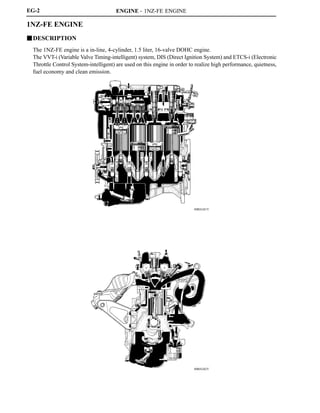
  • 1. ENGINE - 1NZ-FE ENGINE 00REG01Y 00REG02Y EG-2 1NZ-FE ENGINE JDESCRIPTION The 1NZ-FE engine is a in-line, 4-cylinder, 1.5 liter, 16-valve DOHC engine. The VVT-i (Variable Valve Timing-intelligent) system, DIS (Direct Ignition System) and ETCS-i (Electronic Throttle Control System-intelligent) are used on this engine in order to realize high performance, quietness, fuel economy and clean emission.
  • 2. ENGINE - 1NZ-FE ENGINE 247EG02 : IN Opening Angle : EX Opening Angle VVT-i Operation Angle TDC 2_ 7_ 33_ 52_ VVT-i Operation Angle 12_ 42_ BDC EG-3 " Engine Specifications A No. of Cyls. & Arrangement 4-Cylinder, In-line Valve Mechanism 16-Valve DOHC, Chain Drive (with VVT-i) Combustion Chamber Pentroof Type Manifolds Cross-Flow Fuel System SFI Ignition System DIS Displacement cm3 (cu. in.) 1497 (91.3) Bore x Stroke mm (in.) 75.0 x 84.7 (2.95 x 3.33) Compression Ratio 10.5 : 1 Max. Output*1 (SAE-NET) 79 kW @ 6000 rpm (106 HP @ 6000 rpm) Max. Torque*1 (SAE-NET) 139 N.m @ 4200 rpm (103 ft lbf @ 4200 rpm) Intake Open -7 _ - 33_ BTDC Valve Intake Close 52_ - 12_ ABDCValve Timing Exhaust Open 42_ BBDCg Exhaust Close 2_ ATDC Firing Order 1 - 3 - 4 - 2 Research Octane Number 90 or higher Octane Rating 87 or higher Oil Grade ILSAC Tailpipe Emission Regulation TIRE2, ULEV-II Evaporative Emission Regulation ORVR Engine Service Mass*2 kg (lb) M/T 83.2 (183.4)Engine Service Mass (Reference) kg (lb) A/T 77.8 (171.5) *1: Maximum output and torque rating is determined by revised SAE J1349 standard. *2: Weight shows the figure with the oil fully filled. " Valve Timing A
  • 3. ENGINE - 1NZ-FE ENGINEEG-4 JFEATURES OF 1NZ-FE ENGINE The 1NZ-FE engine has been able to achieve the following performance through the adoption of the items listed below. (1) High performance and fuel economy (2) Low noise and vibration (3) Lightweight and compact design (4) Good serviceability (5) Clean emission Section Item (1) (2) (3) (4) (5) A cylinder block made of aluminum is used. f Engine Proper An offset crankshaft is used. f f f Engine Proper The taper squish shape is used for the combustion chamber. f f Valve A timing chain and chain tensioner are used. f f fValve Mechanism The VVT-i system is used. f f Intake manifold made of plastic is used. f The linkless-type throttle body is used. f f Intake and A stainless steel exhaust manifold is used. f Exhaust System Two TWCs (Three Way Catalytic Converter) are used. f A rearward exhaust layout is used to realize the early activation of the catalyst. f 12-hole type injector is used. f f Fuel System The fuel returnless system is used. f f f Fuel System Quick connectors are used to connect the fuel hose with the fuel pipes. f The long-reach type spark plugs are used. f Ignition System The DIS (Direct Ignition system) makes ignition timing adjustment unnecessary. f f f The ETCS-i (Electronic Throttle Control System-intelligent) is used. f f Engine Control The non-contact sensor is used in the throttle position sensor and accelerator pedal position sensor. f Engine Control System The cranking hold function is used. fy Evaporative emission control system is used. f The use of an air fuel ratio sensor allows for precise control. f
  • 4. ENGINE - 1NZ-FE ENGINE 247EG03 EX Injector IN Water Jacket Taper Squish 193EG05247EG04 Bore Center Crankshaft Center Crankshaft Center Maximum Pressure Offset Crankshaft Center Crankshaft EG-5 JENGINE PROPER 1. Cylinder Head D The injectors are installed in the cylinder head to reduce the distance from injector to intake valve, thus it prevents the fuel from adhering to the intake port walls, and reduce exhaust emissions. D The routing of the water jacket in the cylinder head is optimized to achieve high cooling performance. D Through the use of the taper squish combustion chamber, the engine’s knocking resistance and fuel efficiency have been improved. 2. Cylinder Block D Lightweight aluminum alloy is used for the cylinder block. D Through the use of the offset crankshaft, the bore center is shifted 12 mm (0.472 in.) towards the intake, in relation to the crankshaft center. Thus, the side force to cylinder wall is reduced when the maximum pressure is applied, which contributes to fuel economy.
  • 5. ENGINE - 1NZ-FE ENGINE 00REG19Y A A Irregularly shaped outer casting surface of liner Cylinder Block Liner A - A Cross Section 247EG06 Taper Squish Shape Piston Ring EG-6 D The liners are the spiny-type, which have been manufactured so that their casting exterior forms a large irregular surface in order to enhance the adhesion between the liners and the aluminum cylinder block. The enhanced adhesion helps improve heat dissipation, resulting in a lower overall temperature and heat deformation of the cylinder bores. 3. Piston D The piston is made of aluminum alloy D The piston head portion is used a taper squish shape to accomplish fuel combustion efficiency. D Semi floating type piston pins are used. D By increasing the machining precision of the cylinder bore diameter, only one size of piston is available.
  • 6. ENGINE - 1NZ-FE ENGINE 171EG07 Plastic Region Tightening Bolts 171EG08 Crankshaft Position Sensor Rotor Oil Hole Crank Pin No.5 Journal Balance Weight No.4 Journal No.3 JournalNo.2 Journal No.1 Journal EG-7 4. Connecting Rod D The connecting rods and caps are made of high strength steel for weight reduction. D Nutless-type plastic region tightening bolts are used for a light design. 5. Crankshaft D The diameter and width of the pins and journals have been reduced, and the pins for the No.1 and No.4 cylinders have been made highly rigid to realize a lightweight and low-friction performance. D The crankshaft has 5 journals and 4 balance weights. D A crankshaft position sensor rotor is pressed into the crankshaft to realize an integrated configuration.
  • 7. ENGINE - 1NZ-FE ENGINE 165EG12171EG09 Chain Tension Arm Chain Tensioner VVT-i Controller Timing Chain Exhaust Camshaft Intake Camshaft Chain Guide Camshaft Valve Lifter Valve Service Tip The adjustment of the valve clearance is accomplished by selecting and replacing the appropriate valve lifters. Adjusting valve lifters are available in 35 increments of 0.020 mm (0.0008 in.), from 5.060 mm (0.1992 in.), to 5.740 mm (0.2260 in.). For details, refer to 2006 Yaris Repair Manual (Pub. No. RM00R0U). EG-8 JVALVE MECHANISM 1. General D The shimless type valve lifter is used to increase the amount of the valve lift. D The intake and exhaust camshafts are driven by a timing chain. D The VVT-i system is used to realize fuel economy, engine performance and reduce exhaust emissions. For details of VVT-i control, see page EG-41.
  • 8. ENGINE - 1NZ-FE ENGINE 247EG08 VVT-i Controller Exhaust Camshaft Timing Rotor Intake Camshaft Oil Passage (Advance) Oil Passage (Retard) 247EG09 Spring Plunger Cam Cam Spring Check Ball Chain Slipper Timing Chain Chain Damper Oil Jet EG-9 2. Camshaft D Oil passages are provided in the intake camshaft in order to supply engine oil to the VVT-i system. D A VVT-i controller is provided on the front of the intake camshaft to vary the timing of the intake valves. D A Timing rotor is provided behind the intake camshaft to trigger the camshaft position sensor. 3. Timing Chain and Chain Tensioner D A roller type timing chain with an 8.0 mm (0.315 in.) pitch is used to make the engine compact and reduce noise. D The timing chain is lubricated by an oil jet. D The chain tensioner uses a spring and oil pressure to maintain proper chain tensioner at all times. The chain tensioner suppresses noise generated by the timing chain. D A ratchet type non-return mechanism is used in the chain tensioner. " Chain Tensioner A
  • 9. ENGINE - 1NZ-FE ENGINE 171EG32171EG31 Service Hole for Chain Tensioner Front View Oil Pump Back View EG-10 4. Timing Chain Cover D A single-piece, aluminum diecast timing chain cover that entirely seals the front portion of the cylinder block and cylinder head is used. D A service hole for the chain tensioner is provided in the timing chain cover to improve serviceability.
  • 10. ENGINE - 1NZ-FE ENGINE 171EG14 Camshaft Timing Oil Control Valve VVT-i Controller Chain Tensioner Oil Pump Oil Strainer Oil Filter 171EG15 Main Oil Hole Crankshaft Journal Oil Filter Relief Valve Connecting Rod Oil Pump Oil Jet Oil Strainer Piston Oil Jet Cylinder Head Camshaft Timing Oil Control Valve Filter Chain Tensioner Timing Chain Intake Camshaft Journal Exhaust Camshaft Journal Camshaft Timing Oil Control Valve VVT-i Oil Pan EG-11 JLUBRICATION SYSTEM 1. General D The lubrication circuit is fully pressurized and oil passes through an oil filter. D A trochoid gear type oil pump, which is driven directly by the crankshaft, is provided in the front of the cylinder block. D The oil filter is installed diagonally downward from the side of the cylinder block to realize excellent serviceability. D The intake camshaft is provided with a VVT-i controller, and cylinder head is provided with a camshaft timing oil control valve. This system is operated by the engine oil. " Oil Capacity A Liter (US qts, Imp qts) Dry 4.1 (4.3, 3.6) with Oil Filter 3.7 (3.9, 3.3) without Oil Filter 3.4 (3.6, 3.0) " Oil Circuit A
  • 11. ENGINE - 1NZ-FE ENGINE 00REG16Y Water Pump From Radiator To Radiator From Heater Core To Heater Core To Throttle Body 193EG08 Bypass Passage Water Pump Thermostat Cylinder Head Cylinder Block Radiator Throttle Body Heater Core EG-12 JCOOLING SYSTEM D The cooling system is a pressurized, forced-circulation type. D A thermostat with a bypass valve is located on the water inlet housing to maintain suitable temperature distribution in the cooling system. D An aluminum radiator core is used for weight reduction. D The flow of the engine coolant makes a U-turn in the cylinder block to ensure a smooth flow of the engine coolant. D A single cooling fan provides both the cooling and air conditioner performance. D The TOYOTA genuine Super Long Life Coolant (SLLC) is used. " System Diagram A
  • 12. ENGINE - 1NZ-FE ENGINE EG-13 " Engine Coolant Specifications A Engine Coolant Type TOYOTA genuine Super Long Life Coolant (SLLC) or similar high quality ethylene glycol based non-silicate, non-amine, non-nitrite and non-borate coolant with long-life hybrid organic acid technology (coolant with long-life hybrid organic acid technology is a combination of low phosphates and organic acids.) Do not use plain water alone. Color Pink Capacity M/T 4.8 (5.1, 4.2)Capacity Liters (US qts, Imp. qts) A/T 4.7 (5.0, 4.1) Maintenance Intervals First Time 100,000 miles (160,000 km) Maintenance Intervals Subsequent Every 50,000 miles (80,000 km) Thermostat Opening Temperature _C (_F) 80 - 84 (176 - 183) D SLLC is pre-mixed (the U.S.A. models: 50 % coolant and 50 % deionized water, the Canada. models: 55 % coolant and 45 % deionized water). Therefore, no dilution is needed when SLLC in the vehicle is added or replaced. D If LLC is mixed with SLLC, the interval for LLC (ever 40,000 km/24,000 miles or 24 months) should be used.
  • 13. ENGINE - 1NZ-FE ENGINE 00REG06Y Exhaust Manifold Intake Manifold Air Cleaner TWCs Sub Muffler Main Muffler EG-14 JINTAKE AND EXHAUST SYSTEM 1. General D A plastic intake manifold is used for weight reduction. D The linkless-type throttle body is used to realize excellent throttle control. D ETCS-i (Electronic Throttle Control System-intelligent) provides excellent throttle control. For details, see page EG-36. D The exhaust pipe uses a ball joint in order to achieve a simple construction and reliability.
  • 14. ENGINE - 1NZ-FE ENGINE 00REG03Y Charcoal Filter Air Cleaner Cap Air Cleaner Element (Nonwovens Fabric) Service Tip The charcoal filter, which is maintenance-free, cannot be removed from the air cleaner cap. 00REG04Y DC Motor Throttle Valve Reduction Gears Throttle Position Sensor EG-15 2. Air Cleaner D A nonwoven, full-fabric type air cleaner element is used. D A charcoal filter, which adsorbs the HC that accumulates in the intake system when the engine is stopped, is used in the air cleaner cap in order to reduce evaporative emissions. 3. Throttle Body D The linkless-type throttle body is used and it realizes excellent throttle control. D A DC motor with excellent response and minimal power consumption is used for the throttle control motor. The ECM performs the duty ratio control of the direction and the amperage of the current that flows to the throttle control motor in order to regulate the opening angle of the throttle valve.
  • 15. ENGINE - 1NZ-FE ENGINE 00REG07Y Mesh Type Gasket 00REG08Y Ball Joint Gasket Ball Joint TWCs Front Pipe Main Muffler Tail Pipe Ball Joint Sub Muffler EG-16 4. Intake Manifold D The intake manifold has been made of plastic to reduce the weight and the amount of heat transferred from the cylinder head. As a result, it has become possible to reduce the intake temperature and improve the intake volumetric efficiency. D A mesh type gasket is used in order to reduce the intake noise. 5. Exhaust Pipe and Muffler A ball joint is used to joint the exhaust manifold to the exhaust front pipe, and the exhaust front pipe to the exhaust tail pipe. As a result, a simple construction and improved reliability have been realized.
  • 16. ENGINE - 1NZ-FE ENGINE 00REG12Y Fuel Pump D Fuel filter D Pressure Regulator D Fuel Sender Gauge D Fuel Cutoff Valve Canister Fuel Tank Quick Connector Injector View from Bottom EG-17 JFUEL SYSTEM 1. General D The fuel returnless system is used to reduce evaporative emissions. D A fuel tank made of multi-layer plastic is used. D A fuel cut control is used to stop the fuel pump when the SRS airbag is deployed in a front or side collision. For details, see page EG-45. D A quick connector is used to connect the fuel pipe with the fuel hose to realize excellent serviceability. D A compact 12-hole type injector is used to ensure the atomization of fuel. D The ORVR (On-Board Refueling Vapor Recovery) system is used. For details, see page EG-46.
  • 17. ENGINE - 1NZ-FE ENGINE 179EG11 To Canister Fuel Cutoff Valve Fuel Filter Fuel Pump Injector Pulsation Damper Delivery Pipe Pressure Regulator Fuel Tank Module Fuel Pump Assembly 00REG13Y Fuel Tank Outside Fuel Tank Inside HDPE (High Density Polyethylene) Regrind Material Adhesive EVOH (Ethylene Vinyl Alcohol Copolymer) Adhesive HDPE (High Density Polyethylene) EG-18 2. Fuel Returnless System This system is used to reduce the evaporative emission. As shown below, integrating the fuel filter, pressure regulator, fuel sender gauge, and fuel cutoff valve with module fuel pump assembly enables to discontinue the return of fuel from the engine area and prevent temperature rise inside the fuel tank. 3. Fuel Tank Low permeability has been realized through the use of the multi-layered plastic fuel tank. This fuel tank consists of six layers using four types of materials.
  • 18. ENGINE - 1NZ-FE ENGINE 165EG25 Camshaft Position Sensor Crankshaft Position Sensor Various Sensor ECM IGT1 IGT2 IGT3 IGT4 IGF +B Ignition Coil (with Igniter) No.1 Cylinder No.2 Cylinder No.3 Cylinder No.4 Cylinder 171EG27 Igniter Iron Core Plug Cap Primary Coil Secondary Coil EG-19 JIGNITION SYSTEM 1. General D A DIS (Direct Ignition System) is used. The DIS in this engine is an independent ignition system, which has one ignition coil for each cylinder. The DIS ensures the ignition timing accuracy, reduces high-voltage loss, and realizes the overall reliability of the ignition system by eliminating the distributor. D The spark plug caps, which connect to the spark plugs, are integrated with the ignition coils. Also, the igniters are enclosed to simplify the system. D Long-reach type iridium-tipped spark plugs are used. " Ignition Coil with Igniter A
  • 19. ENGINE - 1NZ-FE ENGINE 281EG73 Long-Reach Type Conventional Type Iridium Tip EG-20 2. Spark Plug D Long-reach type iridium-tipped spark plugs are used. D Long-reach type of spark plugs allows the area of the cylinder head to receive the spark plugs to be made thick. Thus, the water jacket can be extended near the combustion chamber, which contributes to cooling performance. D Iridium-tipped spark plugs are used to realize a 100,000 km (62,500 mile) maintenance-free operation. By making the center electrode of iridium, the same ignition performance as the platinum-tipped type spark plug and excellent of durability have been realized. " Specification A DENSO SK16R11 NGK IFR5A-11 Plug Gap mm (in.) 1.1 (0.043)
  • 20. ENGINE - 1NZ-FE ENGINE 206EG41206EG40 Stator Segment Conductor Stator Segment Conductor Joined A A Joined Segment Conductor System A - A Cross Section Segment Conductor Type Generator Stator Stator Conductor Wire Conductor Wire B B Wiring System B - B Cross Section Conventional Type Generator Stator Segment Conductor Cross Section 206EG42 Stator of Segment Conductor Type Generator EG-21 JCHARGING SYSTEM D A compact and lightweight segment conductor type generator that generates high amperage output in a highly efficient manner is used as standard equipment. D This generator has a joined segment conductor system, in which multiple segment conductors are welded together to form the stator. Compared to the conventional wiring system, the electrical resistance is reduced due to the shape of the segment conductors, and their arrangement helps to make the generator compact. " Specifications A Type SE08 Rated Voltage 12 V Rated Output 80 A Initial Output Starting Speed 1,250 rpm Max.
  • 21. ENGINE - 1NZ-FE ENGINE 00REG20Y Generator E Regulator B M IG S L Ignition Switch Discharge Warning Light EG-22 " Wiring Diagram A
  • 22. ENGINE - 1NZ-FE ENGINE 271EG38 PS Type (PS1.6) P Type (P0.8) Armature Surface Commutator Permanent Magnet Brush Length EG-23 JSTARTING SYSTEM 1. General D A P (conventional planetary reduction) type starter is used in the models for U.S.A. D A PS (planetary reduction-segment conductor motor) type starter is used in the models for Canada and cold areas of the U.S.A. " Specification A Destination U.S.A. Canada, Cold Areas of U.S.A. Starter Type P Type PS Type Rating Output 0.8 kW 1.6 kW Rating Voltage 12 V z Length*1 mm (in.) 154 (6.1) 133 (5.2) Weight g (lb) 2800 (6.2) z Rotation Direction*2 Clockwise z *1: Length from the mounted area to the rear end of the starter *2: Viewed from Pinion Side
  • 23. ENGINE - 1NZ-FE ENGINE 206EG20 Conventional Type Armature Armature B B A A PS Type Brush Commutator Brush Surface Commutator Square-Shaped Conductor Round-Shaped Conductor A - A Cross Section (PS Type) B - B Cross Section (P Type) 222EG15 Main Magnet Yoke Interpolar Magnet Main Magnet Armature Cross Section of Yoke Magnetic Flux Generated by Interpolar Magnets N S N N S S Magnetic Flux Generated by Relationship Between Main Magnets EG-24 2. PS (Planetary reduction-Segment conductor motor) Type Starter Construction D Instead of constructing the armature coil with P type of round-shaped conductor wires, the PS type starter uses square conductors. With this type of construction, the same conditions that are realized by winding numerous round-shaped conductor wires can be achieved without increasing the mass. As a result, the output torque has been increased, and the armature coil has been made compact. D Because the surface of the square-shaped conductors that are used in the armature coil functions as a commutator, the overall length of the PS type starter has been shortened. D Instead of the field coils used in the P type starter, the PS type starter uses two types of permanent magnets: the main magnets and the interpolar magnets. The main and interpolar magnets are arranged alternately inside the yoke, allowing the magnetic flux that is generated between the main and interpolar magnets to be added to the magnetic flux that is generated by the main magnets. In addition to increasing the amount of magnetic flux, this construction shortens the overall length of the yoke.
  • 24. ENGINE - 1NZ-FE ENGINE EG-25 JENGINE CONTROL SYSTEM 1. General The engine control system for the 1NZ-FE engine has the following systems. System Outline ’06 Model ’05 Model SFI Electronic Fuel Injection An L-type EFI system detects the intake air mass with a hot-wire type air flow meter. f f ESA Electronic Spark Advance Ignition timing is determined by the ECM based on signals from various sensors. The ECM corrects ignition timing in response to engine knocking. f f ETCS-i Electronic Optimally controls the throttle valve opening in accordance with the amount of accelerator pedal effort and the condition of the engine and vehicle. f - Electronic Throttle Control System-intelligent See page EG-36 D A linkless-type is used without an accelerator. D An accelerator pedal position sensor is provided on the accelerator pedal. D A non-contact type throttle position sensor and accelerator pedal position sensor are used. f - VVT-i Variable Valve Timing-intelligent See page EG-41 Controls the intake camshaft to optimal valve timing in accordance with the engine condition. f f Fuel Pump Control See page EG-45 D Fuel pump operation is controlled by signals from the ECM. D The operation of the fuel pump will stop when the airbag is deployed. f f Air Fuel Ratio Sensor and Oxygen Sensor Heater Control Maintains the temperature of the air fuel ratio sensor or oxygen sensor at an appropriate level to realize accuracy of detection of the oxygen concentration in the exhaust gas. f - Oxygen Sensor Heater Control Maintains the temperature of the oxygen sensor at an appropriate level to realize accuracy of detection of the oxygen concentration in the exhaust gas. - f The ECM controls the purge flow of evaporative emissions (HC) in the canister in accordance with engine conditions. f f Evaporative Emission Using 3 VSVs and a vapor pressure sensor, the ECM detects any evaporative emission leakage occurring between the fuel tank and charcoal canister through changes in the fuel tank pressure. - f Control See page EG-46 Approximately five hours after the ignition switch has been turned OFF, the ECM operates the canister pump module to detect any evaporative emission leakage occurring in the evaporative emission control system through changes in the reference orifice pressure. f - Air Conditioner Cut-off Control*1 By turning the air conditioner compressor OFF in accordance with the engine condition, drivadility is maintained. f f Cooling Fan Control See page EG-56 Cooling fan operation is controlled by signals from ECM based on the engine coolant temperature sensor signal (THW). f f *1: for Models with Air Conditioning System
  • 25. ENGINE - 1NZ-FE ENGINEEG-26 System Outline ’06 Model ’05 Model Starter Control Cranking Hold Function See Page EG-57 Once the ignition switch is turned to the START position, this control continues to operate the starter until the engine is started. f - Engine Immobilizer*2 Prohibits fuel delivery and ignition if an attempt is made to start the engine with an invalid ignition key. f f Diagnosis See Page EG-59 When the ECM detects a malfunction, the ECM diagnoses and memorizes the failed section. f f Fail-Safe See Page EG-59 When the ECM detects a malfunction, the ECM stops or controls the engine according to the data already in memory. f f *2: for Models with Engine Immobilizer System
  • 26. ENGINE - 1NZ-FE ENGINE 00REG10Y SENSORS ACTUATORS MASS AIR FLOW METER INTAKE AIR TEMPERATURE SENSOR CRANKSHAFT POSITION SENSOR CAMSHAFT POSITION SENSOR THROTTLE POSITION SENSOR ENGINE COOLANT TEMPERATURE SENSOR ACCELERATOR PEDAL POSITION SENSOR KNOCK SENSOR IGNITION SWITCH D Ignition Signal D Start Signal PARK/NEUTRAL POSITION SWITCH*1 D Shift Lever Position Signal COMBNATION METER D Vehicle Speed Signal AIR FUEL RATIO SENSOR (Bank 1, Sensor 1) HEATED OXYGEN SENSOR (Bank 1, Sensor 2) SFI No.1 INJECTOR No.2 INJECTOR No.3 INJECTOR No.4 INJECTOR ESA IGNITION COIL with IGNITER SPARK PLUGS VVT-i CAMSHAFT TIMING OIL CONTROL VALVE ETCS- i THROTTLE CONTROL MOTOR FUEL PUMP CONTROL CIRCUIT OPENING RELAY A/F SENSOR & OXYGEN SENSOR HEATER CONTROL A/F SENSOR HEATER Bank 1, Sensor 1 OXYGEN SENSOR HEATER Bank 1, Sensor 2 VG THA NE G2 VTA1 VTA2 THW VPA VPA2 KNK1 IGSW STSW, STA P,N,D R,L,2 SPD A1A+ OX1B ECM #10 #20 #30 #40 IGT1 IGT4 IGF OC1 M FC HT1A HT1B EG-27 2. Construction The configuration of the engine control system in the 1NZ-FE engine is shown in the following chart. (Continued) *1: for Automatic Transaxle Models
  • 27. ENGINE - 1NZ-FE ENGINE 00REG11Y CANISTER PUMP MODULE CANISTER PRESSURE SENSOR TAILLIGHT SWITCH DEFOGGER SWITCH STOP LIGHT SWITCH GENERATOR SHIFT LOCK ECU TRANSPONDER KEY ECU*2 DLC3 AIRBAG SENSOR ASSEMBLY A/C ECU*3 SKID CONTROL ECU*4 BATTERY EVAPORATIVE EMISSION CONTROL CANISTER PUMP MODULE LEAK DETECTION PUMP VENT VALVE PURGE VSV STATER CONTROL STARTER RELAY ACC CUT RELAY COOLING FAN CONTROL COOLING FAN RELAY No.1 COOLING FAN RELAY No.2 EFI MAIN RELAY COMBNATION METER MIL PPMP ELS1 ELS3 STP ALT 3 IMI IMO TC CANH, CANL BATT MPMP VPMP PRG STAR ACCR FAN L FAN H MREL +B W ECM EG-28 *2: for Models with Engine Immobilizer System *3: for Models with Air Conditioning System *4: for ABS Models
  • 28. ENGINE - 1NZ-FE ENGINE 00REG14Y Accelerator Pedal Position Sensor Generator MIL DLC3 Park/Neutral Position Switch* Ignition Switch Circuit Opening Relay ECM Battery Throttle Position Sensor Throttle Control Motor Purge VSV Mass Air Flow Meter D Intake Air Temperature Sensor Camshaft Position Sensor Ignition Coil with Igniter Injector Knock Sensor Engine Coolant Temperature Sensor Canister Filter Fuel Pump Crankshaft Position Sensor TWCs Canister Pump Module D Vent Valve D Leak Detection Pump D Canister Pressure Sensor Heated Oxygen Sensor (Bank 1, Sensor 2) Air Fuel Ratio Sensor (Bank 1, Sensor 1) EG-29 3. Engine Control System Diagram *: for Automatic Transaxle Models.
  • 29. ENGINE - 1NZ-FE ENGINE 00REG15Y Canister Pump Module D Vent Valve D Leak Detection Pump D Canister Pressure Sensor Heated Oxygen Sensor (Bank 1, Sensor 2) ECM VSV (for EVAP) Mass Air Flow Meter (Built-in Intake Air Temperature Sensor) Accelerator Pedal Position Sensor DLC3 Fuel Pump Camshaft Timing Oil Control Valve Ignition Coil with Igniter Camshaft Position Sensor Engine Coolant Temperature Sensor Air Fuel Ratio Sensor (Bank 1, Sensor 1) Injector Knock Sensor Crankshaft Position Sensor Throttle Body EG-30 4. Layout of Main Components
  • 30. ENGINE - 1NZ-FE ENGINE EG-31 5. Main components of Engine Control System General The main components of the 1NZ-FE engine control system are as follows: Components Outline Quantity Function ECM 32-bit CPU 1 The ECM optimally controls the SFI, ESA, and IAC to suit the operating conditions of the engine in accordance with the signals provided by the sensors. Air Fuel Ratio Sensor (Bank 1, Sensor 1) Planar Type with Heater 1 As with the heated oxygen sensor, this sensor detects the oxygen concentration in the exhaust emission. However, it detects the oxygen concentration in the exhaust emission linearly. Heated Oxygen Sensor (Bank 1, Sensor 2) Cup Type with Heater 1 This sensor detects the oxygen concentration in the exhaust emission by measuring the electromotive force which is generated in the sensor itself. Mass Air Flow Meter Hot-wire Type 1 This sensor has a built-in hot-wire to directly detect the intake air mass. Crankshaft Position Sensor (Rotor Teeth) Pickup Coil Type (36-2) 1 This sensor detects the engine speed and performs the cylinder identification. Camshaft Position Sensor (Rotor Teeth) Pickup Coil Type (3) 1 This sensor performs the cylinder identification. Engine Coolant Temperature Sensor Thermistor Type 1 This sensor detects the engine coolant temperature by means of an internal thermistor. Intake Air Temperature Sensor Thermistor Type 1 This sensor detects the intake air temperature by means of an internal thermistor. Knock Sensor Non-resonant Flat Type 1 This sensor detects an occurrence of the engine knocking indirectly from the vibration of the cylinder block caused by the occurrence of engine knocking. Throttle Position Sensor Non-contact Type 1 This sensor detects the throttle valve opening angle. Accelerator Pedal Position Sensor Non-contact Type 1 This sensor detects the amount of pedal effort applied to the accelerator pedal. Injector 12-Hole Type 4 The injector is an electromagnetically-operated nozzle which injects fuel in accordance with signals from the ECM. ECM The 32-bit CPU of the ECM is used to realize the high speed for processing the signals.
  • 31. ENGINE - 1NZ-FE ENGINE 00REG21Y D13N11 Air Fuel Ratio Sensor A1A+ (3.3V) A1A- (2.9V) ECM Air Fuel Ratio Sensor Circuit Heated Oxygen Sensor Circuit Heated Oxygen Sensor OX1B EX1B ECM 4.2 2.2 1 0.1 Air Fuel Ratio Sensor Output (V)* Heated Oxygen Sensor Output (V) 11 (Rich) 14.7 Air Fuel Ratio 19 (Lean) : Air Fuel Ratio Sensor : Heated Oxygen Sensor EG-32 Air Fuel Ratio Sensor and Heated Oxygen Sensor 1) General D The air fuel ratio sensor and heated oxygen sensor differ in output characteristics. D Approximately 0.4V is constantly applied to the air fuel ratio sensor, which outputs an amperage that varies in accordance with the oxygen concentration in the exhaust emission. The ECM converts the changes in the output amperage into voltage in order to linearly detect the present air-fuel ratio. D The output voltage of the heated oxygen sensor changes in accordance with the oxygen concentration in the exhaust emission. The ECM uses this output voltage to determine whether the present air-fuel ratio is richer or leaner than the stoichiometric air-fuel ratio. *: This calculation value is used internally in the ECM, and is not an ECM terminal voltage.
  • 32. ENGINE - 1NZ-FE ENGINE 271EG45 Alumina Dilation Layer Alumina Atmosphere Platinum Electrode Heater Sensor Element (Zirconia) Heater Platinum Electrode Atmosphere Sensor Element (Zirconia) Planer Type Air Fuel Ratio Sensor Cup Type Heated Oxygen Sensor 204EG54 Temperature Sensing Element Platinum Hot-wire Element Air Flow Intake Air Temperature Sensor EG-33 2) Construction D The basic construction of the air fuel ratio sensor and heated oxygen sensor is the same. However, they are divided into the cup type and the planar type, according to the different types of heater construction that are used. D The cup type sensor contains a sensor element that surrounds a heater. D The planer type sensor uses alumina, which excels in heat conductivity and insulation, to integrate a sensor element with a heater, thus realizing the excellent warm-up performance of the sensor. Warm-up Specification A Sensor Type Planer Cup Type Warm-up Time Approx. 10 sec. Approx. 30 sec. Mass Air Flow Meter D The compact and lightweight mass air flow meter, which is a plug-in type, allows a portion of the intake air to flow through the detection area. By directly measuring the mass and the flow rate of the intake air, the detection precision is ensured and the intake air resistance is reduced. D This mass air flow meter has a built-in intake air temperature sensor.
  • 33. ENGINE - 1NZ-FE ENGINE 00REG09Y 230LX12 238EG79 Throttle Body Throttle Position Sensor Portion Magnetic Yoke Hall IC Cross Section Throttle Position Sensor Magnetic Yoke Hall IC Hall IC VTA1 E VC VTA2 ECM Output Voltage V 0 5 Throttle Valve Fully Close Throttle Valve Fully Open 90_ Throttle Valve Opening Angle VTA2 VTA1 Service Tip The inspection method differs from the conventional contact type throttle position sensor because this non-contact type sensor uses a Hall IC. For details, refer to the 2006 Yaris Repair Manual (Pub. No. RM00R0U). EG-34 Throttle Position Sensor The throttle position sensor is mounted on the throttle body to detect the opening angle of the throttle valve. The throttle position sensor converts the magnetic flux density that changes when the magnetic yoke (located on the same axis as the throttle shaft) rotates around the Hall IC into electric signals to operate the throttle control motor.
  • 34. ENGINE - 1NZ-FE ENGINE 00SEG39Y 228TU25228TU24 A A Internal Construction Accelerator Pedal Arm Magnetic Yoke Hall IC A - A Cross Section Accelerator Pedal Position Sensor Magnetic Yoke Hall IC Hall IC VPA EPA VCPA VPA2 EPA2 VCP2 ECM V 5 0 Output Voltage Fully Close Fully Open Accelerator Pedal Depressed Angle VPA2 VPA 90_ Service Tip The inspection method differs from the conventional contact type accelerator pedal position sensor because this non-contact type sensor uses a Hall IC. For details, refer to the 2006 Yaris Repair Manual (Pub. No. RM00R0U). EG-35 Accelerator Pedal Position Sensor The non-contact type accelerator pedal position sensor used a Hall IC. D The magnetic yoke that is mounted at the accelerator pedal arm rotates around the Hall IC in accordance with the amount of effort that is applied to the accelerator pedal. The Hall IC converts the changes in the magnetic flux that occur at that time into electrical signals, and outputs them as of accelerator pedal effort to the ECM. D The Hall IC contains circuits for the main and sub signals. It converts the accelerator pedal depressing angles into electric signals with two differing characteristics and outputs them to the ECM.
  • 35. ENGINE - 1NZ-FE ENGINE 00REG17Y Accelerator Pedal Position Sensor Throttle Valve Throttle Position Sensor Throttle Control Motor Mass Air Flow Meter ECM Skid Control ECU* Ignition Coil Fuel Injector : CAN EG-36 6. ETCS-i (Electronic Throttle Control System-i) General D The ETCS-i is used, providing excellent throttle control in all the operating ranges. D The accelerator cable has been discontinued, and an accelerator pedal position sensor has been provided on the accelerator pedal. D In the conventional throttle body, the throttle valve opening is determined invariably by the amount of the accelerator pedal effort. In contrast, the ETCS-i uses the ECM to calculate the optimal throttle valve opening that is appropriate for the respective driving condition and uses a throttle control motor to control the opening. D The ETCS-i controls the IAC (Idle Air Control) system and cruise control system. D In case of an abnormal condition, this system switches to the limp mode. System Diagram A *: for ABS Models
  • 36. ENGINE - 1NZ-FE ENGINE 00REG05Y Throttle Body Throttle Position Sensor Portion Throttle Control Motor A Reduction Gears View from A Throttle Valve Cross Section Magnetic Yoke Hall IC (for Throttle Position Sensor) Throttle Control Motor EG-37 Construction 1) Throttle Position Sensor The throttle position sensor is mounted on the throttle body to detect the opening angle of the throttle valve. For details, refer to Main Components of Engine Control System section on page EG-34. 2) Throttle Control Motor A DC motor with excellent response and minimal power consumption is used for the throttle control motor. The ECM performs the duty ratio control of the direction and the amperage of the current that flows to the throttle control motor in order to regulate the opening of the throttle valve. Operation 1) General The ECM drives the throttle control motor by determining the target throttle valve opening in accordance with the respective operating condition. D Non-Linear Control D Idle Air Control
  • 37. ENGINE - 1NZ-FE ENGINE 005EG13Y Vehicle’s Longitudinal G Throttle Valve Opening Angle Accelerator Pedal Depressed Angle 0 0 0 : with Control : without Control Time ! EG-38 2) Non-Linear Control It controls the throttle to an optimal throttle valve opening that is appropriate for the driving condition such as the amount of the accelerator pedal effort and the engine speed in order to realize excellent throttle control and comfort in all operating ranges. Control Examples During Acceleration and Deceleration A 3) Idle Air Control The ECM controls the throttle valve in order to constantly maintain an ideal idle speed.
  • 38. ENGINE - 1NZ-FE ENGINE 199EG45 ECM Accelerator Pedal Position Sensor Main Sub Accelerator Pedal Throttle Body Open Main Sub Throttle Position Sensor Throttle Valve Return Spring Throttle Control Motor 199EG46 ECM Accelerator Pedal Position Sensor Main Sub Accelerator Pedal Throttle Body Main Sub Throttle Position Sensor Throttle Valve Return Spring Throttle Control Motor Close by Return Spring EG-39 Fail-Safe of Accelerator Pedal Position Sensor D The accelerator pedal position sensor is comprised of two (main, sub) sensor circuits. If a malfunction occurs in either one of the sensor circuits, the ECM detects the abnormal signal voltage difference between these two sensor circuits and switches to the limp mode. In the limp mode, the remaining circuit is used to calculate the accelerator pedal depressed angle, in order to operate the vehicle under limp mode control. D If both circuits have malfunctions, the ECM detects the abnormal signal voltage from these two sensor circuits and discontinues the throttle control. At this time, the vehicle can be driven within its idling range.
  • 39. ENGINE - 1NZ-FE ENGINE 199EG47 ECM Accelerator Pedal Position Sensor Main Sub Accelerator Pedal Throttle Body Main Sub Throttle Position Sensor Throttle Valve Return Spring Throttle Control Motor Injectors Ignition Coil Return to Prescribed Angle EG-40 Fail-Safe of Throttle Position Sensor D The throttle position sensor is comprised of two (main, sub) sensor circuits. If a malfunction occurs in either one or both of the sensor circuits, the ECM detects the abnormal signal voltage difference between these two sensor circuits, cuts off the current to the throttle control motor, and switches to the limp mode. Then, the force of the return spring causes the throttle valve to return and stay at the prescribed opening angle. At this time, the vehicle can be driven in the limp mode while the engine output is regulated through the control of the fuel injection (intermittent fuel-cut) and ignition timing in accordance with the accelerator opening. D The same control as above is effected if the ECM detects a malfunction in the throttle control motor system.
  • 40. ENGINE - 1NZ-FE ENGINE 247EG23 Camshaft Timing Oil Control Valve Throttle Position Sensor Camshaft Position Sensor Engine Coolant Temperature Sensor ECM Mass Air Flow Meter Crankshaft Position Sensor 221EG16 Crankshaft Position Sensor Mass Air Flow Meter Engine Coolant Temp. Sensor Camshaft Position Sensor Vehicle Speed Sensor Throttle Position Sensor Target Valve Timing Duty-cycle Control Feedback Correction Actual Valve Timing Camshaft Timing Oil control Valve EG-41 7. VVT-i (Variable Valve Timing-intelligent) System General D The VVT-i system is designed to control the intake camshaft within a range of 40_ (of Crankshaft Angle) to provide valve timing that is optimally suited to the engine condition. This realizes proper torque in all the speed ranges as well as realizing excellent fuel economy, and reducing exhaust emissions. D Using the engine speed signal, vehicle speed signal, and the signals from mass air flow meter, throttle position sensor and water temperature sensor, the engine ECU can calculate optimal valve timing for each driving condition and controls the camshaft timing oil control valve. In addition, the engine ECU uses signals from the camshaft position sensor and crankshaft position sensor to detect the actual valve timing, thus providing feedback control to achieve the target valve timing.
  • 41. ENGINE - 1NZ-FE ENGINE TDC EX BDC IN Latest Timing to Advance Side EX IN EX IN EX IN EX IN EX IN to Advance Side to Retard Side Latest Timing Latest Timing 188EG51 227EG40 227EG40 287EG34 188EG51 188EG51 Eliminating overlap to reduce blow back to the intake side Increasing overlap to increase internal EGR to reduce pumping loss Advancing the intake valve close timing for volumetric efficiency improvement Retarding the intake valve close timing for volumetric efficiency improvement Eliminating overlap to prevent blow back to the intake side leads to the lean burning condition, and stabilizes the idling speed at fast idle Eliminating overlap to reduce blow back to the intake side EG-42 Effectiveness of the VVT-i System Operation State Objective Effect D During Idling D At Light Load D Stabilized idling rpm D Better fuel economy At medium Load D Better fuel economy D Improved emission control In Low to Medium Speed Range with Heavy Load Improved torque in low to medium speed range In High Speed Range with Heavy Load Improved output At Low Temperature D Stabilized fast idle rpm D Better fuel economy D Upon Starting D Stopping the Engine Improved startability
  • 42. ENGINE - 1NZ-FE ENGINE 169EG36 Housing Lock Pin Intake Camshaft Vane (Fixed on Intake Camshaft) Oil Pressure At a Stop In Operation Lock Pin 221EG17 to VVT-i Controller (Advance Side) Sleeve Spring Drain Oil Pressure Drain to VVT-i Controller (Retard Side) Spool Valve Coil Plunger EG-43 Construction 1) VVT-i Controller This controller consists of the housing driven from the timing chain and the vane coupled with the intake camshaft. The oil pressure sent from the advance or retard side path at the intake camshaft causes rotation in the VVT-i controller vane circumferential direction to vary the intake valve timing continuously. When the engine is stopped, the intake camshaft will be in the most retarded state to ensure startability. When hydraulic pressure is not applied to the VVT-i controller immediately after the engine has been started, the lock pin locks the movement of the VVT-i controller to prevent a knocking noise. 2) Camshaft Timing Oil Control Valve This camshaft timing oil control valve controls the spool valve position in accordance with the duty-cycle control from the ECM. This allows hydraulic pressure to be applied to the VVT-i controller advance or retard side. When the engine is stopped, the camshaft timing oil control valve is in the most retarded state.
  • 43. ENGINE - 1NZ-FE ENGINE 198EG35 Vane Rotation Direction IN Drain Oil Pressure ECM 198EG36 Vane Rotation Direction Drain IN Oil Pressure ECM EG-44 Operation 1) Advance When the camshaft timing oil control valve is operated as illustrated below by the advance signals from the ECM, the resultant oil pressure is applied to the timing advance side vane chamber to rotate the camshaft in the timing advance direction. 2) Retard When the camshaft timing oil control valve is operated as illustrated below by the retard signals from the ECM, the resultant oil pressure is applied to the timing retard side vane chamber to rotate the camshaft in the timing retard direction. 3) Hold After reaching the target timing, the valve timing is held by keeping the camshaft timing oil control valve in the neutral position unless the traveling state changes. This adjusts the valve timing at the desired target position and prevents the engine oil from running out when it is unnecessary.
  • 44. ENGINE - 1NZ-FE ENGINE 00REG18Y Front Airbag Sensor (RH and LH) Curtain Shield Airbag Sensor Assembly* (RH and LH) : CAN Airbag Sensor Assembly Side Airbag Sensor Assembly* (RH or LH) ECM Circuit Opening Relay From Battery Fuel Pump Motor *: Option Equipment EG-45 8. Fuel Pump Control A fuel cut control is used to stop the fuel pump when the SRS airbag is deployed at the front, side or rear side collision. In this system, the airbag deployment signal from the airbag assembly is detected by the ECM, and it turns OFF the circuit opening relay. After the fuel cut control has been activated, turning the ignition switch from OFF to ON cancels the fuel cut control, thus can be restarted.
  • 45. ENGINE - 1NZ-FE ENGINE Service Tip The canister pump module performs fuel evaporative emission leakage check. This check is done approximately five hours after the engine is turned off. So you may hear sound coming from underneath the luggage compartment for several minutes. It does not indicate a malfunction. D The pinpoint pressure test procedure is carried out by pressurizing the fresh air line that runs from the pump module to the air filler neck. For details, see the 2006 Yaris Repair Manual (Pub. No. RM00R0U). EG-46 9. Evaporative Emission Control System General The evaporative emission control system prevents the vapor gas that is created in the fuel tank from being released directly into the atmosphere. D The canister stores the vapor gas that has been created in the fuel tank. D The ECM controls the purge VSV in accordance with the driving conditions in order to direct the vapor gas into the engine, where it is burned. D In this system, the ECM checks the evaporative emission leak and outputs DTC (Diagnostic Trouble Codes) in the event of a malfunction. An evaporative emission leak check consists of an application of a vacuum pressure to the system and monitoring the changes in the system pressure in order to detect a leakage. D This system consists of the purge VSV, canister, refueling valve, canister pump module, and ECM. D The ORVR (Onboard Refueling Vapor Recovery) function is provided in the refueling valve. D The canister pressure sensor has been included to the canister pump module. D The canister filter has been provided on the fresh air line. This canister filter is maintenance-free. D The followings are the typical conditions for enabling an evaporative emission leak check: Typical Enabling Condition D Five hours have elapsed after the engine has been turned OFF*. D Altitude: Below 2400 m (8000 feet) D Battery voltage: 10.5 V or more D Ignition switch: OFF D Engine coolant temperature: 4.4 to 35_C (40 to 95_F) D Intake air temperature: 4.4 to 35_C (40 to 95_F) *: If engine coolant temperature does not drop below 35_C (95_F), this time should be extended to 7 hours. Even after that, if the temperature is not less than 35_C (95_F), the time should be extended to 9.5 hours.
  • 46. ENGINE - 1NZ-FE ENGINE 00REG22Y To Intake Manifold Purge VSV Purge Air Line Fresh Air Line Fuel Tank Canister Filter ECM Canister Pump Module Leak Detection Pump Pump Motor Canister Pressure Sensor Refueling Valve Vent Valve Canister M P EG-47 System Diagram Function of Main Components Component Function Canister Contains activated charcoal to absorb the vapor gas that is created in the fuel tank. Refueling Controls the flow rate of the vapor gas from the fuel tank to the canister when the system is purging or during refueling.Refueling Valve Restrictor Passage Prevents a large amount of vacuum during purge operation or system monitoring operation from affecting the pressure in the fuel tank. Fresh Air Line Fresh air goes into the canister and the cleaned drain air goes out into the atmosphere. C i t Vent Valve Opens and closes the fresh air line in accordance with the signals from the ECM. Canister Pump Module Leak Detection Pump Applies vacuum pressure to the evaporative emission system in accordance with the signals from the ECM. Module Canister Pressure Sensor Detects the pressure in the evaporative emission system and sends the signals to the ECM. Purge VSV Opens in accordance with the signals from the ECM when the system is purging, in order to send the vapor gas that was absorbed by the canister into the intake manifold. In system monitoring mode, this valve controls the introduction of the vacuum into the fuel tank. Canister Filter Prevents dust and debris in the fresh air from entering the system. ECM Controls the canister pump module and purge VSV in accordance with the signals from various sensors, in order to achieve a purge volume that suits the driving conditions. In addition, the ECM monitors the system for any leakage and outputs a DTC if a malfunction is found.
  • 47. ENGINE - 1NZ-FE ENGINE D13N07285EG76 Chamber A Fresh Air Line Refueling Valve (Open) Chamber B From Fuel Tank Internal Pressure Canister During Refueling To Fuel Tank Positive Pressure (Fuel Tank Pressure) Restrictor Passage Negative Pressure (Intake Manifold Pressure) During Purge Operation or System Monitoring Operation 228TU119 Fuel Tank Cap Fresh Air Fuel Inlet Pipe To Canister Cleaned Drain Air EG-48 Construction and Operation 1) Refueling Valve The refueling valve consists of chamber A, chamber B, and the restrictor passage. A constant atmospheric pressure is applied to chamber A. D During refueling, the internal pressure of the fuel tank increases. This pressure causes the refueling valve to lift up, allowing the fuel vapors to enter the canister. D The restrictor passage prevents the large amount of vacuum that is created during purge operation or system monitoring operation from entering the fuel tank, and limits the flow of the vapor gas from the fuel tank to the canister. If a large volume of vapor gas recirculates into the intake manifold, it will affect the air-fuel ratio control of the engine. Therefore, the role of the restrictor passage is to help prevent this from occurring. 2) Fuel Inlet (Fresh Air Line) In accordance with the change of structure of the evaporative emission control system, the location of a fresh air line inlet has been changed from the air cleaner section to the near fuel inlet. The flesh air from the atmosphere and drain air cleaned by the canister will go in and out of the system through the passage shown below.
  • 48. ENGINE - 1NZ-FE ENGINE 279EG26 Fresh Air Canister Pressure Sensor Canister Pressure Sensor Leak Detection Pump D Pump Motor D Vane Pump Vent Valve Canister Fresh Air 279EG25 D13N17 Canister Pump Module Vent Valve Fresh Air Filter Filter M Leak Detection Pump Pump Motor P Canister Pressure Sensor Filter Reference Orifice [0.5 mm, (0.020 in) Diameter] To Canister EG-49 3) Canister Pump Module Canister Pump module consists of the vent valve, leak detection pump, and canister pressure sensor. D The vent valve switches the passages in accordance with the signals received from the ECM. D A DC type brush less motor is used for the pump motor. D A vane type vacuum pump is used. Simple Diagram A
  • 49. ENGINE - 1NZ-FE ENGINE 00REG23Y To Intake Manifold Atmosphere Purge VSV (Open) ECM 00REG24Y Close Open EG-50 System Operation 1) Purge Flow Control When the engine has reached predetermined parameters (closed loop, engine coolant temperature above 74_C (165_F), etc.), stored fuel vapors are purged from the canister whenever the purge VSV is opened by the ECM. The ECM will change the duty ratio cycle of the purge VSV, thus controlling purge flow volume. Purge flow volume is determined by intake manifold pressure and the duty ratio cycle of the purge VSV. Atmospheric pressure is allowed into the canister to ensure that purge flow is constantly maintained whenever purge vacuum is applied to the canister. 2) ORVR (On-Board Refueling Vapor Recovery) When the internal pressure of the fuel tank increases during refueling, this pressure causes the diaphragm in the refueling valve to lift up, allowing the fuel vapors to enter the canister. Because the vent valve is always open (even when the engine is stopped) when the system is in a mode other than the monitoring mode, the air that has been cleaned through the canister is discharged outside the vehicle via the fresh air line. If the vehicle is refueled in the monitoring mode, the ECM will recognize the refueling by way of the canister pressure sensor, which detects the sudden pressure increase in the fuel tank, and will open the vent valve.
  • 50. ENGINE - 1NZ-FE ENGINE D13N20 Purge VSV ON (Open) OFF (Close) Vent Valve ON OFF (Vent) ON OFF Atmospheric Pressure Pump Motor System Pressure 0.02 in. Pressure 1) 2) 3) 4) 5) EG-51 3) EVAP Leak Check a. General The EVAP leak check operates in accordance with the following timing chart: Timing Chart A Order Operation Description Time 1) Atmospheric Pressure Measurement ECM turns vent valve OFF (vent) and measures EVAP system pressure to memorize atmospheric pressure. 10 sec. 2) 0.02 in. Leak Pressure Measurement Leak detection pump creates negative pressure (vacuum) through 0.02 in. orifice and the pressure is measured. ECM determines this as 0.02 in. leak pressure. 60 sec. 3) EVAP Leak Check Leak detection pump creates negative pressure (vacuum) in EVAP system and EVAP system pressure is measured. If stabilized pressure is larger than 0.02 in. leak pressure, ECM determines EVAP system has a leakage. If EVAP pressure does not stabilize within 12 minutes, ECM cancels EVAP monitor. Within 12 min. 4) Purge VSV Monitor ECM opens purge VSV and measure EVAP pressure increase. If increase is large, ECM interprets this as normal. 10 sec. 5) Final Check ECM measures atmospheric pressure and records monitor result. —
  • 51. ENGINE - 1NZ-FE ENGINE 00REG25Y D13N22 Atmosphere Purge VSV (OFF) ECM Canister Pump Module Vent Valve (OFF) M Leak Detection Pump Pump Motor P Canister Pressure Sensor ON (Open) OFF (Close) Purge VSV ON OFF (Vent) Vent Valve Pump Motor ON OFF Atmospheric Pressure System Pressure Atmospheric Pressure Measurement EG-52 b. Atmospheric Pressure Measurement 1) When the ignition switch is turned OFF, the purge VSV and vent valve are turned OFF. Therefore, the atmospheric pressure is introduced into the canister. 2) The ECM measures the atmospheric pressure through the signals provided by the canister pressure sensor. 3) If the measurement value is out of standards, the ECM actuates the leak detection pump in order to monitor the changes in the pressure.
  • 52. ENGINE - 1NZ-FE ENGINE 00REG26Y D13N26 Atmosphere Purge VSV (OFF) ECM Canister Pump Module Vent Valve (OFF) M Leak Detection Pump Pump Motor P Canister Pressure Sensor Reference Orifice Purge VSV ON (Open) OFF (Close) ON OFF (Vent) Vent Valve ON OFF Pump Motor Atmospheric Pressure System Pressure 0.02 in. Pressure 0.02 in. Pressure Measurement EG-53 c. 0.02 in. Leak Pressure Measurement 1) The vent valve remains off, and the ECM introduces atmospheric pressure into the canister and actuates the leak detection pump in order to create a negative pressure. 2) At this time, the pressure will not decrease beyond a 0.02 in. pressure due to the atmospheric pressure that enters through a 0.02 in. diameter reference orifice measuring 0.5 mm (0.02 in.). 3) The ECM compares the logic value and this pressure, and stores it as a 0.02 in. leak pressure in its memory. 4) If the measurement value is below the standard, the ECM will determine that the reference orifice is clogged and store DTC (Diagnostic Trouble Code) P043E in its memory. 5) If the measurement value is above the standard, the ECM will determine that a high flow rate pressure is passing through the reference orifice and store DTCs (Diagnostic Trouble Codes) P043F, P2401, P2402, and P2422 in its memory.
  • 53. ENGINE - 1NZ-FE ENGINE 00REG27Y Atmosphere Purge VSV (OFF) ECM Canister Pump Module Vent Valve (ON) M Leak Detection Pump Pump Motor P Canister Pressure Sensor Reference Orifice Vacuum D13N62 OFF (Close) ON (Open) Purge VSV ON OFF (Vent) Vent Valve ON OFF Atmospheric Pressure Pump Motor System Pressure 0.02 in. Pressure EVAP Leak Check P0455 P0456 Normal EG-54 d. EVAP Leak Check 1) While actuating the leak detection pump, the ECM turns ON the vent valve in order to introduce a vacuum into the canister. 2) When the pressure in the system stabilizes, the ECM compares this pressure and the 0.02 in. pressure in order to check for a leakage. 3) If the detection value is below the 0.02 in. pressure, the ECM determines that there is no leakage. 4) If the detection value is above the 0.02 in. pressure and near atmospheric pressure, the ECM determines that there is a gross leakage (large hole) and stores DTC P0455 in its memory. 5) If the detection value is above the 0.02 in. pressure, the ECM determines that there is a small leakage and stores DTC P0456 in its memory.
  • 54. ENGINE - 1NZ-FE ENGINE D13N63 00REG28Y Atmosphere Atmosphere Purge VSV (ON) ECM Canister Pump Module Vent Valve (ON) M Leak Detection Pump Pump Motor P Canister Pressure Sensor ON (Open) OFF (Close) Purge VSV ON OFF (Vent) Vent Valve ON OFF Pump Motor Atmospheric Pressure System Pressure 0.02 in. Pressure Normal Purge VSV Monitor P0441 EG-55 e. Purge VSV Monitor 1) After completing an EVAP leak check, the ECM turns ON (open) the purge VSV with the leak detection pump actuated, and introduces the atmospheric pressure from the intake manifold to the canister. 2) If the pressure change at this time is within the normal range, the ECM determines the condition to be normal. 3) If the pressure is out of the normal range, the ECM will stop the purge VSV monitor and store DTC P0441 in its memory.
  • 55. ENGINE - 1NZ-FE ENGINE 00SEG47Y Engine Coolant Temperature Sensor ECM Cooling Fan Relay No.1 Cooling Fan Motor Cooling Fan Relay No.2 00SEG48Y Engine Coolant Temperature Sensor A/C ECU : CAN ECM Cooling Fan Relay No.1 Cooling Fan Motor Cooling Fan Relay No.2 Resistor (Low Speed Operation) 00SEG81Y *1: Judgmental standard of engine coolant temperature High Low 94.5_C (202.1_F) 96_C (204.8_F) *2: Judgmental standard of refrigerant pressure High Low 1.2 MPa (12.5 kgf/cm2, 178 psi) 1.5 MPa (15.5 kgf/cm2, 220 psi) EG-56 10. Cooling Fan Control D On the models without air conditioning, the ECM controls the operation of the cooling fan based on the engine coolant temperature sensor signal. Wiring Diagram A Cooling Fan Operation A Engine Coolant Temperature Low High Cooling Fan Operation OFF ON D On the models with air conditioning, the ECM controls the operation of the cooling fan in two speeds (Low and Hi) based on the engine coolant temperature sensor signal and the A/C ECU signal. The Low speed operation is accomplished by applying the current through a resistor, which reduces the speed of the cooling fan. Wiring Diagram A Cooling Fan Operation A Engine Coolant Air Conditioning Condition Cooling Fan Operation Engine Coolant Temperature*1 A/C Switch Refrigerant Pressure*2 Cooling Fan Operation OFF Low OFF Low ON Low LowLow ON High High OFF Low High High ON Low Highg ON High High
  • 56. ENGINE - 1NZ-FE ENGINE 00SEG55Y Battery Ignition Switch Starter ACC Cut Relay Ignition Switch D Park/Neutral Position Switch*1 D Clutch Start Switch*2 Starter Relay ECM ACCR STSW STAR STA D Engine Speed Signal D Engine Coolant Temperature Signal EG-57 11. Cranking Hold Function General D Once the ignition switch is turned to the START position, this control continues to operate the starting until the engine starts, without having to hold the ignition switch in the START position. This prevents starting failures and the engine from being cranked after the engine has started. D When the ECM detects a start signal from the ignition switch, this system monitors the engine speed (NE) signal and continues to operate the starter until it determines that the engine has started. System Diagram A *1: for Automatic Transaxle Models *2: for Manual Transaxle Models
  • 57. ENGINE - 1NZ-FE ENGINE 00SEG57Y Ignition Switch Position START ON Starter Relay ON OFF Accessory Power ON OFF Engine Speed Signal (NE) Cranking Limit Approx. 2 - 25 sec. Successful Starting of Engine Failed Starting of Engine ECM determines that the engine has started successfully when the engine speed is approximately 500 rpm. EG-58 Operation D As indicated in the following timing chart, when the ECM detects a start signal from the ignition switch, it energizes the starter relay to operate the starter. If the engine is already running, the ECM will not energize the starter relay. D After the starter operates and the engine speed becomes higher than approximately 500 rpm, the ECM determines that the engine has started and stops the operation of the starter. D If the engine has any failure and does not work, the starter operates as long as its maximum continuous operation time and stops automatically. The maximum continuous operation time is approximately 2 seconds through 25 seconds depending on the engine coolant temperature condition. When the engine coolant temperature is extremely low, it is approximately 25 seconds and when the engine is warmed up sufficiently, it is approximately 2 seconds. D In case that the starter begins to operate, but cannot detect the engine speed signal, the ECM will stop the starter operation immediately. Timing Chart A
  • 58. ENGINE - 1NZ-FE ENGINE Service Tip To clear the DTC that is stored in the ECM, use a hand-held tester or disconnect the battery terminal or remove the EFI fuse for 1 minute or longer. EG-59 12. Diagnosis D When the ECM detects a malfunction, the ECM makes a diagnosis and memorizes the failed section. Furthermore, the MIL (Malfunction Indicator Lamp) in the combination meter illuminates or blinks to inform the driver. D The ECM will also store the DTCs of the malfunctions. D The DTCs can be accessed by the use of the hand-held tester. D To comply with the OBD-II regulations, all the DTCs (Diagnostic Trouble Codes) have been made to correspond to the SAE controller codes. Some of the DTCs have been further divided into smaller detection areas than in the past, and new DTCs have been assigned to them. For details, refer to the 2006 Yaris Repair Manual (Pub. No. RM00R0U). 13. Fail-Safe When a malfunction is detected at any of the sensors, there is a possibility of an engine or other malfunction occurring if the ECM were to continue to control the engine control system in the normal way. To prevent such a problem, the fail-safe function of the ECM either relies on the data stored in memory to allow the engine control system to continue operating, or stops the engine if a hazard is anticipated. For details, refer to the 2006 Yaris Repair Manual (Pub. No. RM00R0U).