1. The secret
behind
mechatronics
Why companies will want
to be part of the revolution
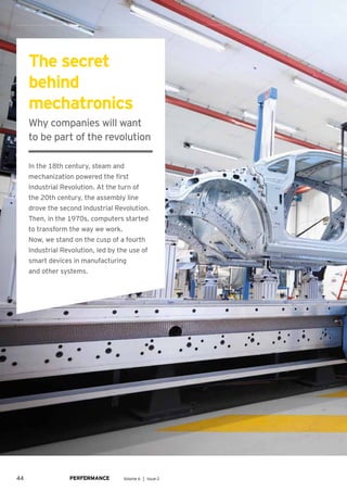
In the 18th century, steam and
mechanization powered the first
Industrial Revolution. At the turn of
the 20th century, the assembly line
drove the second Industrial Revolution.
Then, in the 1970s, computers started
to transform the way we work.
Now, we stand on the cusp of a fourth
Industrial Revolution, led by the use of
smart devices in manufacturing
and other systems.
44 Volume 6 │ Issue 2
2. Authors
Dr. Christoph Kilger
Partner, Advisory - Supply Chain &
Operations Advisory, EY, Germany
Dr. Adrian Reisch
Senior Manager, Advisory - Product
Life Cycle Management, EY, Germany
René Indefrey
Senior Manager, Advisory, EY, Germany
45
3. The secret behind mechatronics. Why companies will want to be part of the revolution
E nterprises around the
world face an extensive
reorganization to meet
the challenges that this
revolution will bring.
This article looks at these
challenges, how organizations can
overcome them and what they can do
to be competitive in the future.
What’s driving the need
for change?
Manufacturing has always relied on
complex machinery that pushes the
boundaries of innovation. This is true
right back to the earliest industrial
revolutions. In recent decades,
traditional manufacturing has become
even more complex with the addition
of software components to plant and
machinery.
For the majority of industrial
companies, the engineering process
involves a sequence of three design
stages. Firstly, the mechanical
engineers will try to interpret what the
sales team has promised the customer
in terms of the machinery they need.
They then hand over their design to the
electrical engineers. This is the second
stage, during which the necessary
electrics and cabling are identified
and incorporated into the design. The
46 Volume 6 │ Issue 2
4. final stage is completed by the software
engineers — it is they who bring the
machine to life.
But this sequential approach carries the
potential for many problems. For example,
what if the mechanical engineers haven’t
fully understood what the customer
wanted? Or what if they have focused
only on the mechanical issues and not
anticipated the potential electrical or
software issues? Information is lost along
the way, leading to the three teams of
engineers having to keep revisiting and
revising their designs. So there is a lot of
extra cost, a long lead time, high levels of
effort and, at the end of the day, a product
that is not of the best quality.
Looking at the whole
To solve these problems, manufacturing
companies need to change their approach
so that, rather than sequential design,
they use a model that allows them to
design the machine as a whole. This
is achieved by setting up a “functional
model” of the machine.
For example, Figure 1 shows the
“Traditional approaches
mean there is a lot
of extra cost, a long
lead time, high levels
of effort and, at the
end of the day, a
product that is not
of the best quality.”
various functions and sub-functions that
might be associated with the production
of a packaging machine. Under traditional,
sequential development, each of these
functions would be designed in isolation
both from each other and also from the
three separate design teams.
But, by using a functional model, this
allows a completely new way of thinking
for engineers. Whereas, previously, they
would have been given a requirement
and made their design accordingly, now
they are given a more complex, functional
picture. This allows them to take into
Figure 1
From idea to product: the various functions and components of design
Product idea Function Sub-function Component Module Product
Packer
Deliverer
Packaging
unit
Safety
equipment
Providing boxes
Supplying glue
Supplying product
Picking product
Putting down
product
Gluing box
Protecting worker
Preventing excess
voltage
Inflow
Conveyor
Grappler
Gluing unit
Rack
Sensor
Emergency
switch
Fuse
Packaging
Supplying
Packaging
Granting
protection
47
5. The secret behind mechatronics. Why companies will want to be part of the revolution
Figure 2
An integrated mechatronics system model enables the collaboration
of all functional units in the development process
Integrated mechatronics
Benefits
1. Uniform terminology
2. Graphical representation of product
structures and architecture
3. Reduced misunderstanding and iteration loops
4. Uniform, standardized product documentation
5. Identification of connections, interdependencies
and similar solutions
6. Improved effectiveness of communication
and collaboration
7. Identification and resolution of design
issues and problems before detailed
design starts
Mechanical
system
system model
Product
manager
Project
manager
Process
technology
Hardware
Usability
Software
Systems
Line
design
Assembly
account not just the requirements for
their own specialist discipline, such as
electrics, but also all the other relevant
requirements associated with the whole
product design. In summary, the purpose
of the functional model is to describe how
the whole thing works together taking
into consideration all the functional units,
as shown in Figure 2.
One of the main advantages of this
functional approach is that it allows you
to look at the design from a “modular
product architecture” perspective.
What this means is that your design is
similar to a series of building blocks. For
example, there may be a function in the
overall model that has already been fully
designed by the mechanical, electrical
and software engineers. You can then
reuse this function or building block
and just adapt it for similar or identical
functions during the design process.
It avoids the need to start each design
element from scratch. The benefit is that
it speeds up the whole design, improving
the chance of a “right first time” product
and allowing you to get it on the market
much more quickly.
The other significant advantage of
this modular approach is that it allows
very high complexity in design, i.e.,
a large variety of products, because you
can combine these building blocks to
produce new products. So, it enables high
“Using a functional
model allows
a completely new
way of thinking
for engineers.”
48 Volume 6 │ Issue 2
6. Figure 3
Replacement of sequential development by a concurrent,
functions-based process
Requirements
Mechanical
development
Hardware
development
Mechanical
development
Hardware
development
Software
development
Software
development
Mechatronics
Sequential
development process
Today
Software system
System theory
Model building
Automation
Software technology
Artificial intelligence
Electronic system
Microelectronics
Power electronics
Sensor system
Actuating elements
Mechanical system
Mechanical engineering
Precision mechanics
Electromechanics
Functional
mode
Future
Mechatronics
development process
variability with low internal complexity
and speed to market — all of which brings
competitive advantage.
New change, new ideas
“Mechatronics” is a relatively new
term — more well known in engineering
circles. It refers to the bringing together
of the three disciplines mentioned
above, i.e., mechanical, electrical and
software. In the past, modular revision
approaches have tended to focus only on
the mechanical aspects. What this article
is proposing is that the focus should
be on all three areas together, i.e., a
mechatronics modularization approach.
Figure 3 shows the three elements
of mechatronics and the transition from
the sequential development process to
a mechatronics approach, as already
described.
There is also a second aspect of
change that will help manufacturing
companies as they begin to work with a
mechatronics development process. This
relates to what is called the “V-model.”
The V-model is an established way of
structuring the product development
processes. It is based on an approach
called “system engineering,” which has, at
its core, a focus on defining the customer
needs and required functionality early
on in the development process. System
engineering is particularly common in the
aviation and aerospace industry, but is
now becoming increasingly used in plant
and machinery engineering.
The system engineering process
model generally consists of three phases:
system design, system development and
system integration. These three phases
can be iteratively run through several
times in a row.
What the authors are proposing is
a more complex V-model that is based
around system engineering. In the past,
the V-model has been very simple, with
a focus on single concepts. You begin by
trying to understand the requirements
(the left “branch” of the V), you design
the mechanics (the bottom branch of the
V) and you bring everything together into
a final product (the right branch of the V).
The V-model on the left of Figure 4 shows
this simple approach.
But the V-model based on system
engineering would be based around
49
7. The secret behind mechatronics. Why companies will want to be part of the revolution
the three phases, with each branch
representing a phase, i.e., the left branch
is phase one: system design, the bottom
is phase two: system development and
the right branch is phase three: system
integration.
Within each phase are the different
streams for mechanics, electronics or
electrical design, software design, usability
design and so on. This has the effect of
forcing the design to focus not just on
one element, but the whole thing. For
example, when the requirements are being
identified, right at the start of the design
process, they will include all aspects of
production rather than just one at a time.
Similarly, as you work through the stages
of the design process, such as functional
description, system design, behavioral
model, test cases and simulation — all
will be carried out with a focus on the
whole product rather than breaking it
into disjointed, sequential and isolated
elements. The diagram shown on the right
of Figure 4 presents this more complex
V-model. The ultimate goal is to describe
the whole machine as one system.
Taking this one step further, the
authors propose a version of system
engineering that is called model-based
system engineering (MBSE). The
difference between MBSE and traditional
system engineering is that MBSE is a
digital model rather than relying on paper
or documents. The model is used as a
means of communication between the
Figure 4
From the incomplete, traditional V-model to the new V-model based on system engineering
Requirements Product Requirements Product
Mechanics
Hardware
Software
Process engineering
Usability
Mechanics -> Hardware
-> Software
Process engineering
Usability
System
design
Single
concepts
Initial
operation
System
integration
Domain-specific design
Domain-specific design
Physical
tests
Physical
tests
Virtual
tests
Hybrid
tests
Model creation and analysis
“The benefit is the whole design is
speeded up, improving the chance
of a ‘right first time’ product and
allowing you to get it on the market
much more quickly.”
50 Volume 6 │ Issue 2
8. developers and the various engineering
disciplines. It contains all the essential
cross-disciplinary information about
the system and describes it in a more
accessible, understandable way.
In order to bring the MBSE system
model to life, the user needs a modeling
language, such as SysML, and a software
tool, such as METUS. Languages and tools
such as these help define correlations
between system requirements, functions,
structure and behavior.
The final piece of the jigsaw is to
identify a methodology for describing
the system model in MBSE. For this, we
propose RFLP (Requirements, Functions,
Logic, Product). Firstly, the customer’s
requirements (R) are structured according
to functional and non-functional aspects.
Next, the functions (F) are defined, which
are then converted into a logic (L) model
and, ultimately, the technical solution,
resulting in the final product (P).
Putting theory into practice
EY recently applied this model to the
existing processes and procedures within
a machinery- and equipment-building
company. The business was a classical
mechanical engineering company using
a sequential approach when developing
new products, i.e., first the mechanical
construction department analyzed the
customer requirements and developed
a solution, then the hardware was
configured and, finally, the automation
software was designed. The aim of
the EY project was to help adapt the
existing process so that the three
disciplines — mechanics, hardware and
software — were developed in parallel.
The MBSE methods were integrated into
the V-model to develop a mechatronics
system approach.
Working with the client, we produced
a detailed development framework
that served as the basis for the project.
Furthermore, a data model was created
to underpin the development framework,
the hardware and software. Finally, the
changes in customer processes and
organization were defined.
Development framework
The design of the development
framework provides a distinction between
the three phases of system engineering,
i.e., system design, system development
and system integration.
During the system design, the
objective is to create a model that works
across all three disciplines (mechanical,
electrical and software), as previously
described. The requirements from each
discipline are collected and organized
in a software tool. The tool helps to
make complex architecture relationships
transparent (see Figure 1). Once the
requirement structure has been created,
this is then passed to a more detailed
software tool, such as SPARX Enterprise,
which classifies the requirements.
51
9. The secret behind mechatronics. Why companies will want to be part of the revolution
“The ultimate goal
is to describe
the whole machine
as one system.”
The next step is the preparation of the
functional model. The overall function
of the product that is being designed is
divided into its sub-functions, each of
that may be further divided into sub-sub-
functions (refer to Figure 1).
The end result of this design phase
(phase one) is a model and description
of the system and its subsystems,
specifications and an overall product
concept, incorporating all relevant
disciplines. It also includes a definition
of which discipline implements which
subsystem in which way.
Following completion of phase one,
we then move to phase two: system
development, during which each of
the individual disciplines carries out
its specific development work. There
is continuous coordination between
the different development streams,
both over time, i.e., status meetings
and milestones, but also as part of the
interface specification between the
individual subsystems.
The result of phase two is individual
components or software that are subject
to first testing (mostly virtual) within their
respective disciplines.
In the final phase (system integration),
the results of the various disciplines are
brought together. This is subject to rigorous
testing to check that the system design
originally specified has been successfully
implemented. The final part of this phase is
a review and approval process.
The benefits of an
integrated approach
The benefits of an integrated product
life cycle management approach come
from spending more effort in the early
phases of design. These benefits can be
summarized as follows:
• Maximized profitability
• Reduced development costs
• Reduced time to market
• Extended product life cycle that is
actively managed
Figure 5 quantifies these benefits in
relation to the client project cited in
this article. In addition to the 15%–20%
reduction in total project costs and 30%–
40% higher probability of keeping to the
launch date, other notable gains included:
• New employees were brought up to
speed (knowledge transfer) more quickly,
by up to 50%.
• Design corrections during the later
development stages were avoided
by up to 80%.
• Reworking and service efforts (e.g.,
warranty and additional work) were
reduced by up to 40%.
The whole concept allows companies to
operate at a much more advanced level in
terms of interdisciplinary developments.
The modeling of the overall system in
Figure 5
Project benefits of a system engineering approach
Efforts (cumulative)
Time
15%–20% reduction
in total project costs
30%–40% higher
probability of meeting
the launch date
Scheduled
production launch
With system
engineering
Without system
engineering
52 Volume 6 │ Issue 2
10. languages such as SysML creates a clear
overall view and communications base
that is understood by all disciplines.
The linking of requirements, function,
logic and product means the company
can more easily estimate and anticipate
the impact of any changes to the overall
product architecture. The time wasted
on expensive investigations into which
complex functions a component needs
can be reduced significantly. In addition,
the structured approach also helps to
meet documentation requirements. In
the life science industry, for example, it
makes it easier to test (and prove) which
requirements are satisfied by which
function and which component.
In the future, it is also conceivable
that companies could further drive the
pricing of individual functions. On the
one hand, this would increase internal
transparency and, on the other, it
would enable companies to inform their
customers about the composition of the
price of the machine they are buying. By
linking the RFLP method, a traceability
of component costs of functions can be
easily carried out.
Furthermore, the approach also has
a positive effect on the diversity of
components. By modeling according
to the RFLP method, it is possible to
perform a functional standardization of
the hardware and thus to specify, per
function, the implementation of one
or more hardware components. This
has a positive impact on service parts
management, since the number of
components that needs to be managed
decreases significantly. This is a factor
that should not to be underestimated,
especially in the area of electronics.
As manufacturing moves into its fourth
Industrial Revolution, businesses need
to be embracing an integrated design
approach so that they are first to market
with their products, while simultaneously
optimizing their profits.
53