
Recommended
Recommended
More Related Content
What's hot
What's hot (20)
Similar to Cable Cleats Catalog Cooper B Line
Similar to Cable Cleats Catalog Cooper B Line (20)
Cable Cleats Catalog Cooper B Line
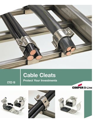
- 1. Cable Cleats Protect Your Investments CTCC-10
- 2. Introduction Protect your People Protect your Cables Protect your Systems Cooper B-Line Cable Cleats are designed to support and retain your cables within your cable tray system in everyday conditions. More importantly, they help prevent damage in short circuit conditions. Unfortunately, short circuits do happen, and when they do, they are destructive and dangerous. Cable Cleats are one of the first lines of defense to help protect your personnel, your cables and your cable tray systems. Properly restrained cables shown before Properly restrained cables shown after a a short circuit. short circuit. In the event of a short circuit, correctly installed cable cleats can restrain the cables within the tray, helping avoid cable breaks that can cause damage to the tray systems and injury to your personnel. Not only is this a prudent product to install, the National Electrical Code (NEC) requires adequate cable restraint in article 392.8 (D). “Parallel connected single conductor cables shall be securely bound in circuit groups to prevent excessive movement due to fault current magnetic forces.” NEC, Article 392.8 (D). The cleats in this catalog are covered under IEC Standard 61914. Cable cleats also help avoid downtime caused by short circuits. They help prevent the need for expensive repairs and downtime caused by short circuit damages. 2
- 3. Installation Photos Step by Step Installation 3
- 4. Cable Cleat Selection and Specification Step 1: Know Your Cables I What type of cable is being used? • Single or Multi-conductor I What is the outside diameter of the cable(s)? I What is the cable arrangement (single conductor cables only)? • Flat or Trefoil I If a ground wire will be installed within the cleat, you will need the ground wire outside diameter. Step 2: Know Your System I What is the available short circuit current (RMS or ip (peak))? I What type of Cooper B-Line cable tray is installed? Step 3: Select Your Cable Cleats I See Pages 6 & 7 Step 4: Select Your Mounting Bracket Mounting brackets are used to attach cable cleats to the rungs of the ladder type cable trays. Your tray type will determine the mounting bracket used. Cooper B-Line Tray Types Mounting Bracket Aluminum welded rung trays with standard rungs. Steel Series 2, 3, 4 or 5, trays with standard rungs 9SS6-CCB-C Fiberglass trays with standard rungs REDI-Rail™ Cable Tray 9SS6-CCB-D Steel trays with strut rungs 9SS6-CCB-B Aluminum trays with “Marine Rungs” Steel Series 1 trays with standard rungs 9SS6-CCB-A Use with rungs Use with rungs 9SS6-CCB-A 1” 9SS6-CCB-B 15/8” 1/2” 1” 11/2” 9SS6-CCB-C Use with rungs 9SS6-CCB-D Use with rungs 1” 1” 3/4” 11/2” 25/32” 1” 1” 11/2” 4
- 5. Cable Cleat Selection and Specification Step 5: Determine Cleat Spacing for Installation Your cable diameter is equal to the spacing between conductor centers shown below. Find your cable diameter at the top of the table and look down at the column below it. Find the value equal to or greater than the available short circuit for your system. Single Conductor Short Circuit Withstand Table Max. Cable Cleat Spacing Between Conductor Centers (mm) Spacing (A) 23 25 27 29 31 33 35 37 39 41 43 45 mm In. ip peak (kA) 225 9 179 187 194 203 209 216 220 229 234 240 246 250 300 12 155 163 168 174 181 187 192 198 203 209 214 215 450 18 128 133 137 144 148 152 157 161 165 170 174 178 600 24 110 115 119 124 128 132 135 139 143 148 150 153 675 27 104 108 113 117 121 124 128 132 135 139 143 147 900 36 89 93 97 102 104 108 110 115 117 121 124 127 Changes of Direction 0.3M A A A A A A r) max (linea ma M 0.3 (lin x r) ea M 0.3 x ma ear) 0.3M Trefoil Cables (lin max ) (linear IMPORTANT: Recommended Installation Procedures It is important that the cleats are installed properly to secure your cables: • It is not necessary for every cleat to be attached to the tray. Every other cleat ( ) must be attached to the tray system to mount cable in tray. Unattached cleats ( ) provide additional restraint to keep cables bundled. • The bend radius should be 8 to 12 times the cable diameter. • Cleats should always be installed at the beginning, middle and end of a bend ( ), and at no time should the distance between cleats on a bend be more than 0.3M center to center. Cooper B-Line Sales Engineers are available to assist you in selecting your cable cleats. Phone: (800) 851-7415 ext. 366 5
- 6. Trefoil Cable Cleats Trefoil Cable Cleat with LSF Pad 1. Cable Cleats are recommended for installations where the highest levels of short circuit withstand are required. 2. Cable Cleats have been short circuit current tested in accordance with BS EN 50368:2003 standard. 3. Cable Cleats are available for single and trefoil cable applications. 4. Cable Cleat LSF-pad incorporate an integral low smoke, low fume, zero halogen pad. 5. Hardware to attach cleat to rung attachment bracket is included with cleat. Bracket must be ordered separately. W 55mm H BS EN 50368:2003 (Cable Cleats for Electric Installations) Technical Specifications Classification Frame 50mm x 2mm Marine grade, Non-magnetic 316L Cleat Type Composite Closure Hardware Captive 316 Stainless Steel M8 or M10 (M12 available) bolt Resistance to 130 kA peak / 50 kA RMS and nylon-lock nut (Optional Hex Flange Lock Nut available) Electromechanical Force 600 mm spacing Integral Pad Low Smoke, Low Fume, Zero Halogen Lateral Load Test 3.439 kg average Tools Required Impact Wrench Axial Load Test Pass Operating Temperature Range -40°C to +60°C Mounting Bolt Provided with Cable Cleat Impact Resistance Very Heavy Needle Flame Test 30 seconds Cable Range (mm) Dimensions (mm) Cable Range (mm) Dimensions (mm) Part No. Min. Dia. Max. Dia. H W Part No. Min. Dia. Max. Dia. H W 9SS6-CCT1323 13 22 74 66 9SS6-CCT6167 61 67 132 147 9SS6-CCT2125 21 25 77 70 9SS6-CCT6369 63 69 136 150 9SS6-CCT2329 23 29 81 78 9SS6-CCT6571 65 71 140 153 9SS6-CCT2531 25 31 84 81 9SS6-CCT6773 67 73 143 156 9SS6-CCT2733 27 33 86 83 9SS6-CCT6975 69 75 147 160 9SS6-CCT2935 29 35 90 89 9SS6-CCT7177 71 77 151 163 9SS6-CCT3238 32 38 94 95 9SS6-CCT7379 73 79 154 166 9SS6-CCT3541 35 41.5 98 100 9SS6-CCT7581 75 81 158 169 9SS6-CCT3844 38 44.5 101 104 9SS6-CCT7783 77 83 161 173 9SS6-CCT4248 42 48 105 111 9SS6-CCT7985 79 85 164 176 9SS6-CCT4551 45 51 109 117 9SS6-CCT8187 81 87 169 179 9SS6-CCT4753 47 53 111 120 9SS6-CCT8389 83 89 173 182 9SS6-CCT4955 49 55 114 124 9SS6-CCT8896 88 96 181 192 9SS6-CCT5157 51 57 116 127 9SS6-CCT96103 96 103 190 201 9SS6-CCT5359 53 59 119 133 9SS6-CCT103111 103 111 199 204 9SS6-CCT5561 55 61 127 137 9SS6-CCT111119 111 119 208 213 9SS6-CCT5763 57 63 126 140 9SS6-CCT119128 119 128 217 221 9SS6-CCT5965 59 65 128 144 6
- 7. Single Cable Cleats Single Cable Cleat with LSF Pad 1. Cable Cleats are recommended for installations where the highest levels of short circuit withstand are required. 2. Cable Cleats have been short circuit current tested in accordance with BS EN 50368:2003 standard. 3. Cable Cleats are available for single and trefoil cable applications. 4. Cable Cleat LSF-pad incorporate an integral low smoke, low fume, zero halogen pad. 5. Hardware to attach cleat to rung attachment bracket is included with cleat. Bracket must be ordered separately. W 55mm H BS EN 50368:2003 (Cable Cleats for Electric Installations) Technical Specifications Classification Frame 50mm x 2mm Marine grade, Non-magnetic 316L Cleat Type Composite Closure Hardware Captive 316 Stainless Steel M8 or M10 (M12 available) bolt Resistance to 130 kA peak / 50 kA RMS and nylon-lock nut (Optional Hex Flange Lock Nut available) Electromechanical Force 600 mm spacing Integral Pad Low Smoke, Low Fume, Zero Halogen Lateral Load Test 3.439 kg average Tools Required Impact Wrench Axial Load Test Pass Operating Temperature Range -40°C to +60°C Mounting Bolt Provided with Cable Cleat Impact Resistance Very Heavy Needle Flame Test 30 seconds Cable Range (mm) Dimensions (mm) Cable Range (mm) Dimensions (mm) Part No. Min. Dia. Max. Dia. H W Part No. Min. Dia. Max. Dia. H W 9SS6-CCS2832 28 32 61 55 9SS6-CCS6266 62 66 88 89 9SS6-CCS3034 30 34 63 57 9SS6-CCS6468 64 68 90 91 9SS6-CCS3236 32 36 65 59 9SS6-CCS6670 66 70 91 93 9SS6-CCS3438 34 38 67 61 9SS6-CCS6872 68 72 93 95 9SS6-CCS3640 36 40 17 63 9SS6-CCS7074 70 74 95 97 9SS6-CCS3842 38 42 69 65 9SS6-CCS7276 72 76 97 99 9SS6-CCS4044 40 44 71 67 9SS6-CCS7478 74 78 99 101 9SS6-CCS4246 42 46 72 69 9SS6-CCS7680 76 80 101 103 9SS6-CCS4448 44 48 74 71 9SS6-CCS7682 76 82 103 105 9SS6-CCS4650 46 50 75 73 9SS6-CCS8084 80 84 105 107 9SS6-CCS4852 48 52 77 75 9SS6-CCS8286 82 86 107 109 9SS6-CCS5054 50 54 79 77 9SS6-CCS8488 84 88 109 111 9SS6-CCS5256 52 56 80 79 9SS6-CCS8690 86 90 110 113 9SS6-CCS5458 54 58 81 81 9SS6-CCS9094 90 94 116 120 9SS6-CCS5660 56 60 83 83 9SS6-CCS94118 94 118 135 137 9SS6-CCS5862 58 62 85 85 9SS6-CCS118130 118 130 141 143 9SS6-CCS6064 60 64 86 87 9SS6-CCS127150 127 150 162 165 7
- 8. Cooper B-Line Product Lines Strut Systems (Bolted Framing) Cable Tray Systems Electrical Enclosures Electronic Enclosures Metering Pipe Hangers & Support Systems Spring Steel Fasteners Cable Runway & Relay Racks (CommData) Meter Mounting & Distribution Equipment Safety Grating Anchors CTCC-10 Cooper B-Line 509 West Monroe Street Highland, IL 62249 Phone: 800-851-7415 Fax: 618-654-1917 www.cooperbline.com B - V O C AL • Contact Information • L Questions, Comments, Suggestions? ““ SM SM with Cooper B-Line” Voice Of the Customer...Actively Listening bvocal@cooperindustries.com Toll Free: 877-351-9450 SYSTEMS THAT MAKE SENSE Cooper Industries, Ltd. 600 Travis, Ste. 5800 Houston, TX 77002-1001 Phone: 713-209-8400 www.cooperindustries.com © 2010 Cooper B-Line, Inc. Printed in U.S.A. 2110