
Recommended
Recommended
More Related Content
More from Lau Marrine
Recently uploaded
Recently uploaded (20)
Dispersion and dispersion compensation in wdm system
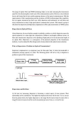
- 1. The usage of optical fiber and WDM technology helps us not only increasing the transmission speed but also decreasing the overall cost of the communication system. However, some technical factors still limited the bit rate and the spanning distance of the optical communication. With the improvement of fiber manufacturing and the invention of EDFA (erbium-doped fiber amplifier), the war against attenuation has been won, while dispersion and nonlinearity are still taken into main consideration in today’s high speed optical communication systems. This tutorial is going to talk about the dispersion and dispersion compensation in fiber optic transmission of WDM system. Dispersion in Optical Fibers About dispersion, the most familiar example is probably a rainbow, in which dispersion causes the spatial separation of a white light into components of different wavelengths (different colors). In fiber optic transmission, dispersion is the spreading of light pulse as its travels down the length of an optical fiber. Dispersion is a consequence of the physical properties of the transmission medium , it can be reduced by fiber design and is closely related to the optical source selection. Why is Dispersion a Problem in Optical Transmission? Dispersion compensation is an important issue for fiber-optic links. It limits the bandwidth or information carrying capacity of a fiber. The following picture will tell us why is dispersion a problem in optical fiber transmission. Dispersion and Bit Rate As bit rates are increasing, dispersion is becoming a critical aspect of most systems. Their relationship can be concluded as "the higher the dispersion the lower the bit rate". As we can see from the picture below, the higher dispersion is, the longer the bit interval must be used, while a longer bit interval means fewer bits can be transmitted per unit of time, ie. a lower bit rate.
- 2. Types of Dispersion in Optical Fibers In general, there are two different types of dispersion in optical fibers – intramodal and intermodal dispersion. Intramodal dispersion (chromatic dispersion) occurs in all types of fibers while intermodal dispersion (modal dispersion) occurs only in multimode fibers. Each type of dispersion mechanism leads to pulse spreading. Intramodal Dispersion (Chromatic Dispersion) Intramodal dispersion, or chromatic dispersion (CD) is caused by the fact that singlemode glass fibers transmit light of different wavelengths at different speeds. There are two factors that cause chromatic dispersion: material dispersion and waveguide dispersion. In general, both types of dispersion may be present, although they are not strictly additive. Their combination leads to signal degradation in optical fibers for telecommunications, because the varying delay in arrival time between different components of a signal "smears out" the signal in time. Chromatic Dispersion (CD) Material Dispersion – Material dispersion comes from a frequency-dependent response of a material to waves. For example, material dispersion leads to undesired chromatic aberration in a lens or the separation of colors in a prism. Material dispersion is not helpful in optical communications that it limits how much data can be sent, as the pulses will overlap and information will be lost. Waveguide Dispersion – Waveguide dispersion is caused by the wavelength dependence of the group velocity due to specific fiber geometry. Waveguide dispersion is important in waveguides with small effective mode areas. But for fibers with large mode areas, waveguide dispersion is normally negligible, and material dispersion is dominant. Intrermodal Dispersion (Modal Dispersion)
- 3. In a multimode fiber, different modes travel at different velocities, if a pulse is constituted from different modes then intermodal dispersion occurs. We call this type of dispersion as intermodal dispersion, or modal dispersion. Modal dispersion limits the bandwidth of multimode fibers. The more modes are, the greater the modal dispersion is. Typical bandwidth of a step index fiber may be as low as 10 MHz over 1 km. Modal dispersion may be considerably reduced, but never completely eliminated, by the use of a core having a graded refractive index profile. However, multimode graded-index fibers having bandwidths exceeding 3.5 GHz·km at 850 nm are now commonly manufactured for use in 10 Gbit/s data links. Polarization mode dispersion (PMD) – Polarization mode dispersion (PMD) is a special form of modal dispersion. This phenomenon describes a situation in which the electromagnetic wave components that make up an optical signal travel at differen speeds within the fiber. This causes a multipath interference at the receiver. PMD is difficult to predict and may possible vary with temperature and environment, the twisting of the cable as it was pulled, and even between production runs from the same manufacturer. In an ideal optical fiber, the core has a perfectly circular cross-section. In this case, the fundamental mode has two orthogonal polarizations (orientations of the electric field) that travel at the same speed. The signal that is transmitted over the fiber is randomly polarized, i.e. a random superposition of these two polarizations, but that would not matter in an ideal fiber because the two polarizations would propagate identically (are degenerate). However, there are random imperfections that break the circular symmetry in a realistic fiber where two different polarizations of light in a waveguide, which normally travel at the same speed, travel at different speeds due to random imperfections and asymmetries, causing random spreading of optical pulses. The symmetry-breaking random imperfections fall into several categories. First, there is geometric asymmetry, e.g. slightly elliptical cores. Second, the birefringences of the fiber, in which the refractive index itself depends on the polarization. Birefringence can be influenced by two factors, material birefringence and waveguide birefringence, similar to CD, but more complex. Waveguide birefringence is caused by geometrical variations in the fiber such as concentricity or ellipticity. Material birefringence is mainly caused by stress on the fiber. As the complexity of PMD, it usually needs to be compensated by the compensation device which uses a polarization controller to compensate for PMD in fibers.
- 4. Polarization Mode Dispersion (PMD) Dispersion Compensation Dispersion effects, as one of the main factors (other two factors are fiber attenuation and nonlinearity) which significantly limite the bit rate and the spanning distance of the optical communication, have to be taken into consideration. Dispersion compensation is often used in a more general sense of dispersion management, meaning the control the overall dispersion of some system. Nowadays, there are several important fiber technologies used to provide dispersion compensation, such as dispersion shifted fiber, non-zero dispersion shifted fiber, despersion compensating fiber and dispersion compensation module etc. Dispersion Shifted Fiber (DSF) The standard single-mode fiber deployed today is manufactured to optimize transmission at 1310 nm by effectively eliminating dispersion at that wavelength. The dispersion in the 1550 nm window far exceeds that for 1310 nm on standard fiber and hence is a limiting factor in single channel or DWDM systems operating in that window. Dispersion shifted fiber (DSF) is a type of single-mode optical fiber with a core-clad index profile tailored to shift the zero-dispersion wavelength from the natural 1300 nm in silica-glass fibers to the minimum-loss window at 1550 nm. It is best suited for application involving single channel transmission at 1550 nm taking advantage of allowing a communication system to possess both low dispersion and low attenuation. However, when used in wavelength division multiplexing systems, SDFs can suffer from four-wave mixing which causes intermodulation of the independent signals. As a result non- zero dispersion shifted fiber is often used. Non-zero Dispersion Shifted Fiber (NZDSF) Non-zero dispersion shifted fiber is a type of single-mode fiber which was designed to overcome the problems of dispersion-shifted fiber. Because of the small non-zero amount of dispersion that occurs in the 1550 nm window, four-wave mixing and other non-linear effects are minimized so that it can support WDM system. Dispersion Compensating Fiber (DCF) Dispersion compensating fiber (DCF) is a new specialty fiber that has a very high negative value of dispersion. It can actually reverse the effects of chromatic sidpersion suffered by 1550 nm signals that traverse standard single-mode fiber. It is used as a sort of inline pre- or post- equalization in form of a fiber spool of a particular length placed at one end of a link. However, DCF is not an optimal dispersion compensating solution for DWDM systems because it is effcient for only single wavelength. In addition, because DCF's high non-linear penalties, its optical power tolerance is limited. Dispersion Compensation Module (DCM)
- 5. Dispersion compensation module (DCM), as its name suggests, is a device which used for compensating the chromatic dispersion of a long span of transmission fiber. The Dispersion compensation modules (DCMs) are building blocks of the CWDM&DWDM optical transport system and serve at optical communication nodes to provide negative chromatic dispersion known as pulse spread phenomenon that limits the high-bit rateand maximal transmission distance of data along optical fibers. Typically, such a module provides a fixed amount of dispersion (e.g. normal dispersion in the 1.6-μm spectral region), although tunable dispersion modules are also available. A module can easily be inserted into a fiber-optic link because it has fiber connectors for the input and output. The insertion losses may be compensated with a fiber amplifier, e.g. an EDFA in a 1.5- μm telecom system. A dispersion compensation module is often placed between two fiber amplifiers. Due to its high performance, DCMs are now widely used in WDM systems. In addition, there are some technologies which are able to provide channelized dispersion management. For example, to correct dispersion at different wavelength (different channel in DWDM system) and provide continuous flexibility to accommodate network change and upgrades (eg. migrating from 8 to 16 channels).
- 6. Dispersion compensation module (DCM), as its name suggests, is a device which used for compensating the chromatic dispersion of a long span of transmission fiber. The Dispersion compensation modules (DCMs) are building blocks of the CWDM&DWDM optical transport system and serve at optical communication nodes to provide negative chromatic dispersion known as pulse spread phenomenon that limits the high-bit rateand maximal transmission distance of data along optical fibers. Typically, such a module provides a fixed amount of dispersion (e.g. normal dispersion in the 1.6-μm spectral region), although tunable dispersion modules are also available. A module can easily be inserted into a fiber-optic link because it has fiber connectors for the input and output. The insertion losses may be compensated with a fiber amplifier, e.g. an EDFA in a 1.5- μm telecom system. A dispersion compensation module is often placed between two fiber amplifiers. Due to its high performance, DCMs are now widely used in WDM systems. In addition, there are some technologies which are able to provide channelized dispersion management. For example, to correct dispersion at different wavelength (different channel in DWDM system) and provide continuous flexibility to accommodate network change and upgrades (eg. migrating from 8 to 16 channels).