IRJET- Design and Implementation of Solar Charge Controller
Digital Implementation of Paralleling DC_DC conv
1. DA148 1
Abstract— This paper describes implementation of
digitally controlled current sharing in multiple power modules to
be used in high current requirement applications. This leads to
better system performance and system cost reduction.
The Digital Load share controller is developed using low cost
PIC16F876A µC with appropriate analog interface. The
performance of the Digital Load share controller is presented in
this paper along with Analog Load share controller UCC29002.
Index Terms— Analog Load Share Controller, Digital Load share
controller, Isolated buck DC-DC converter, paralleled power
modules.
I. INTRODUCTION
wide range of mission critical applications such as
Satellites, telecommunication, servers, etc., requires
either or both (n+1) redundancy and high load current
requirement. In order to satisfy the above needs we need to
provide Multiple Paralleled Power modules. But whenever the
converter modules are in parallel, one power module will take
the full load and the other module becomes idle. In order to
overcome this problem the only solution is current sharing
among the parallel power modules.
The current sharing equalizes the load current and thermal
stresses among paralleled power modules which lead to
improvement in overall system performance. The current
sharing also provides an improvement in terms of electrical
component reliability; for example, Mean Time between
Failure (MTBF) roughly doubles with every 10°C decrease in
operating temperature. Enforcing proper load sharing can also
result in using power supplies with lower nominal ratings
because of the reduced current in each. This technique, in turn,
can translate into an overall lower system cost.
There are several typical Current sharing methods, such as -
Automatic Master/ Slave Architecture
Droop Architecture
Democratic Architecture
Current mode control
Master/ slave Architecture
Dhananjay P, M.TECH – Power Electronics, 4th Semester, The Oxford
College of Engineering, Bangalore, dhananjay474@gmail.com, Phone no:
9480011359.
Jayakumar, M.TECH, Assistant Professor, EEE Dept, The Oxford College
of Engineering, Bangalore, njktry@yahoo.co.in.
Among various methods specified Automatic Master/
Slave architecture is more efficient and hence implemented in
this work.
II. WORKING OF PIC16F876A BASED DIGITAL LOAD SHARE
CONTROLLER:
The basic working of Digital Load share control card is
based on Automatic master/ slave architecture. Where the
power module carrying highest current will be the master and
the remaining modules becomes the slave. The slave power
module adjusts its regulated output voltage in terms of mV
according to command received from master module until
balanced current sharing occurs.
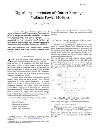
The Fig 2.1 shows the block diagram of two paralleled
24V/15A DC-DC converter along with two PIC16F876A µC
based Digital Load share controller connected at the load side.
For reasons of simplicity, only two converters are paralleled in
this work. The functional blocks of PIC16F876A µC based
Digital load share control
Fig 2.1 Digital load share control card connected to
multiple 24V/15A DC – DC converters
card is shown in the Fig 2.2 and its working are as follows:
A. Current Sense resistor (Rsense):
The Current sense resistor connected in positive output
rail of the DC/DC converter is of value 2mΩ. Rsense resistor
provides a maximum of 30mV, as an input to the Differential
Current sense amplifier at full load of 15A. The advantage of
Rsense resistor is, power dissipation is very less of 0.45W at
full load.
Digital Implementation of Current Sharing in
Multiple Power Modules
A. Dhananjay P and B. Jayakumar
A
2. DA148 2
B. Differential Current Sense Amplifier:
Its used to measure voltage across current sense resistor
(Rsense) which will be in terms of mV. The gain of the
Differential currrent sense amplifier is 100. Hence, the output
of the differential amplifier will be,
Vcso = Gain × (Vin+ - Vin-) 2.1
The maximum output of current sense amplifier is 3V at full
load of 15A. The current sense amplifiers Noise roll off is
designed for 3.5Hz.
Fig 2.2 Functional Blocks of Digital Load Share
Control Card.
C. Load Share Unity Gain Amplifier:
It’s a unity gain buffer amplifier to provide isolation
between the Load share bus voltage and the output of Current
sense amplifier. The amplifiers feedback consists of diode
which is used to select the particular power module as ‘master’
and remaining modules as ‘slave’.
D. Buffer:
It’s a unity gain buffer, which is used to ensure that the
Load Share bus is not loaded by the internal impedance of the
Digital control card and to provide the Load Share bus voltage
to one of the analog pin of µC.
E. Load Share Bus:
The Load share bus is used to carry the Master modules
current sense voltage (Vcso) to the Buffer of the slave Power
modules digital control card.
F. Programmable Current Sink:
The output voltage of the R-C filter is used to adjust the
output voltage of the slave power module to balance the load
current. This is done by the adjust amplifier and its companion
NPN transistor. The adjust amplifier provides signal
conditioning for the error signal and its output drives an NPN
transistor which is configured as a programmable current sink.
A resistor from its emitter to ground and the error voltage
defines the current, IADJ, which flows through the ADJ pin of
the digital Load–share controller and the positive output
terminal. The IADJ current causes a voltage drop across the
resistor which requires the power supply to increase its output
voltage. The resulting higher power supply output voltage
increases the output current of that particular module until the
output current levels equal out among the units. At that point
load sharing has been established.
G. Algorithm:
The following operations have been performed in the program
for current sharing in multiple power modules.
1. The analog signal of the differential current sense
amplifier output and Load share bus voltage has been
converted to digital form using the inbuilt “Analog to digital
converter”
2. Comparison of the “Load share bus digital value” and
“Current sense amplifier digital value” is done. Here, the
Output may be…
(I) If “Load share bus digital value” is greater than the
“Current sense amplifier digital value” by 100mV, the µC
increments the error voltage from zero.
(II) If the “current sense amplifier digital value” becomes
greater than or equal to “Load share bus digital value” by
100mV, the adjust voltage stops incrementing and retains the
previous value. Hence during this condition balanced current
sharing is achieved.
(III)If the “Load share bus digital value” becomes less
than or equal to the “Current sense amplifier digital value” by
10mV then the error voltage starts decreasing and continues to
decrease until the above condition becomes false or error
voltage reaches to zero. This condition occurs during false
operation of the system i.e. when the load share bus shorts with
the ground or supply or when the other Power module Turn –
off.
In order to provide the stability to the digital controller
we have provided a “Hysteresis gap” of 90mV between the
increment and decrement conditions. After performing one of
the above three conditions, the samples of Current sense
amplifier output value and the Load share bus value are again
obtained and checked for any of the three conditions discussed
above.
The detailed working of the µC is shown in the fig
2.3.The averages of 16 samples of individual current sense
amplifier value and load share bus value are calculated
separately and further used for computation purposes. This is
to eliminate the effect of noise on the analog input or wrong
conversion.
In order to convert the Digital adjust voltage value to
DC form, we use the combination of PWM generator and RC
filter instead of DAC, mainly to reduce the system cost.
System configuration required in order to use the Digital
Load share control card is – “Power module should have
Remote sense capability or the Power module should have
adjust input or both”.
III. BRIEF REVIEW OF CONVENTIONAL ANALOG LOAD SHARE
CONTROLLER:
3. DA148 3
Among various available Analog Load share control IC’s
in market we have chosen UCC29002 IC made by Texas
instrument. The Analog control cards are designed using large
number of on-chip op-amp’s and transistors to establish
Automatic Master/Slave architecture as shown in Fig 3.1. Here
the UCC29002 is capable of current sharing with 1% current
share error. It is also capable of current sharing only for range
of output voltage 4.5V to 35V. The IC is capable of fault
analysis and protection i.e. when the load share bus is shorted
to ground or supply. The UCC29002 load share control IC
requires minimum external components as shown in fig 3.2.
IV. ADVANTAGES OF DIGITAL LOAD SHARE CONTROL CARD:
A complex control algorithm is difficult to implement with
analog hardware components but can be easily implemental
in firmware.
Soft starting, slope compensation, interleaving, and fault
protection can also be easily implemented without any
external components.
Modifying the control methodology for different field
applications requires only software revision, and does not
require hardware modification.
The fan out can be increased.
Accurate current sharing of less than 1% current share error
at full load may be achieved.
V. EXPERIMENTAL SETUP:
The specifications of the Isolated buck DC – DC converters
used in this prototype are shown in Table 5.1. The Digital load
share controller designed is evaluated by placing Digital
control card in one power module and the UCC29002 based
Analog control card in another power module as shown in the
Fig5.1. Before evaluating the performance of the Digital Load
share control card, we set one power module as the Master and
the other as the slave. In the Fig5.2 the power module on the
right side is the master, taking the full load and the power
module on the left side is the slave, taking no load. The master
module Output voltage is greater than the slave power module
by 0.1V. When the digital control card power supply of +12V,
±5V is made on, the current sharing take place and finally the
balanced current sharing is achieved as shown in Fig 5.3.
Fig2.3: Flow Chart of working of PIC16F876A in Digital Load Share control Card.
Since Load share bus voltage is greater than the current sense
amplifier output voltage in the slave module. The
microcontroller makes error voltage to increase in terms of
20mV. Hence there will be a voltage drop at the resistor
4. DA148 4
present at the emitter side of the programmable current sink
which makes the output voltage of the slave module to rise by
driving the current.
Fig 3.1: Functional Blocks of UCC29002 Analog Load share control IC
Fig 3.2: Typical UCC29002 Load share controller connection in between the
power supply and the common power bus.
Fig 5.1: Proposed Parallel DC – DC converter with Digital Load share control
card.
Table 5.1: Specifications of Isolated DC-DC converter.
The output current of the slave module increases until uniform
current sharing occurs in both the module. When the balanced
current sharing occurs the Load share bus amplifier output
voltage will be almost equal to current sense amplifier output
and under this condition output voltage on both the power
module will be of 24.2V.
Fig 5.2: The paralleled Power modules output Voltage and current display
before current sharing.
Fig 5.3: Balanced current sharing of two paralleled 24V/15A DC – DC
converters.
VI. EXPERIMENTAL RESULTS AND DISCUSSIONS:
The test results is taken for both PIC16F876A µC based and
UCC29002 based load share controller as shown in the table
6.1 and 6.2. The digital load share controller exhibits efficient
operation under wide power ranges and it’s capable of
generating 5V as an
Table 6.1: Test results of UCC29002 based Load share control of two
Paralleled DC-DC converter modules
Table 6.1: Test results of PIC16F876A µC based Load share control of two
Paralleled DC-DC converter modules.
Input to the programmable current sink and in this work the
maximum voltage input given to the programmable current
sink by µC is 2V. The analog load share controller UCC29002
is capable of generating only 3V as error voltage to
programmable current sink used in the IC. When the current
sense amplifier output voltage is greater than 5V we can just
place the potential divider at the input of the µC, hence it’s
capable for higher current application greater than 50A. The
Digital current share control card is capable of adjusting the
voltage of the slave module for large voltage difference
between the slave and master module of 0.5V accurately. But
5. DA148 5
Analog current share controller UCC29002 is capable of
adjusting the voltage for small voltage difference of 0.2V
between the slave and master module.
VII. CONCLUSION:
From the above test results we can say that the low cost digital
load share control card can replace the analog load share
control card with accuracy in its current sharing and various
advantages of it compared to analog load share controller as
discussed earlier. The usage of these digital load share
controller as proven advantageous over some of the previous
Digital controller because of its parallel processing capability
and due to its hybrid quality; of using both digital and analog
components. By choosing Hybrid load share controller we
have reduced the burden on the µC and maintained sufficient
computational speed and performance without opting for High
end processors such as DSP.
VIII. ACKNOWLEDGMENT
The current work was carried out at M/S Chirra Electronics
Power labs Pvt Ltd, Bangalore. We wish to acknowledge their
support and guidance throughout the tenure of this work.
IX. REFERENCES
[1]T.S.Anandhit, S.P.Natarajan and T.Anitha, “UC3907 ASIC and
TMS320F2407A DSP based Control of Paralleled Buck DC-DC
Converters”, Indicon 2005 Conference, Chennai, India, 11- 13 Dec. 2005
[2] Siew-Chong Tan, Yuk-Ming Lai and Kevin Yan-Chun Wong, “An
Alternative configuration for Digitally controlled parallel connected DC-
DC Power Converters”, ECTI transactions on Electrical eng, electronics
and communications vol.4, no.1 February 2006
[3]Texas Instrument, “UCC29002 Load Share Controller” , 2007
[4] GUO Guoyong and SHI Bingxue, “Design of multi-phase dc-dc converter
with master-slave current sharing control”, IEEE, 2002.