SlideShare a Scribd company logo
1 of 16
Download to read offline
2009
          HNC CAD/CAM
SOFTWARE APPLICATIONS ASSINGMENT
           “TURNING”


                        David Antuna
                        GSD
                        11/25/2009
HNC CAD/CAM                                      SOFTWARE APPLICATIONS                                               DAVID ANTUNA


Table of Contents:


Summary: ................................................................................................................................... 3


1.     Introduction. ....................................................................................................................... 4


2.     Feed rate. ............................................................................................................................ 5


3.     Spindle speed...................................................................................................................... 6


4.     Depth of Cut. ...................................................................................................................... 6


5.     Cutting speed. ..................................................................................................................... 7

     5.1      Work Piece Drawing. . ................................................................................................. 9
     5.2      Calculation of Optimum Cutting Speeds. ..................................................................... 10

6.     Calculation of Power Required for Machining Operations. ............................................. 12


7.     Conclusion: ....................................................................................................................... 14


8.     References: ....................................................................................................................... 15


9.     Report Definitions: ........................................................................................................... 16


                                                                      2
HNC CAD/CAM                     SOFTWARE APPLICATIONS                        DAVID ANTUNA


Summary:

The intention of this report is to briefly, explain some of the machining operations that are
involved in the process of TURNING, these are: Cutting Speed, Depth of Cut, Feed Rate and
Spindle Speed.

Also demonstrated will be the mathematical calculations involved in the same process,
using various equations.


                                              3
HNC CAD/CAM                      SOFTWARE APPLICATIONS                         DAVID ANTUNA


1. Introduction:
The phrase speeds and feeds (or feeds and speeds) refers to two separate velocities in
machine tool practice, cutting speed and feed rate. (Brown & Sharpe, Automatic Screw Machine
Hand book :) They are often considered as a pair because of their combined effect on the
cutting process. Each, however, can also be considered and analyzed in its own. Cutting
speed is the speed difference between the cutting tool and the surface of the work piece it
is operating on, It is expressed in units of distance along the work piece surface per time.
Feed rate is the velocity at which the cutter is fed, that is, advanced against the work piece.
It is expressed in units of distance per revolution for turning and boring (typically inches per
revolution (ipr) or millimetres per revolution). It can be expressed thus for milling also, but it
is often expressed in units of distance per time for milling (typically inches per minute [ipm]
or millimetres per minute). Cutting speed and feed rate together determine the material
removal rate, which is the volume of work piece material (metal, wood, plastic, etc.) that
can be removed per time unit.

If variables such as cutter geometry and the rigidity of the machine tool and its tooling setup
could be ideally maximized (and reduced to negligible constants), then the amount of power
(that is, kilowatts or horsepower) available to the spindle would determine the maximum
speeds and feeds possible for any given work piece material and cutter material. Of course,
in reality those other variables are dynamic and not negligible; but there is still a correlation
between power available and feeds and speeds employed.


                                                4
HNC CAD/CAM                       SOFTWARE APPLICATIONS                         DAVID ANTUNA


2. Feed rate.
Feed rate is the velocity at which the cutter is fed, (Brown & Sharpe, Automatic Screw Machine Hand
book :) that is, advanced against the work piece. It is expressed in units of distance per
revolution for turning and boring (typically inches per revolution [ipr] or millimeters per
revolution). It can be expressed thus for milling also, but it is often expressed in units of
distance per time for milling (typically inches per minute [ipm] or millimeters per minute),
with considerations of how many teeth (or flutes) the cutter has then determining what that
means for each tooth.

Feed rate is dependent on the:

      Surface finish desired.
      Power available at the spindle (to prevent stalling of the cutter or work piece).
      Rigidity of the machine and tooling setup (ability to withstand vibration or chatter).
      Strength of the work piece (high feed rates will collapse thin wall tubing)
      Characteristics of the material being cut, chip flow depends on material type and
       feed rate. The ideal chip shape is small and breaks free early, carrying heat away
       from the tool and work.

When deciding what feed rate to use for a certain cutting operation, the calculation is fairly
straightforward for single-point cutting tools, because all of the cutting work is done at one
point (done by "one tooth", as it were). With a milling machine or jointer, where multi-
tipped/multi-fluted cutting tools are involved, then the desirable feed rate becomes
dependent on the number of teeth on the cutter, as well as the desired amount of material
per tooth to cut (expressed as chip load). The greater the number of cutting edges, the
higher the feed rate permissible: for a cutting edge to work efficiently it must remove
sufficient material to cut rather than rub; it also must do its fair share of work.


                                                5
HNC CAD/CAM                       SOFTWARE APPLICATIONS                          DAVID ANTUNA


3. Spindle Speed.
The spindle speed is the rotational frequency of the spindle of the machine, (Brown & Sharpe,
Automatic Screw Machine Hand book :) measured in revolutions per minute (RPM). The preferred
speed is determined by working backward from the desired surface speed (sfm or m/min)
and incorporating the diameter (of work piece or cutter).

The spindle may hold the:

      Drill bit in a drill
      Milling cutter in a milling machine
      Router bit in a wood router
      Shaper cutter or knife in a wood shaper or spindle moulder
      Grinding wheel on a grinding machine.
      Or it may hold the chuck which then holds the work piece in a lathe. In these cases
       the tool bit remains stationery although exceptions may be found such as in thread
       milling.


4. Depth of Cut:

The easiest cutting parameter to adjust is the depth of cut. (Fox Valle Technical College. Machine
Shop) Doubling the depth of cut in a turning operation will double the metal removal rate
without any increase in cutting temperature. The horsepower consumed will virtually
double, but there will be no reduction in tool life (specific wear per inch of cutting edge
length) assuming the cutting edge can withstand the added tangential cutting force.
However, it is not always possible to increase the depth of cut to gain additional
productivity, since there might not be any remaining material to remove.


                                                 6
HNC CAD/CAM                      SOFTWARE APPLICATIONS                          DAVID ANTUNA


5. Cutting Speed:
Cutting speed may be defined as the rate (or speed) that the material moves past the
cutting edge of the tool, (Brown & Sharpe, Cam & Tool Design: Surface Cutting Speeds Chart, p. 5)
irrespective of the machining operation used — the surface speed. A cutting speed for mild
steel, of 100 ft/min (or approx 30 meters/min) is the same whether it is the speed of the
(stationary) cutter passing over the (moving) work piece, such as in a turning operation, or
the speed of the (stationary) work piece moving past a (rotating) cutter, such as in a milling
operation. What will affect the value of this surface speed for mild steel, is the cutting
conditions:

For a given material there will be an optimum cutting speed for a certain set of machining
conditions, and from this speed the spindle speed (RPM) can be calculated. Factors affecting
the calculation of cutting speed are:

      The material being machined (steel, brass, tool steel, plastic, wood) (see table below)
      The material the cutter is made from (Carbon steel, High speed steel (HSS), carbide,
       ceramics)
      The economical life of the cutter (the cost to regrind or purchase new, compared to
       the quantity of parts produced).

Cutting speeds are calculated on the assumption that optimum cutting conditions exist,
these include:

      Metal removal rate (finishing cuts that remove a small amount of material may be
       run at increased speeds)
      Full and constant flow of cutting fluid (adequate cooling and chip flushing)
      Rigidity of the machine and tooling setup (reduction in vibration or chatter)
      Continuity of cut (as compared to an interrupted cut, such as machining square
       section material in a lathe)
      Condition of material (mill scale, hard spots due to white cast iron forming in
       castings)


                                                7
HNC CAD/CAM                    SOFTWARE APPLICATIONS                      DAVID ANTUNA


The cutting Speed is given as a set of constants that are available from the material
manufacturer or supplier, the most common materials are available in reference books, or
charts but will always be subject to adjustment depending on the cutting conditions. The
following table gives the cutting speeds for a selection of common materials under one set
of conditions. The conditions are a tool life of 1 hour, dry cutting (no coolant) and at
medium feeds so they may appear to be incorrect depending on circumstances. These
cutting speeds may change if, for instance, adequate coolant is available or an improved
grade of HSS is used (such as one that includes cobalt).


     Cutting speeds for various materials (Based on a plain High Speed Steel cutter)
Material type                        meters per min                feet per min
Steel (tough)                        15 - 18                       50 - 60
Mild steel                           30-38                         100-125
Cast iron (medium)                   18-24                         60-80
Bronzes                              24-45                         80-150
Brass (soft)                         45-60                         150-200
Aluminium                            75-105                        250-350
Table 1 Cutting Speeds Parameters.


                                             8
HNC CAD/CAM                      SOFTWARE APPLICATIONS                         DAVID ANTUNA


   5.1 Work piece Drawing:
The following diagram shows an example of work piece that could be machine/turn in a lathe.

This drawing was made using the design software AUTO CAD.


Table 2 Process of Turning


                                                9
HNC CAD/CAM                    SOFTWARE APPLICATIONS                                     DAVID ANTUNA


5.2 Calculation of Optimum Cutting Speeds:


The following are the results from the calculations made for the cuttings speeds displayed
below.

The calculations where made using the following equation:

                                         ������������������������                       ������������������������
                        RPM =                                 =
                                 ������������������������������������������������������������������������������       ������������������������������������������������������������


             CALCULATION OF OPTIMUM CUTTING SPEEDS FOR HARDENED STEEL

     DIAMETER OF SHAFT IN MM                        FEED RATE IN MM/Min.                      RPM
               20                                          15000                          238.7324146
               40                                          15000                          119.3662073
               60                                          15000                          79.57747155


                 CALCULATION OF OPTIMUM CUTTING SPEEDS FOR BRONZE

     DIAMETER OF SHAFT IN MM                        FEED RATE IN MM/Min.                      RPM
               20                                          24000                          381.9718634
               40                                          24000                          190.9859317
               60                                          24000                          127.3239545

                 CALCULATION OF OPTIMUM CUTTING SPEEDS FOR BRASS

     DIAMETER OF SHAFT IN MM                        FEED RATE IN MM/Min.                      RPM
               20                                          45000                          716.1972439
               40                                          45000                          358.098622
               60                                          45000                          238.7324146

               CALCULATION OF OPTIMUM CUTTING SPEEDS FOR ALUMINIUM

     DIAMETER OF SHAFT IN MM                        FEED RATE IN MM/Min.                      RPM
               20                                          75000                          1193.662073
               40                                          75000                          596.8310366
               60                                          75000                          397.8873577


                                                 10
HNC CAD/CAM                    SOFTWARE APPLICATIONS                        DAVID ANTUNA


This scatter graph displays the optimum cutting speeds for the various metals shown in this
report.


                                CUTTING SPEEDS
     1400


     1200


                                                                             HARDENED
                                                                             STEEL
     1000

                                                                             BRONZE


     800
                                                                             BRASS
 R
 P
 M
     600                                                                     ALUMINIUM


     400


     200


        0
            0     10      20          30    40       50       60       70

                          DIAMETER OF SHAFT IN MM


Table 3 Cutting Speed Calculations.


                                            11
HNC CAD/CAM                         SOFTWARE APPLICATIONS                                       DAVID ANTUNA


6. Calculation of Power Required for Machining Operations.

The table below displays the results of the calculations of the power required to turn Ø100
mm bar at the various speeds.

The following equation was used:

                                 ������������������������������ ������ ������������������������������������������ ������ ������������������������������������������������������(������������������ ������������������ ������������������)
           Power (W) =
                                                                  ������������


         CALCULATION OF POWER REQUIRED FOR CUTTING OPERATIONS

                                                                SPEED IN
  DIM. OF SHAFT IN MM        RADIUS OF SHAFT IN MM              REV/MIN             CUTTING FORCE IN (N)         POWER
          100                          0.05                         40                         350               73.30
          100                          0.05                         80                         350               146.61
          100                          0.05                        160                         350               293.22
          100                          0.05                        320                         350               586.43


                    POWER REQUIRED FOR MACHINING
                             OPERATIONS
       700.00
       600.00
   P
       500.00
   O                                                                                                 Power
       400.00
   W                                                                                                 steel
       300.00
   E
       200.00                                                                                        Bronze
   R
       100.00                                                                                        Brass
         0.00
                                                                                                     Aluminium
                0       50       100       150        200       250        300        350
                                       SPEED IN REV PER MIN.


Table 4 Power Required for Machining Operation


                                                      12
HNC CAD/CAM                      SOFTWARE APPLICATIONS                         DAVID ANTUNA


As we can see from the table above, the higher the revolution per minute the higher the
power is required to cut/machine an object, in this case a solid shaft of 100mm of diameter.

These actions also influences on the tool life, the reason is simple, as it is stated above, the
higher the revs/min the higher the power is required therefore the harder the tool has to
work.

In this report we have taken four kinds of metal, hardened steel, bronze, brass and
aluminium, so if bronze is taking as a example we can deduct that it will be harder to
machine, therefore it will need a low set of feed and speed and doing so it will required just
the correct amount of power to do the job.

A company that it’s main activity is machining parts, i.e. A nuts and bolts factory, will
depend in it’s ability to maximize the use of the cutting tools, therefore all the machinery
must work with the optimum set up (cutting speed, feed rate & depth of cut) to make the
most of every cutting tool.


                                               13
HNC CAD/CAM                     SOFTWARE APPLICATIONS                        DAVID ANTUNA


7. Conclusion:

In this report we have learned that in the process of cutting/machining in the context of
TURNING, there is a very fine balance between setting up the optimum cutting speed, feed
rate and depth of cut. This balance if is apply correctly it should create the maximum level of
working condition to obtain the best results from the job in hand.


                                             14
HNC CAD/CAM                          SOFTWARE APPLICATIONS                               DAVID ANTUNA


8. References:

World Wide          In-Text         Reference                              End Note
  Web              Example         List Example
Document on      The phrase            Brown &        Electronic Source
WWW              speeds and             Sharpe,       Wikipedia the free Encyclopedia.
                 feeds refers to      Automatic       26 Nov. 2009 (last revision)
                 two separate       Screw Machine
                 velocities in        Handbook:       http://en.wikipedia.org/wiki/Feed_rate
                 machine tool         Brown and
                 practice.          Sharpe Speeds
                                      and Feeds
                                    Chart, p. 222 &
                                          223
Document on      Feed rate is      Brown &            Electronic Source
WWW              the velocity at   Sharpe,            Wikipedia the free Encyclopedia.
                 which the         Automatic          26 Nov. 2009 (last revision)
                 cutter is fed.    Screw Machine
                                   Handbook:          http://en.wikipedia.org/wiki/Feed_rate


Document on      The spindle       Brown &            Electronic Source
WWW              speed is the      Sharpe,            Wikipedia the free Encyclopedia.
                 rotational        Automatic          26 Nov. 2009 (last revision)
                 frequency of      Screw Machine.     http://en.wikipedia.org/wiki/Spindle_speed
                 the spindle of
                 the machine.
Document on      The easiest       Fox Valle          Electronic Source
WWW              cutting           Technical          Put on Fox Valle Technical College in year 2000.
                 parameter to      College.           http://its.fvtc.edu/machshop4/Carbcut/Cutspeeds.htm
                 adjust is the     Machine Shop
                 depth of cut.     web pages.
Document on      Cutting speed     Brown &            Electronic Source
WWW              may be            Sharpe, Cam &      Wikipedia the free Encyclopedia.
                 defined as the    Tool Design:       26 Nov. 2009 (last revision)
                 rate (or speed)   Surface Cutting    http://en.wikipedia.org/wiki/Cutting_speed
                 that the          Speeds Chart, p.
                 material          5
                 moves past
                 the cutting
                 edge of the
                 tool.
Picture on the   The term          Copyright ©        Electronic Source
                                   2009 eFunda,
WWW              "facing" is       Inc.
                                                      Efunda TURNING
                 used to
                 describe                             http://www.efunda.com/processes/machining/turn.cfm
                 removal of
                 material from
                 the flat end of
                 a cylindrical
                 part.


                                                      15
HNC CAD/CAM                      SOFTWARE APPLICATIONS                         DAVID ANTUNA


9. Report Definitions:

The following is a list of definitions of the structural points that composed this report.

       Title Page: The Title page is the very first page of a report and can be composed form
       only text with the information about the course to a very elaborate visual page with
       colour and pictures about the subject in the report.

       Summary: The summary is a shorten version of the subject that has been said or
       written in a report or a discussion, containing only the main points.


       Table of Contents: This is the page where the content of a report is listed, including
       pictures, graphs, tables and external work, all it is shown with its page number.

       Introduction: The introduction is the section at the beginning of a report that
       summarizes what it is about, also gives the reader the basic facts or skills in a field.


       Body/Discussions: This is the main part of a report, when the subject in the report is
       presented with all its facts, all the research done and all the support work. i.e.
       graphs, tables, photographs etc...

       Conclusions: This is the part in a report where after looking in to all the discussions
       within the report it brings it in to a formal closure.


       References: The reference states to the reader in a list or table of all the information
       use to help to complete the report from authors other that the creator of the report.

       Appendices: This part in the document is where is set all the separate material that
       are part of the report but it has not been made by the creator of the same.

       Acknowledgments: In this section of the report the author thanks those who have
       help in the making of the report.


                                               16

More Related Content

What's hot

Theory of-metal-cutting
Theory of-metal-cuttingTheory of-metal-cutting
Theory of-metal-cuttingGaurav Gunjan
 
International Journal of Engineering Research and Development
International Journal of Engineering Research and DevelopmentInternational Journal of Engineering Research and Development
International Journal of Engineering Research and DevelopmentIJERD Editor
 
Metalcutting 140822084807-phpapp01
Metalcutting 140822084807-phpapp01Metalcutting 140822084807-phpapp01
Metalcutting 140822084807-phpapp01manojkumarg1990
 
heat in metal cutting
heat in metal cuttingheat in metal cutting
heat in metal cuttingRania Atia
 
Economics of metal cutting operations
Economics of metal cutting operationsEconomics of metal cutting operations
Economics of metal cutting operationsDarshan Panchal
 
Theory of metal cutting-module II
Theory of metal cutting-module IITheory of metal cutting-module II
Theory of metal cutting-module IIDr. Rejeesh C R
 
High speed machining imts 2012
High speed machining imts 2012High speed machining imts 2012
High speed machining imts 2012Maggie Smith
 
Theory of metal cutting - Part 2
Theory of metal cutting - Part 2Theory of metal cutting - Part 2
Theory of metal cutting - Part 2Arun Senthil Kumar
 
Metal cutting basics min
Metal cutting basics minMetal cutting basics min
Metal cutting basics minNagarajpatil42
 
Optimization of snap design parameters to avoid bursting and ring formation o...
Optimization of snap design parameters to avoid bursting and ring formation o...Optimization of snap design parameters to avoid bursting and ring formation o...
Optimization of snap design parameters to avoid bursting and ring formation o...IAEME Publication
 
MULTI OBJECTIVE OPTIMIZATION OF CUTTING PARAMETERS IN TURNING OPERATION OF ST...
MULTI OBJECTIVE OPTIMIZATION OF CUTTING PARAMETERS IN TURNING OPERATION OF ST...MULTI OBJECTIVE OPTIMIZATION OF CUTTING PARAMETERS IN TURNING OPERATION OF ST...
MULTI OBJECTIVE OPTIMIZATION OF CUTTING PARAMETERS IN TURNING OPERATION OF ST...IAEME Publication
 
An Investigation on Surface Roughness of A356 Aluminium Alloy in Turning Proc...
An Investigation on Surface Roughness of A356 Aluminium Alloy in Turning Proc...An Investigation on Surface Roughness of A356 Aluminium Alloy in Turning Proc...
An Investigation on Surface Roughness of A356 Aluminium Alloy in Turning Proc...IRJET Journal
 

What's hot (19)

Theory of-metal-cutting
Theory of-metal-cuttingTheory of-metal-cutting
Theory of-metal-cutting
 
Theory of metal cutting
Theory of metal cuttingTheory of metal cutting
Theory of metal cutting
 
Ll3619651969
Ll3619651969Ll3619651969
Ll3619651969
 
International Journal of Engineering Research and Development
International Journal of Engineering Research and DevelopmentInternational Journal of Engineering Research and Development
International Journal of Engineering Research and Development
 
Metalcutting 140822084807-phpapp01
Metalcutting 140822084807-phpapp01Metalcutting 140822084807-phpapp01
Metalcutting 140822084807-phpapp01
 
METAL MACHINING
METAL MACHININGMETAL MACHINING
METAL MACHINING
 
heat in metal cutting
heat in metal cuttingheat in metal cutting
heat in metal cutting
 
Heat in metal cutting
Heat in metal cuttingHeat in metal cutting
Heat in metal cutting
 
Chapter7b machining turning(1)
Chapter7b machining turning(1)Chapter7b machining turning(1)
Chapter7b machining turning(1)
 
Economics of metal cutting operations
Economics of metal cutting operationsEconomics of metal cutting operations
Economics of metal cutting operations
 
Theory of metal cutting-module II
Theory of metal cutting-module IITheory of metal cutting-module II
Theory of metal cutting-module II
 
High speed machining imts 2012
High speed machining imts 2012High speed machining imts 2012
High speed machining imts 2012
 
Theory of metal cutting - Part 2
Theory of metal cutting - Part 2Theory of metal cutting - Part 2
Theory of metal cutting - Part 2
 
Production Engg. Theory
Production Engg. TheoryProduction Engg. Theory
Production Engg. Theory
 
Metal cutting basics min
Metal cutting basics minMetal cutting basics min
Metal cutting basics min
 
Optimization of snap design parameters to avoid bursting and ring formation o...
Optimization of snap design parameters to avoid bursting and ring formation o...Optimization of snap design parameters to avoid bursting and ring formation o...
Optimization of snap design parameters to avoid bursting and ring formation o...
 
MULTI OBJECTIVE OPTIMIZATION OF CUTTING PARAMETERS IN TURNING OPERATION OF ST...
MULTI OBJECTIVE OPTIMIZATION OF CUTTING PARAMETERS IN TURNING OPERATION OF ST...MULTI OBJECTIVE OPTIMIZATION OF CUTTING PARAMETERS IN TURNING OPERATION OF ST...
MULTI OBJECTIVE OPTIMIZATION OF CUTTING PARAMETERS IN TURNING OPERATION OF ST...
 
D012513136
D012513136D012513136
D012513136
 
An Investigation on Surface Roughness of A356 Aluminium Alloy in Turning Proc...
An Investigation on Surface Roughness of A356 Aluminium Alloy in Turning Proc...An Investigation on Surface Roughness of A356 Aluminium Alloy in Turning Proc...
An Investigation on Surface Roughness of A356 Aluminium Alloy in Turning Proc...
 

Similar to Software Applications - Assignment 1

Experimental investigation of ohns surface property and process parameter on ...
Experimental investigation of ohns surface property and process parameter on ...Experimental investigation of ohns surface property and process parameter on ...
Experimental investigation of ohns surface property and process parameter on ...ila vamsi krishna
 
Cutting Tool Selection, life,shape.pptx
Cutting Tool Selection, life,shape.pptxCutting Tool Selection, life,shape.pptx
Cutting Tool Selection, life,shape.pptxSavaizHannan
 
non traditional machining
non traditional machiningnon traditional machining
non traditional machiningKhalid Sheikh
 
Cutting Parameters Optimization in Milling Of P – 20 Tool Steel And EN31B
Cutting Parameters Optimization in Milling Of P – 20 Tool Steel And EN31B Cutting Parameters Optimization in Milling Of P – 20 Tool Steel And EN31B
Cutting Parameters Optimization in Milling Of P – 20 Tool Steel And EN31B IOSR Journals
 
Possible Interview Questions/Contents From Manufacturing Technology II
Possible Interview Questions/Contents  From  Manufacturing Technology IIPossible Interview Questions/Contents  From  Manufacturing Technology II
Possible Interview Questions/Contents From Manufacturing Technology IIDr. Ramesh B
 
Mechanics of metal cutting
Mechanics of metal cuttingMechanics of metal cutting
Mechanics of metal cuttingmanoj18biet
 
EXPERIMENTAL INVESTIGATION AND DESIGN OPTIMIZATION OF END MILLING PROCESS PAR...
EXPERIMENTAL INVESTIGATION AND DESIGN OPTIMIZATION OF END MILLING PROCESS PAR...EXPERIMENTAL INVESTIGATION AND DESIGN OPTIMIZATION OF END MILLING PROCESS PAR...
EXPERIMENTAL INVESTIGATION AND DESIGN OPTIMIZATION OF END MILLING PROCESS PAR...IAEME Publication
 
Ch 9 shaper, planner, slotter
Ch 9 shaper, planner, slotterCh 9 shaper, planner, slotter
Ch 9 shaper, planner, slotterNandan Choudhary
 
Investigations on Milling Tool: - A Literature Review
Investigations on Milling Tool: - A Literature ReviewInvestigations on Milling Tool: - A Literature Review
Investigations on Milling Tool: - A Literature ReviewIJRES Journal
 
Optimizing Material removal rate and surface roughness using Taguchi technique
Optimizing Material removal rate and surface roughness using Taguchi techniqueOptimizing Material removal rate and surface roughness using Taguchi technique
Optimizing Material removal rate and surface roughness using Taguchi techniqueroymeister007
 
Optimizing of High Speed Turning Parameters of Inconel 625 (Super Alloy) by u...
Optimizing of High Speed Turning Parameters of Inconel 625 (Super Alloy) by u...Optimizing of High Speed Turning Parameters of Inconel 625 (Super Alloy) by u...
Optimizing of High Speed Turning Parameters of Inconel 625 (Super Alloy) by u...IRJET Journal
 
Optimization of Tool Wear and Cutting Force By Effective Use of Cutting Param...
Optimization of Tool Wear and Cutting Force By Effective Use of Cutting Param...Optimization of Tool Wear and Cutting Force By Effective Use of Cutting Param...
Optimization of Tool Wear and Cutting Force By Effective Use of Cutting Param...IRJET Journal
 
IRJET- A Review on: Parametric Study for Optimization of CNC Turning Process ...
IRJET- A Review on: Parametric Study for Optimization of CNC Turning Process ...IRJET- A Review on: Parametric Study for Optimization of CNC Turning Process ...
IRJET- A Review on: Parametric Study for Optimization of CNC Turning Process ...IRJET Journal
 
Machining Technology-Turning
Machining Technology-TurningMachining Technology-Turning
Machining Technology-TurningManikandanSettu
 
IRJET- Thermal Analysis of Milling Cutter using Finite Element Analysis Tool
IRJET- Thermal Analysis of Milling Cutter using Finite Element Analysis ToolIRJET- Thermal Analysis of Milling Cutter using Finite Element Analysis Tool
IRJET- Thermal Analysis of Milling Cutter using Finite Element Analysis ToolIRJET Journal
 
Fundamentals of Metal Cutting 2.ppt
Fundamentals of Metal Cutting 2.pptFundamentals of Metal Cutting 2.ppt
Fundamentals of Metal Cutting 2.pptRamesh S P Ramesh
 

Similar to Software Applications - Assignment 1 (20)

Experimental investigation of ohns surface property and process parameter on ...
Experimental investigation of ohns surface property and process parameter on ...Experimental investigation of ohns surface property and process parameter on ...
Experimental investigation of ohns surface property and process parameter on ...
 
Cutting Tool Selection, life,shape.pptx
Cutting Tool Selection, life,shape.pptxCutting Tool Selection, life,shape.pptx
Cutting Tool Selection, life,shape.pptx
 
non traditional machining
non traditional machiningnon traditional machining
non traditional machining
 
Cutting Parameters Optimization in Milling Of P – 20 Tool Steel And EN31B
Cutting Parameters Optimization in Milling Of P – 20 Tool Steel And EN31B Cutting Parameters Optimization in Milling Of P – 20 Tool Steel And EN31B
Cutting Parameters Optimization in Milling Of P – 20 Tool Steel And EN31B
 
Possible Interview Questions/Contents From Manufacturing Technology II
Possible Interview Questions/Contents  From  Manufacturing Technology IIPossible Interview Questions/Contents  From  Manufacturing Technology II
Possible Interview Questions/Contents From Manufacturing Technology II
 
Mechanics of metal cutting
Mechanics of metal cuttingMechanics of metal cutting
Mechanics of metal cutting
 
EXPERIMENTAL INVESTIGATION AND DESIGN OPTIMIZATION OF END MILLING PROCESS PAR...
EXPERIMENTAL INVESTIGATION AND DESIGN OPTIMIZATION OF END MILLING PROCESS PAR...EXPERIMENTAL INVESTIGATION AND DESIGN OPTIMIZATION OF END MILLING PROCESS PAR...
EXPERIMENTAL INVESTIGATION AND DESIGN OPTIMIZATION OF END MILLING PROCESS PAR...
 
Cutting tools
Cutting toolsCutting tools
Cutting tools
 
Ch 9 shaper, planner, slotter
Ch 9 shaper, planner, slotterCh 9 shaper, planner, slotter
Ch 9 shaper, planner, slotter
 
Mmt
MmtMmt
Mmt
 
Investigations on Milling Tool: - A Literature Review
Investigations on Milling Tool: - A Literature ReviewInvestigations on Milling Tool: - A Literature Review
Investigations on Milling Tool: - A Literature Review
 
Optimizing Material removal rate and surface roughness using Taguchi technique
Optimizing Material removal rate and surface roughness using Taguchi techniqueOptimizing Material removal rate and surface roughness using Taguchi technique
Optimizing Material removal rate and surface roughness using Taguchi technique
 
A220111
A220111A220111
A220111
 
Optimizing of High Speed Turning Parameters of Inconel 625 (Super Alloy) by u...
Optimizing of High Speed Turning Parameters of Inconel 625 (Super Alloy) by u...Optimizing of High Speed Turning Parameters of Inconel 625 (Super Alloy) by u...
Optimizing of High Speed Turning Parameters of Inconel 625 (Super Alloy) by u...
 
Optimization of Tool Wear and Cutting Force By Effective Use of Cutting Param...
Optimization of Tool Wear and Cutting Force By Effective Use of Cutting Param...Optimization of Tool Wear and Cutting Force By Effective Use of Cutting Param...
Optimization of Tool Wear and Cutting Force By Effective Use of Cutting Param...
 
Milling Machine
Milling MachineMilling Machine
Milling Machine
 
IRJET- A Review on: Parametric Study for Optimization of CNC Turning Process ...
IRJET- A Review on: Parametric Study for Optimization of CNC Turning Process ...IRJET- A Review on: Parametric Study for Optimization of CNC Turning Process ...
IRJET- A Review on: Parametric Study for Optimization of CNC Turning Process ...
 
Machining Technology-Turning
Machining Technology-TurningMachining Technology-Turning
Machining Technology-Turning
 
IRJET- Thermal Analysis of Milling Cutter using Finite Element Analysis Tool
IRJET- Thermal Analysis of Milling Cutter using Finite Element Analysis ToolIRJET- Thermal Analysis of Milling Cutter using Finite Element Analysis Tool
IRJET- Thermal Analysis of Milling Cutter using Finite Element Analysis Tool
 
Fundamentals of Metal Cutting 2.ppt
Fundamentals of Metal Cutting 2.pptFundamentals of Metal Cutting 2.ppt
Fundamentals of Metal Cutting 2.ppt
 

Recently uploaded

EIS-Webinar-Prompt-Knowledge-Eng-2024-04-08.pptx
EIS-Webinar-Prompt-Knowledge-Eng-2024-04-08.pptxEIS-Webinar-Prompt-Knowledge-Eng-2024-04-08.pptx
EIS-Webinar-Prompt-Knowledge-Eng-2024-04-08.pptxEarley Information Science
 
GenAI Risks & Security Meetup 01052024.pdf
GenAI Risks & Security Meetup 01052024.pdfGenAI Risks & Security Meetup 01052024.pdf
GenAI Risks & Security Meetup 01052024.pdflior mazor
 
What Are The Drone Anti-jamming Systems Technology?
What Are The Drone Anti-jamming Systems Technology?What Are The Drone Anti-jamming Systems Technology?
What Are The Drone Anti-jamming Systems Technology?Antenna Manufacturer Coco
 
ProductAnonymous-April2024-WinProductDiscovery-MelissaKlemke
ProductAnonymous-April2024-WinProductDiscovery-MelissaKlemkeProductAnonymous-April2024-WinProductDiscovery-MelissaKlemke
ProductAnonymous-April2024-WinProductDiscovery-MelissaKlemkeProduct Anonymous
 
IAC 2024 - IA Fast Track to Search Focused AI Solutions
IAC 2024 - IA Fast Track to Search Focused AI SolutionsIAC 2024 - IA Fast Track to Search Focused AI Solutions
IAC 2024 - IA Fast Track to Search Focused AI SolutionsEnterprise Knowledge
 
Understanding Discord NSFW Servers A Guide for Responsible Users.pdf
Understanding Discord NSFW Servers A Guide for Responsible Users.pdfUnderstanding Discord NSFW Servers A Guide for Responsible Users.pdf
Understanding Discord NSFW Servers A Guide for Responsible Users.pdfUK Journal
 
Automating Google Workspace (GWS) & more with Apps Script
Automating Google Workspace (GWS) & more with Apps ScriptAutomating Google Workspace (GWS) & more with Apps Script
Automating Google Workspace (GWS) & more with Apps Scriptwesley chun
 
Boost Fertility New Invention Ups Success Rates.pdf
Boost Fertility New Invention Ups Success Rates.pdfBoost Fertility New Invention Ups Success Rates.pdf
Boost Fertility New Invention Ups Success Rates.pdfsudhanshuwaghmare1
 
Raspberry Pi 5: Challenges and Solutions in Bringing up an OpenGL/Vulkan Driv...
Raspberry Pi 5: Challenges and Solutions in Bringing up an OpenGL/Vulkan Driv...Raspberry Pi 5: Challenges and Solutions in Bringing up an OpenGL/Vulkan Driv...
Raspberry Pi 5: Challenges and Solutions in Bringing up an OpenGL/Vulkan Driv...Igalia
 
From Event to Action: Accelerate Your Decision Making with Real-Time Automation
From Event to Action: Accelerate Your Decision Making with Real-Time AutomationFrom Event to Action: Accelerate Your Decision Making with Real-Time Automation
From Event to Action: Accelerate Your Decision Making with Real-Time AutomationSafe Software
 
Workshop - Best of Both Worlds_ Combine KG and Vector search for enhanced R...
Workshop - Best of Both Worlds_ Combine  KG and Vector search for  enhanced R...Workshop - Best of Both Worlds_ Combine  KG and Vector search for  enhanced R...
Workshop - Best of Both Worlds_ Combine KG and Vector search for enhanced R...Neo4j
 
08448380779 Call Girls In Civil Lines Women Seeking Men
08448380779 Call Girls In Civil Lines Women Seeking Men08448380779 Call Girls In Civil Lines Women Seeking Men
08448380779 Call Girls In Civil Lines Women Seeking MenDelhi Call girls
 
Boost PC performance: How more available memory can improve productivity
Boost PC performance: How more available memory can improve productivityBoost PC performance: How more available memory can improve productivity
Boost PC performance: How more available memory can improve productivityPrincipled Technologies
 
08448380779 Call Girls In Diplomatic Enclave Women Seeking Men
08448380779 Call Girls In Diplomatic Enclave Women Seeking Men08448380779 Call Girls In Diplomatic Enclave Women Seeking Men
08448380779 Call Girls In Diplomatic Enclave Women Seeking MenDelhi Call girls
 
The 7 Things I Know About Cyber Security After 25 Years | April 2024
The 7 Things I Know About Cyber Security After 25 Years | April 2024The 7 Things I Know About Cyber Security After 25 Years | April 2024
The 7 Things I Know About Cyber Security After 25 Years | April 2024Rafal Los
 
CNv6 Instructor Chapter 6 Quality of Service
CNv6 Instructor Chapter 6 Quality of ServiceCNv6 Instructor Chapter 6 Quality of Service
CNv6 Instructor Chapter 6 Quality of Servicegiselly40
 
A Domino Admins Adventures (Engage 2024)
A Domino Admins Adventures (Engage 2024)A Domino Admins Adventures (Engage 2024)
A Domino Admins Adventures (Engage 2024)Gabriella Davis
 
04-2024-HHUG-Sales-and-Marketing-Alignment.pptx
04-2024-HHUG-Sales-and-Marketing-Alignment.pptx04-2024-HHUG-Sales-and-Marketing-Alignment.pptx
04-2024-HHUG-Sales-and-Marketing-Alignment.pptxHampshireHUG
 
Axa Assurance Maroc - Insurer Innovation Award 2024
Axa Assurance Maroc - Insurer Innovation Award 2024Axa Assurance Maroc - Insurer Innovation Award 2024
Axa Assurance Maroc - Insurer Innovation Award 2024The Digital Insurer
 
Evaluating the top large language models.pdf
Evaluating the top large language models.pdfEvaluating the top large language models.pdf
Evaluating the top large language models.pdfChristopherTHyatt
 

Recently uploaded (20)

EIS-Webinar-Prompt-Knowledge-Eng-2024-04-08.pptx
EIS-Webinar-Prompt-Knowledge-Eng-2024-04-08.pptxEIS-Webinar-Prompt-Knowledge-Eng-2024-04-08.pptx
EIS-Webinar-Prompt-Knowledge-Eng-2024-04-08.pptx
 
GenAI Risks & Security Meetup 01052024.pdf
GenAI Risks & Security Meetup 01052024.pdfGenAI Risks & Security Meetup 01052024.pdf
GenAI Risks & Security Meetup 01052024.pdf
 
What Are The Drone Anti-jamming Systems Technology?
What Are The Drone Anti-jamming Systems Technology?What Are The Drone Anti-jamming Systems Technology?
What Are The Drone Anti-jamming Systems Technology?
 
ProductAnonymous-April2024-WinProductDiscovery-MelissaKlemke
ProductAnonymous-April2024-WinProductDiscovery-MelissaKlemkeProductAnonymous-April2024-WinProductDiscovery-MelissaKlemke
ProductAnonymous-April2024-WinProductDiscovery-MelissaKlemke
 
IAC 2024 - IA Fast Track to Search Focused AI Solutions
IAC 2024 - IA Fast Track to Search Focused AI SolutionsIAC 2024 - IA Fast Track to Search Focused AI Solutions
IAC 2024 - IA Fast Track to Search Focused AI Solutions
 
Understanding Discord NSFW Servers A Guide for Responsible Users.pdf
Understanding Discord NSFW Servers A Guide for Responsible Users.pdfUnderstanding Discord NSFW Servers A Guide for Responsible Users.pdf
Understanding Discord NSFW Servers A Guide for Responsible Users.pdf
 
Automating Google Workspace (GWS) & more with Apps Script
Automating Google Workspace (GWS) & more with Apps ScriptAutomating Google Workspace (GWS) & more with Apps Script
Automating Google Workspace (GWS) & more with Apps Script
 
Boost Fertility New Invention Ups Success Rates.pdf
Boost Fertility New Invention Ups Success Rates.pdfBoost Fertility New Invention Ups Success Rates.pdf
Boost Fertility New Invention Ups Success Rates.pdf
 
Raspberry Pi 5: Challenges and Solutions in Bringing up an OpenGL/Vulkan Driv...
Raspberry Pi 5: Challenges and Solutions in Bringing up an OpenGL/Vulkan Driv...Raspberry Pi 5: Challenges and Solutions in Bringing up an OpenGL/Vulkan Driv...
Raspberry Pi 5: Challenges and Solutions in Bringing up an OpenGL/Vulkan Driv...
 
From Event to Action: Accelerate Your Decision Making with Real-Time Automation
From Event to Action: Accelerate Your Decision Making with Real-Time AutomationFrom Event to Action: Accelerate Your Decision Making with Real-Time Automation
From Event to Action: Accelerate Your Decision Making with Real-Time Automation
 
Workshop - Best of Both Worlds_ Combine KG and Vector search for enhanced R...
Workshop - Best of Both Worlds_ Combine  KG and Vector search for  enhanced R...Workshop - Best of Both Worlds_ Combine  KG and Vector search for  enhanced R...
Workshop - Best of Both Worlds_ Combine KG and Vector search for enhanced R...
 
08448380779 Call Girls In Civil Lines Women Seeking Men
08448380779 Call Girls In Civil Lines Women Seeking Men08448380779 Call Girls In Civil Lines Women Seeking Men
08448380779 Call Girls In Civil Lines Women Seeking Men
 
Boost PC performance: How more available memory can improve productivity
Boost PC performance: How more available memory can improve productivityBoost PC performance: How more available memory can improve productivity
Boost PC performance: How more available memory can improve productivity
 
08448380779 Call Girls In Diplomatic Enclave Women Seeking Men
08448380779 Call Girls In Diplomatic Enclave Women Seeking Men08448380779 Call Girls In Diplomatic Enclave Women Seeking Men
08448380779 Call Girls In Diplomatic Enclave Women Seeking Men
 
The 7 Things I Know About Cyber Security After 25 Years | April 2024
The 7 Things I Know About Cyber Security After 25 Years | April 2024The 7 Things I Know About Cyber Security After 25 Years | April 2024
The 7 Things I Know About Cyber Security After 25 Years | April 2024
 
CNv6 Instructor Chapter 6 Quality of Service
CNv6 Instructor Chapter 6 Quality of ServiceCNv6 Instructor Chapter 6 Quality of Service
CNv6 Instructor Chapter 6 Quality of Service
 
A Domino Admins Adventures (Engage 2024)
A Domino Admins Adventures (Engage 2024)A Domino Admins Adventures (Engage 2024)
A Domino Admins Adventures (Engage 2024)
 
04-2024-HHUG-Sales-and-Marketing-Alignment.pptx
04-2024-HHUG-Sales-and-Marketing-Alignment.pptx04-2024-HHUG-Sales-and-Marketing-Alignment.pptx
04-2024-HHUG-Sales-and-Marketing-Alignment.pptx
 
Axa Assurance Maroc - Insurer Innovation Award 2024
Axa Assurance Maroc - Insurer Innovation Award 2024Axa Assurance Maroc - Insurer Innovation Award 2024
Axa Assurance Maroc - Insurer Innovation Award 2024
 
Evaluating the top large language models.pdf
Evaluating the top large language models.pdfEvaluating the top large language models.pdf
Evaluating the top large language models.pdf
 

Software Applications - Assignment 1

  • 1. 2009 HNC CAD/CAM SOFTWARE APPLICATIONS ASSINGMENT “TURNING” David Antuna GSD 11/25/2009
  • 2. HNC CAD/CAM SOFTWARE APPLICATIONS DAVID ANTUNA Table of Contents: Summary: ................................................................................................................................... 3 1. Introduction. ....................................................................................................................... 4 2. Feed rate. ............................................................................................................................ 5 3. Spindle speed...................................................................................................................... 6 4. Depth of Cut. ...................................................................................................................... 6 5. Cutting speed. ..................................................................................................................... 7 5.1 Work Piece Drawing. . ................................................................................................. 9 5.2 Calculation of Optimum Cutting Speeds. ..................................................................... 10 6. Calculation of Power Required for Machining Operations. ............................................. 12 7. Conclusion: ....................................................................................................................... 14 8. References: ....................................................................................................................... 15 9. Report Definitions: ........................................................................................................... 16 2
  • 3. HNC CAD/CAM SOFTWARE APPLICATIONS DAVID ANTUNA Summary: The intention of this report is to briefly, explain some of the machining operations that are involved in the process of TURNING, these are: Cutting Speed, Depth of Cut, Feed Rate and Spindle Speed. Also demonstrated will be the mathematical calculations involved in the same process, using various equations. 3
  • 4. HNC CAD/CAM SOFTWARE APPLICATIONS DAVID ANTUNA 1. Introduction: The phrase speeds and feeds (or feeds and speeds) refers to two separate velocities in machine tool practice, cutting speed and feed rate. (Brown & Sharpe, Automatic Screw Machine Hand book :) They are often considered as a pair because of their combined effect on the cutting process. Each, however, can also be considered and analyzed in its own. Cutting speed is the speed difference between the cutting tool and the surface of the work piece it is operating on, It is expressed in units of distance along the work piece surface per time. Feed rate is the velocity at which the cutter is fed, that is, advanced against the work piece. It is expressed in units of distance per revolution for turning and boring (typically inches per revolution (ipr) or millimetres per revolution). It can be expressed thus for milling also, but it is often expressed in units of distance per time for milling (typically inches per minute [ipm] or millimetres per minute). Cutting speed and feed rate together determine the material removal rate, which is the volume of work piece material (metal, wood, plastic, etc.) that can be removed per time unit. If variables such as cutter geometry and the rigidity of the machine tool and its tooling setup could be ideally maximized (and reduced to negligible constants), then the amount of power (that is, kilowatts or horsepower) available to the spindle would determine the maximum speeds and feeds possible for any given work piece material and cutter material. Of course, in reality those other variables are dynamic and not negligible; but there is still a correlation between power available and feeds and speeds employed. 4
  • 5. HNC CAD/CAM SOFTWARE APPLICATIONS DAVID ANTUNA 2. Feed rate. Feed rate is the velocity at which the cutter is fed, (Brown & Sharpe, Automatic Screw Machine Hand book :) that is, advanced against the work piece. It is expressed in units of distance per revolution for turning and boring (typically inches per revolution [ipr] or millimeters per revolution). It can be expressed thus for milling also, but it is often expressed in units of distance per time for milling (typically inches per minute [ipm] or millimeters per minute), with considerations of how many teeth (or flutes) the cutter has then determining what that means for each tooth. Feed rate is dependent on the:  Surface finish desired.  Power available at the spindle (to prevent stalling of the cutter or work piece).  Rigidity of the machine and tooling setup (ability to withstand vibration or chatter).  Strength of the work piece (high feed rates will collapse thin wall tubing)  Characteristics of the material being cut, chip flow depends on material type and feed rate. The ideal chip shape is small and breaks free early, carrying heat away from the tool and work. When deciding what feed rate to use for a certain cutting operation, the calculation is fairly straightforward for single-point cutting tools, because all of the cutting work is done at one point (done by "one tooth", as it were). With a milling machine or jointer, where multi- tipped/multi-fluted cutting tools are involved, then the desirable feed rate becomes dependent on the number of teeth on the cutter, as well as the desired amount of material per tooth to cut (expressed as chip load). The greater the number of cutting edges, the higher the feed rate permissible: for a cutting edge to work efficiently it must remove sufficient material to cut rather than rub; it also must do its fair share of work. 5
  • 6. HNC CAD/CAM SOFTWARE APPLICATIONS DAVID ANTUNA 3. Spindle Speed. The spindle speed is the rotational frequency of the spindle of the machine, (Brown & Sharpe, Automatic Screw Machine Hand book :) measured in revolutions per minute (RPM). The preferred speed is determined by working backward from the desired surface speed (sfm or m/min) and incorporating the diameter (of work piece or cutter). The spindle may hold the:  Drill bit in a drill  Milling cutter in a milling machine  Router bit in a wood router  Shaper cutter or knife in a wood shaper or spindle moulder  Grinding wheel on a grinding machine.  Or it may hold the chuck which then holds the work piece in a lathe. In these cases the tool bit remains stationery although exceptions may be found such as in thread milling. 4. Depth of Cut: The easiest cutting parameter to adjust is the depth of cut. (Fox Valle Technical College. Machine Shop) Doubling the depth of cut in a turning operation will double the metal removal rate without any increase in cutting temperature. The horsepower consumed will virtually double, but there will be no reduction in tool life (specific wear per inch of cutting edge length) assuming the cutting edge can withstand the added tangential cutting force. However, it is not always possible to increase the depth of cut to gain additional productivity, since there might not be any remaining material to remove. 6
  • 7. HNC CAD/CAM SOFTWARE APPLICATIONS DAVID ANTUNA 5. Cutting Speed: Cutting speed may be defined as the rate (or speed) that the material moves past the cutting edge of the tool, (Brown & Sharpe, Cam & Tool Design: Surface Cutting Speeds Chart, p. 5) irrespective of the machining operation used — the surface speed. A cutting speed for mild steel, of 100 ft/min (or approx 30 meters/min) is the same whether it is the speed of the (stationary) cutter passing over the (moving) work piece, such as in a turning operation, or the speed of the (stationary) work piece moving past a (rotating) cutter, such as in a milling operation. What will affect the value of this surface speed for mild steel, is the cutting conditions: For a given material there will be an optimum cutting speed for a certain set of machining conditions, and from this speed the spindle speed (RPM) can be calculated. Factors affecting the calculation of cutting speed are:  The material being machined (steel, brass, tool steel, plastic, wood) (see table below)  The material the cutter is made from (Carbon steel, High speed steel (HSS), carbide, ceramics)  The economical life of the cutter (the cost to regrind or purchase new, compared to the quantity of parts produced). Cutting speeds are calculated on the assumption that optimum cutting conditions exist, these include:  Metal removal rate (finishing cuts that remove a small amount of material may be run at increased speeds)  Full and constant flow of cutting fluid (adequate cooling and chip flushing)  Rigidity of the machine and tooling setup (reduction in vibration or chatter)  Continuity of cut (as compared to an interrupted cut, such as machining square section material in a lathe)  Condition of material (mill scale, hard spots due to white cast iron forming in castings) 7
  • 8. HNC CAD/CAM SOFTWARE APPLICATIONS DAVID ANTUNA The cutting Speed is given as a set of constants that are available from the material manufacturer or supplier, the most common materials are available in reference books, or charts but will always be subject to adjustment depending on the cutting conditions. The following table gives the cutting speeds for a selection of common materials under one set of conditions. The conditions are a tool life of 1 hour, dry cutting (no coolant) and at medium feeds so they may appear to be incorrect depending on circumstances. These cutting speeds may change if, for instance, adequate coolant is available or an improved grade of HSS is used (such as one that includes cobalt). Cutting speeds for various materials (Based on a plain High Speed Steel cutter) Material type meters per min feet per min Steel (tough) 15 - 18 50 - 60 Mild steel 30-38 100-125 Cast iron (medium) 18-24 60-80 Bronzes 24-45 80-150 Brass (soft) 45-60 150-200 Aluminium 75-105 250-350 Table 1 Cutting Speeds Parameters. 8
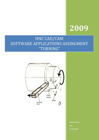
  • 9. HNC CAD/CAM SOFTWARE APPLICATIONS DAVID ANTUNA 5.1 Work piece Drawing: The following diagram shows an example of work piece that could be machine/turn in a lathe. This drawing was made using the design software AUTO CAD. Table 2 Process of Turning 9
  • 10. HNC CAD/CAM SOFTWARE APPLICATIONS DAVID ANTUNA 5.2 Calculation of Optimum Cutting Speeds: The following are the results from the calculations made for the cuttings speeds displayed below. The calculations where made using the following equation: ������������������������ ������������������������ RPM = = ������������������������������������������������������������������������������ ������������������������������������������������������������ CALCULATION OF OPTIMUM CUTTING SPEEDS FOR HARDENED STEEL DIAMETER OF SHAFT IN MM FEED RATE IN MM/Min. RPM 20 15000 238.7324146 40 15000 119.3662073 60 15000 79.57747155 CALCULATION OF OPTIMUM CUTTING SPEEDS FOR BRONZE DIAMETER OF SHAFT IN MM FEED RATE IN MM/Min. RPM 20 24000 381.9718634 40 24000 190.9859317 60 24000 127.3239545 CALCULATION OF OPTIMUM CUTTING SPEEDS FOR BRASS DIAMETER OF SHAFT IN MM FEED RATE IN MM/Min. RPM 20 45000 716.1972439 40 45000 358.098622 60 45000 238.7324146 CALCULATION OF OPTIMUM CUTTING SPEEDS FOR ALUMINIUM DIAMETER OF SHAFT IN MM FEED RATE IN MM/Min. RPM 20 75000 1193.662073 40 75000 596.8310366 60 75000 397.8873577 10
  • 11. HNC CAD/CAM SOFTWARE APPLICATIONS DAVID ANTUNA This scatter graph displays the optimum cutting speeds for the various metals shown in this report. CUTTING SPEEDS 1400 1200 HARDENED STEEL 1000 BRONZE 800 BRASS R P M 600 ALUMINIUM 400 200 0 0 10 20 30 40 50 60 70 DIAMETER OF SHAFT IN MM Table 3 Cutting Speed Calculations. 11
  • 12. HNC CAD/CAM SOFTWARE APPLICATIONS DAVID ANTUNA 6. Calculation of Power Required for Machining Operations. The table below displays the results of the calculations of the power required to turn Ø100 mm bar at the various speeds. The following equation was used: ������������������������������ ������ ������������������������������������������ ������ ������������������������������������������������������(������������������ ������������������ ������������������) Power (W) = ������������ CALCULATION OF POWER REQUIRED FOR CUTTING OPERATIONS SPEED IN DIM. OF SHAFT IN MM RADIUS OF SHAFT IN MM REV/MIN CUTTING FORCE IN (N) POWER 100 0.05 40 350 73.30 100 0.05 80 350 146.61 100 0.05 160 350 293.22 100 0.05 320 350 586.43 POWER REQUIRED FOR MACHINING OPERATIONS 700.00 600.00 P 500.00 O Power 400.00 W steel 300.00 E 200.00 Bronze R 100.00 Brass 0.00 Aluminium 0 50 100 150 200 250 300 350 SPEED IN REV PER MIN. Table 4 Power Required for Machining Operation 12
  • 13. HNC CAD/CAM SOFTWARE APPLICATIONS DAVID ANTUNA As we can see from the table above, the higher the revolution per minute the higher the power is required to cut/machine an object, in this case a solid shaft of 100mm of diameter. These actions also influences on the tool life, the reason is simple, as it is stated above, the higher the revs/min the higher the power is required therefore the harder the tool has to work. In this report we have taken four kinds of metal, hardened steel, bronze, brass and aluminium, so if bronze is taking as a example we can deduct that it will be harder to machine, therefore it will need a low set of feed and speed and doing so it will required just the correct amount of power to do the job. A company that it’s main activity is machining parts, i.e. A nuts and bolts factory, will depend in it’s ability to maximize the use of the cutting tools, therefore all the machinery must work with the optimum set up (cutting speed, feed rate & depth of cut) to make the most of every cutting tool. 13
  • 14. HNC CAD/CAM SOFTWARE APPLICATIONS DAVID ANTUNA 7. Conclusion: In this report we have learned that in the process of cutting/machining in the context of TURNING, there is a very fine balance between setting up the optimum cutting speed, feed rate and depth of cut. This balance if is apply correctly it should create the maximum level of working condition to obtain the best results from the job in hand. 14
  • 15. HNC CAD/CAM SOFTWARE APPLICATIONS DAVID ANTUNA 8. References: World Wide In-Text Reference End Note Web Example List Example Document on The phrase Brown & Electronic Source WWW speeds and Sharpe, Wikipedia the free Encyclopedia. feeds refers to Automatic 26 Nov. 2009 (last revision) two separate Screw Machine velocities in Handbook: http://en.wikipedia.org/wiki/Feed_rate machine tool Brown and practice. Sharpe Speeds and Feeds Chart, p. 222 & 223 Document on Feed rate is Brown & Electronic Source WWW the velocity at Sharpe, Wikipedia the free Encyclopedia. which the Automatic 26 Nov. 2009 (last revision) cutter is fed. Screw Machine Handbook: http://en.wikipedia.org/wiki/Feed_rate Document on The spindle Brown & Electronic Source WWW speed is the Sharpe, Wikipedia the free Encyclopedia. rotational Automatic 26 Nov. 2009 (last revision) frequency of Screw Machine. http://en.wikipedia.org/wiki/Spindle_speed the spindle of the machine. Document on The easiest Fox Valle Electronic Source WWW cutting Technical Put on Fox Valle Technical College in year 2000. parameter to College. http://its.fvtc.edu/machshop4/Carbcut/Cutspeeds.htm adjust is the Machine Shop depth of cut. web pages. Document on Cutting speed Brown & Electronic Source WWW may be Sharpe, Cam & Wikipedia the free Encyclopedia. defined as the Tool Design: 26 Nov. 2009 (last revision) rate (or speed) Surface Cutting http://en.wikipedia.org/wiki/Cutting_speed that the Speeds Chart, p. material 5 moves past the cutting edge of the tool. Picture on the The term Copyright © Electronic Source 2009 eFunda, WWW "facing" is Inc. Efunda TURNING used to describe http://www.efunda.com/processes/machining/turn.cfm removal of material from the flat end of a cylindrical part. 15
  • 16. HNC CAD/CAM SOFTWARE APPLICATIONS DAVID ANTUNA 9. Report Definitions: The following is a list of definitions of the structural points that composed this report. Title Page: The Title page is the very first page of a report and can be composed form only text with the information about the course to a very elaborate visual page with colour and pictures about the subject in the report. Summary: The summary is a shorten version of the subject that has been said or written in a report or a discussion, containing only the main points. Table of Contents: This is the page where the content of a report is listed, including pictures, graphs, tables and external work, all it is shown with its page number. Introduction: The introduction is the section at the beginning of a report that summarizes what it is about, also gives the reader the basic facts or skills in a field. Body/Discussions: This is the main part of a report, when the subject in the report is presented with all its facts, all the research done and all the support work. i.e. graphs, tables, photographs etc... Conclusions: This is the part in a report where after looking in to all the discussions within the report it brings it in to a formal closure. References: The reference states to the reader in a list or table of all the information use to help to complete the report from authors other that the creator of the report. Appendices: This part in the document is where is set all the separate material that are part of the report but it has not been made by the creator of the same. Acknowledgments: In this section of the report the author thanks those who have help in the making of the report. 16