Call Girls Pune Just Call 9907093804 Top Class Call Girl Service Available
Servo controller service manual
1. SERVO CONTROLLER
INTRODUCTION:
Sdtork Introduce Digital Servo Controller with several Features for all type of
Valve Automation.
AIM:
Sdtorks main aim is to make automation in all industries so here we are introducing our
Servo Controller to satisfy our customer with several Features inbuilt. We only the
Manufacturer who thinks about customers requirement so now we are introducing our
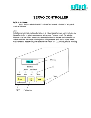
Servo Controller with Valve Opening and Closing Position with Digital Display. Open,
Close and Run mode facility with feather touch button and LED Display Shown in the fig
1
Display
000.00
Position LED
Servo Controller
Open Run Cal Close
Close
Open Cal Close
A/M
Open Calibration
2. PROCEDURE:
Make all the connections properly i.e. Motor feedback and current input. Now switch
‘ON’ the instrument, the display reads the present value. To calibrate press and hold
“CAL’ (A/M) button for about 5 seconds, now the display reads ‘CAL’ and starts flashing
slowly. Then give Input of 4 mA and press ‘CLOSE’ button on Servo the actuator starts
rotating in close direction and display starts flashing little fast. After complete close
Position the motor stops and again the display starts flashing slowly. Now give Input of
20 mA and press ‘OPEN’ button on Servo, the actuator starts opening and the display
flashes little fast again. After complete open position the motor stops and display reads
CAL without flashing. Now press and hold CAL(A/M) button for about 5 seconds to come
out of the calibration mode. The output current of 4-20mA will be calibrated automatically
during this calibration process.
For Setting the Hysteresis switch off the power and press the CAL Button and switch on
the power servo will display ‘H01’ Increases the Hysteresis by pressing the open Button
after setting the Hysteresis press the CAL Button to set the value what you have
selected and if you want the pulse operation Switch off the supply and press the Close
Button and switch on the supply the servo will read ‘NO1’ then to increase the pulse
operation press the open button and set the value and press the CAL button to fix the
value and you can see the pulse operation.
O/P 4-20mA I/P 4-20mA FB
+ - + - + -
1 2 3 4 5 6
F
u
s
e
230V
AC 1 2 3 4 5 6
5A
L N E Open Com Close
230VAC
To Actuator
3. As per the terminals shown give the connection and see the feed back whether it is pot
meter feedback or 4-20 mA feedback and give the feedback as per the specification and
assure that the input 4-20mA current is given to the servo from the Source, PLC etc and
set 4mA in the source and check the output in the source
4. SERVO CONTROLLER
BE-8100
SPECIFICATIONS
1. Operating Voltage : 230VAC (Optoional-110VAC, 24VAC)
2. Display Indication : 0 to 100% for Valve Opening
3. LED Indications : For Valve Opening/Closing and
Auto/Man
4. Control Input : 4-20mA, 0-1VDC, 0-10VDC
5. Feed Back Output : 4-20mA
6. Feed Back Input : Resistive or 4-20mA
7. Control Output : 230VAC for Motor for Opening/Closing
8. Auto/Manual Selection
Auto Mode : Valve Operates according to control
Input given
Manual Mode : Valve Operates by pressing Open/Close
Keys provided on the front panel
9. Calibration : Auto Calibration facility provided
10. Enclosure : 96(w) x96(h) x110(d) mm
5. Operating Instructions
Servo Controller controls Opening/Closing function of the Valve fitted with Electrical
Actuator. Supply, Feed Back, Motor and Input connections should be properly wired as
per the terminal details mentioned in the back panel. One key is provided to select Auto
or Manual mode. Selected mode is indicated by LED. In manual mode valve can be
operated by pressing the Open/Close feather touch keys provided on the front panel. In
Auto mode valve operates depending upon the 4-20mA input variation. At 4mA the valve
closes fully and at 20mA the valve opens fully. Accordingly for 4-20mA input variation
valve operates close to open 0 to 100% linearly. The display indicates the percentage
opening position of the valve from 0 to 100% accordingly. While valve opening/closing
takes place the corresponding LED glows. 4-20mA feedback output is available for 0 to
100% valve operation.
Calibration
To calibrate the valve with controller auto calibration facility is provided. Connect the
controller with actuator and confirm the feedback, motor and input connections are ok.
To calibrate press and hold the CAL (A/M) key for about 5 seconds. The display reads
CAL with flashing slowly. Now give input of 4mA and press Zero (close) key. The display
flashes little fast and the valve starts closing. After full close the display flashes again
slowly, now give the input of 20mA and press Span (open) key, the valve starts opening
and after full open the display reads CAL without flashing. Now press and hold the CAL
key for about 5 seconds to come out of the calibration mode. Now the valve is calibrated
with controller and starts to operate as per the input given.
Fault Indications
If the feedback is not connected properly or the value of the feedback input is exceed the
range the instrument displays FB with flashing.
While calibrating if the feedback is not proper or input 4-20mA is exceed the range or
input is not given as explained in the calibration procedure then display reads Err with
flashing.
6. Troubleshooting
Symptom Cause/ Check Point Remedy
Actuator not functioning Check power supply Check power supply
Actuator wiring not proper Correct wiring
Incorrect Voltage supply Check the input
supply voltage
suitable for actuator
Overload Check operating
thrust and rated thrust
Control Signal not available Check control signal
and provide 4-20 mA
Fault in electronics/ failure of electronic Consult Factory
card
Actuator does not open or Check limit switch settings Calibrate Limit
close completely switch settings
High valve torque required Select actuator
having higher torque
rating
Valve choked/ locked Open and Clean
valve internally
Motor runs but valve does Mechanical connection between actuator Repair or contact
not move and valve stem broken sdtork.
Motor does not run Incorrect voltage Provide correct
voltage
Improper wiring Correct wiring
Valve does not open or Disturbance in setting of travel limit Reset Travel Limit
close completely switches switches with cam