Fluetrader univit lit
•
0 likes•765 views

Univit is a high quality vitreous enamelled connecting flue system designed and approved for use with all fuels including gas, oil and approved solid fuels

Recommended
More Related Content
What's hot
What's hot (19)
Viewers also liked
Viewers also liked (12)
Similar to Fluetrader univit lit
Similar to Fluetrader univit lit (20)
Recently uploaded
Recently uploaded (20)
Fluetrader univit lit
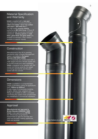
- 1. 3 Material Specification and Warranty Univit is supplied with a two year warranty and is manufactured from rolled and welded 1.2mm low carbon mild steel to BS1449 Part 1. The high quality enamel coating conforms to BS1344 Parts 1, 3 and 7 relevant to high temperature and acid resistance. Coating options of matt black, gloss black and gloss white are available as standard, other colours available on special request. Construction Manufactured in the UK to exacting standards under a Quality Management System accredited to European Standard ISO 9001:2008. The components are constructed with a male spigot end and a female socket end to provide simple and rapid installation. Univit is designed to be installed with the socket end facing upwards, the spigot end facing downwards and the joint sealed with fire cement. Dimensions Univit is available in a comprehensive range of diameters suiting all applications from 100mm to 200mm. A wide range of components including lengths, elbows, tees, adaptors and fittings are available to offer a complete connecting flue system that complements any residential or commercial installation. Approval Manufactured and approved to British Standard BS6999:1989. Univit is also approved by HETAS, the official body recognised by Government to approve biomass and solid fuel domestic heating appliances, fuels and services. www.hetas.co.uk
- 2. Univit Components 4 Straight Lengths Nominal Length 150mm 300mm 600mm 900mm 1000mm 1200mm Effective Length (L) 110mm 260mm 560mm 860mm 960mm 1160mm Ø100mm NV4*2150 NV4*2030 NV4*2060 NV4*2090 NV4*2100 NV4*21200 Ø125mm NV5*2150 NV5*2030 NV5*2060 NV5*2090 NV5*2100 NV5*21200 Ø150mm NV6*2150 NV6*2030 NV6*2060 NV6*2090 NV6*2100 NV6*21200 Ø175mm NV7*2150 NV7*2030 NV7*2060 NV7*2090 NV7*2100 NV7*21200 Ø200mm NV8*2150 NV8*2030 NV8*2060 NV8*2090 NV8*2100 NV8*21200 Ø L Straight Lengths with Access Door Nominal Length 150mm 300mm 600mm 900mm 1000mm 1200mm Effective Length (L) 110mm 260mm 560mm 860mm 960mm 1160mm Ø100mm NA NV4*3030 NV4*3060 NV4*3090 NV4*3100 NV4*31200 Ø125mm NA NV5*3030 NV5*3060 NV5*3090 NV5*3100 NV5*31200 Ø150mm NA NV6*3030 NV6*3060 NV6*3090 NV6*3100 NV6*31200 Ø175mm NA NV7*3030 NV7*3060 NV7*3090 NV7*3100 NV7*31200 Ø200mm NA NV8*3030 NV8*3060 NV8*3090 NV8*3100 NV8*31200 Ø L Adjustable Telescopic Length Two Piece Nominal Length 340mm – 550mm Effective Length (L) 300mm – 510mm Ø100mm NV4*4030 Ø125mm NV4*5030 Ø150mm NV4*6030 Ø175mm NV4*7030 Ø200mm NV4*8030 Ø L Telescopic Length One Piece Nominal Length 300mm 600mm Effective Length (L) 60mm – 250mm 60mm – 550mm Ø100mm NV4*4130 NV4*4160 Ø125mm NV5*4130 NV5*4160 Ø150mm NV6*4130 NV6*4160 Ø175mm NV7*4130 NV7*4160 Ø200mm NV8*4130 NV8*4160 Ø L Coating options of matt black, gloss black and gloss white are available as standard, other colours available on special request. Note: * Insert finish code. (B) Gloss Black (W) Gloss White (M) Matt Black
- 3. 5 90° Tee Diameter (Ø) 100mm (4”) 125mm (5”) 150mm (6”) 175mm (7”) 200mm (8”) Height (L) 298mm 298mm 298mm 298mm 348mm Centre (A) 150mm 150mm 150mm 150mm 174mm Offset (B) 124mm 140mm 152mm 163mm 175mm Code NV4*5090 NV5*5090 NV6*5090 NV7*5090 NV8*5090 A complimentary Tee Cap is supplied with Tees 135° Tee Diameter (Ø) 100mm (4”) 125mm (5”) 150mm (6”) 175mm (7”) 200mm (8”) Height (L) 305mm 328mm 335mm 400mm 430mm Centre (A) 237mm 259mm 296mm 318mm 350mm Offset (B) 141mm 156mm 191mm 209mm 234mm Code NV4*5045 NV5*5045 NV6*5045 NV7*5045 NV8*5045 A complimentary Tee Cap is supplied with Tees 30° Elbow Diameter (Ø) 100mm (4”) 125mm (5”) 150mm (6”) 175mm (7”) 200mm (8”) Height (A) 172mm 182mm 202mm 186mm 220mm Offset (B) 40mm 41mm 42mm 43mm 49mm Code NV4*6030 NV5*6030 NV6*6030 NV7*6030 NV8*6030A B Ø 45° Elbow Diameter (Ø) 100mm (4”) 125mm (5”) 150mm (6”) 175mm (7”) 200mm (8”) Height (A) 146mm 169mm 182mm 196mm 209mm Offset (B) 56mm 65mm 68mm 70mm 74mm Code NV4*6045 NV5*6045 NV6*6045 NV7*6045 NV8*6045 Ø A B 90° Elbow Swept Bend Diameter (Ø) 100mm (4”) 125mm (5”) 150mm (6”) 175mm (7”) 200mm (8”) Height (A) 135mm 138mm 155mm 171mm 185mm Offset (B) 121mm 124mm 132mm 138mm 158mm Code NV4*6090 NV5*6090 NV6*6090 NV7*6090 NV8*6090 Ø A B Note: * Insert finish code. (B) Gloss Black (W) Gloss White (M) Matt Black Not suitable for wood and solid fuels. Ø B L A Ø B L A
- 4. Components6 110° Elbow Diameter (Ø) 100mm (4”) 125mm (5”) 150mm (6”) 175mm (7”) 200mm (8”) Height (A) 140mm 159mm 177mm N/A N/A Offset (B) 87mm 92mm 107mm N/A N/A Code NV4*6110 NV5*6110 NV6*6110 90° Elbow with Access Door Swept Bend Diameter (Ø) 100mm (4”) 125mm (5”) 150mm (6”) 175mm (7”) 200mm (8”) Height (A) 121mm 124mm 132mm 138mm 158mm Offset (B) 135mm 138mm 155mm 171mm 185mm Code NV4*7090 NV5*7090 NV6*7090 NV7*7090 NV8*7090 30° Elbow with Access Door Diameter (Ø) 100mm (4”) 125mm (5”) 150mm (6”) 175mm (7”) 200mm (8”) Height (A) 172mm 182mm 202mm 186mm 220mm Offset (B) 40mm 41mm 42mm 43mm 49mm Code NV4*7030 NV5*7030 NV6*7030 NV7*7030 NV8*7030 45° Elbow with Access Door Diameter (Ø) 100mm (4”) 125mm (5”) 150mm (6”) 175mm (7”) 200mm (8”) Height (A) 146mm 169mm 182mm 196mm 209mm Offset (B) 56mm 65mm 68mm 70mm 74mm Code NV4*7045 NV5*7045 NV6*7045 NV7*7045 NV8*7045 Double 45° Offset Length Diameter (Ø) 100mm (4”) 125mm (5”) 150mm (6”) 175mm (7”) 200mm (8”) Height (L) 558mm 558mm 558mm N/A N/A Offset (B) 100mm 100mm 100mm N/A N/A Code NV4*OFF NV5*OFF NV6*OFF Note: * Insert finish code. (B) Gloss Black (W) Gloss White (M) Matt Black Not suitable for wood and solid fuels. Suitable for wood and solid fuels when used as part of the BS EN 15287 alternative methodology. For additional technical information contact sales@docherty.co.uk or call 01635 292400 B Ø A Ø A B A B Ø Ø A B Ø L B
- 5. 7 Ø C D A B 30° Offsets Diameter (Ø) 100mm (4”) 125mm (5”) 150mm (6”) 175mm (7”) 200mm (8”) Height (A) 100mm 115mm 130mm 110mm 135mm Length (B) 80mm 75mm 80mm 85mm 95mm Offset (C) 90mm 100mm 105mm 100mm 115mm Height (D) 340mm 360mm 265mm 355mm 410mm Ø C D A B Diameter (Ø) 100mm (4”) 125mm (5”) 150mm (6”) 175mm (7”) 200mm (8”) Height (A) 90mm 115mm 105mm 125mm 135mm Length (B) 80mm 85mm 90mm 100mm 105mm Offset (C) 125mm 150mm 137mm 160mm 170mm Height (D) 290mm 330mm 340mm 360mm 385mm 45° Offsets Ø C D A B Diameter (Ø) 100mm (4”) 125mm (5”) 150mm (6”) 175mm (7”) 200mm (8”) Height (A) 115mm 125mm 130mm - - Length (B) 100mm 100mm 110mm - - Offset (C) 215mm 295mm 260mm - - Height (D) 290mm 300mm 340mm - - 110° Offsets Adaptor to Flexible Liner Diameter (Ø) 100mm (4”) 125mm (5”) 150mm (6”) 175mm (7”) 200mm (8”) Height (A) 75mm 75mm 75mm 75mm 75mm Code NV4*8003 NV5*8003 NV6*8003 NV7*8003 NV8*8003 Ø A Cut Length Adaptor Diameter (Ø) 100mm (4”) 125mm (5”) 150mm (6”) 175mm (7”) 200mm (8”) Height (A) 35mm 35mm 35mm 35mm 35mm Code NV4*8004 NV5*8004 NV6*8004 NV7*8004 NV8*8004 Ø A Note: * Insert finish code. (B) Gloss Black (W) Gloss White (M) Matt Black Not suitable for wood and solid fuels.
- 6. Components8 Increaser Diameter (Ø) 100–125mm 125–150mm) 150–175mm 175–200mm Diameter (Ø) 4” - 5” 5” - 6” 6” - 7” 7” - 8” Height (A) 60mm 65mm 60mm 60mm Code NV4*8002 NV5*8002 NV6*8002 NV7*8002 Ø A Draught Regulator Diameter (Ø) 100mm (4”) 125mm (5”) 150mm (6”) 175mm (7”) 200mm (8”) Height (L) 14mm 14mm 14mm 14mm 14mm Code PH4DS PH5DS PH6DS PH7DS PH8DS Ø A Damper Unit Adaptor Diameter (Ø) 100mm (4”) 125mm (5”) 150mm (6”) 175mm (7”) 200mm (8”) Height (L) 115mm 115mm 115mm 115mm 115mm Code NV4*4100 NV5*4100 NV6*4100 NV7*4100 NV8*4100 L Ø Rosette Trim Plate One Piece Diameter (Ø) 100mm (4”) 125mm (5”) 150mm (6”) 175mm (7”) 200mm (8”) Dimension (OD) 202mm 202mm 222mm 280mm 280mm Code NV4*8001 NV5*8001 NV6*8001 NV7*8001 NV8*8001 Ø OD Rosette Trim Plate Two Piece Diameter (Ø) 100mm (4”) 125mm (5”) 150mm (6”) 175mm (7”) 200mm (8”) Dimension (OD) 202mm 202mm 222mm 280mm 280mm Code NV4*8001S NV5*8001S NV5*8001S NV7*8001S NV8*8001S Ø OD Angled Trim Plate 45° Two Piece Diameter (Ø) 100mm (4”) 125mm (5”) 150mm (6”) 175mm (7”) 200mm (8”) Dimension (OD1) 211mm 246mm 282mm 324mm 350mm Dimension (OD2) 170mm 195mm 220mm 250mm 270mm Code NV4*8001A NV5*8001A NV6*8001A NV7*8001A NV8*8001AOD1 OD2 Stainless Steel Door Diameter (Ø) 100mm (4”) 125mm (5”) 150mm (6”) 175mm (7”) 200mm (8”) Code V4X-SD V5X-SD V6X-SD V6X-SD V6X-SD Brass Door Diameter (Ø) 100mm (4”) 125mm (5”) 150mm (6”) 175mm (7”) 200mm (8”) Code V4XB-BD V5XB-BD V6XB-BD V6XB-BD V6XB-BD Note: * Insert finish code. (B) Gloss Black (W) Gloss White (M) Matt Black To be used with 900 Tee. Only to be used with wood and solid fuel if approved by the appliance manufacturer. Not to be used with a gas appliance.
- 7. 9 Door Pad Diameter (Ø) 100mm (4”) 125mm (5”) 150mm (6”) 175mm (7”) 200mm (8”) Code V4X-DP V5X-DP V6X-DP V6X-DP V6X-DP Galvanised Adjustable Wall Bracket Diameter (Ø) 100mm (4”) 125mm (5”) 150mm (6”) 175mm (7”) 200mm (8”) Code V44-WB V55-WB V66-WB V77-WB V88-WB Enamelled Adjustable Wall Bracket Diameter (Ø) 100mm (4”) 125mm (5”) 150mm (6”) 175mm (7”) 200mm (8”) Code V4*-WB V5*-WB V6*-WB V7*-WB V8*-WB Locking Band Decorative Stainless Steel Diameter (Ø) 100mm (4”) 125mm (5”) 150mm (6”) 175mm (7”) 200mm (8”) Code NV4X-JCBU NV5X-JCBU NV6X-JCBU NV7X-JCBU NV8X-JCBU Carbon Monoxide Alarm In rooms where a solid fuel appliance is installed it is a legal requirement to fit an audible CO alarm conforming to BS EN 50291, positioned in accordance with Building Regulations Approved Document J. Visit www.planningportal.gov.uk for current Building Regulations Installation Instructions Univit must only be installed by a competent approved installer and in accordance with detailed installation instructions which are available on request or can be downloaded from our website. For additional technical information contact sales@docherty.co.uk or call 01635 292400 Code CO7B Note: * Insert finish code. (B) Gloss Black (W) Gloss White (M) Matt Black Ø
- 8. 10 Warranty terms and conditions Installation Guide Univit is manufactured to the highest quality standards. Under normal operating conditions, Univit provides many years of reliable service and carries a 2 year conditional warranty depending on application, installation and maintenance. The 2 year warranty covers any defect due to faulty manufacture; this is provided the system has been installed in accordance with the installation instructions and has been used for the purpose it was designed for. Furthermore, the system must be regularly cleaned, maintained and inspected (at least once per year and more regularly if the appliance is used continuously or frequently) by a qualified chimney sweep or HETAS approved engineer. Written documentation to demonstrate the inspection and cleaning of the chimney by an appropriately qualified person must be kept to validate the two year warranty. When burning solid fuel in your appliance, care should always be taken to use a high quality fuel. Only HETAS or SFA (Solid Fuel Association) approved fuels must be used with Univit. For guidance on fuel choices please visit www.hetas.co.uk. Under no circumstances should an appliance be located where there is the potential of chemical contamination of the combustion air. A chimney fire will invalidate the warranty. In the event of a chimney fire it is always advisable to replace the complete chimney system. Univit must only be used to connect a heating appliance to a chimney and not as a flue liner within a chimney. It can only be used in the same room as the appliance and it must not be used to penetrate a wall or ceiling unless it is the wall of a masonry chimney breast. All combustion appliances require adequate ventilation to operate correctly. Ventilation should be provided in accordance with Approved Document J or the appliance manufacturers’ instructions, whichever is the greater. The connecting flue pipe run should be studied and measured accurately to reduce the need for cutting lengths and reduce joints to a minimum. All flues must have provision for cleaning and inspection both internally and externally. Where the chimney is to be swept through the connecting flue pipe then it is important to ensure a suitably sized and stiffness of brush for the flue in the chimney can pass through the pipe. If this is not the case then an additional cleaning access in the chimney will be required. If the sweeping of the chimney through the flue pipe will put strain on any of the joints, such as around bends and offsets, then additional bracketing of the connecting flue pipe will be required to avoid such damage. Univit must only be installed by a competent approved installer and in accordance with the installation instructions that are available on request. Chimney and flue design The chimney and flue design is the responsibility of the engineer or installer and should conform to the requirements of these instructions, the requirements of Approved Document J and, where appropriate, BS EN 15287 Part 1. Any variation from these instructions and the standards will require the designer to ensure the performance of the chimney meets the requirements of the appliance by calculation using the methods given in BS EN 13384 Part 1 or any proprietary software program based on this standard. Regulations and standards The regulations and standards covering the design and installation of a flue pipe in the UK are as follows: Building Regulations England and Wales - Approved Document J – Combustion Appliances and Fuel Storage Systems Scotland – Scottish Building Standards Technical Hand Book Section 3 Northern Ireland – Building Regulations Part L – Combustion Appliances and Fuel Storage Systems Standards BS EN 15287 Part 1 Chimneys. Design, installation and commissioning of chimneys Part 1: Chimneys for non-room sealed heating appliances. BS EN 13384 Part 1 – Chimneys. Thermal and fluid dynamic calculation methods. Flue sizing The sizing of flues for appliances should be based on the type of fuel and the appliance to be used. • Gas Appliances In the case of gas appliances the Building Regulations Approved Document J table 5, the gas safety in use regulations and in all cases as required by the manufacturers’ installation instructions. • Oil Appliances Flues for oil appliances should be sized in accordance with the requirements of Approved Document J Paragraphs 4.4 and 4.5. • Solid Fuel Appliances The size of flues for solid fuel appliances should be in accordance with the requirements of Approved Document J Paragraphs 2.4 to 2.7 and as given in table 2 of ADJ. Univit can be installed as close as required to non-combustible material, but should not be touching any wall or surface it is not going to be sealed and connected to. For solid fuel installations, Univit has to be positioned a minimum of three times its nominal diameter away from any combustible material. Where a shield is provided as required in Approved Document J then this distance can be reduced to 1.5 times the diameter. The shield must be of non-combustible material and have a minimum 12mm air gap between it and the combustible material it is shielding. The best possible chimney system is straight and vertical at all times, but in some cases it is necessary to have an offset in a connecting flue pipe if the chimney and appliance outlet do not line up. If this is the case then a maximum of two bends of up to 45 degrees from the vertical are allowed in a connecting flue pipe. The weight of any chimney system must not be borne by the flue pipe and it must be possible to remove the connecting flue pipe without the need to remove any other part of the flue or chimney. The connecting flue pipe must be connected to the flue in the chimney using an appropriate adaptor. This will vary depending on the type of arrangement. The adaptor may be to a flexible twin wall stainless steel flue lining, rigid clay or concrete lining, factory made steel chimney system, or into an unlined chimney via a register plate.
- 9. Full Installation Instructions on Request Adjustable Wall Sleeve Adaptor to Twin Wall Chimney 45° Vitreous Elbow with Door Vitreous Enamel Connecting Flue Maximum height of 600mm before an offset 135° Tee Wall Support Bracket Tee Cap 150mm maximum Closure Plate Vitreous Enamel Connecting Flue Top Hat Adaptor Flexible Flue Liner 90° Vitreous Tee Closure Plate Mounting Frame Tee Cap 150mm maximum Adaptor to Twin Wall Chimney Vitreous Enamel Connecting Flue 90° Vitreous Tee 150mm minimum Adjustable Wall Support 11 UnivitInstallation