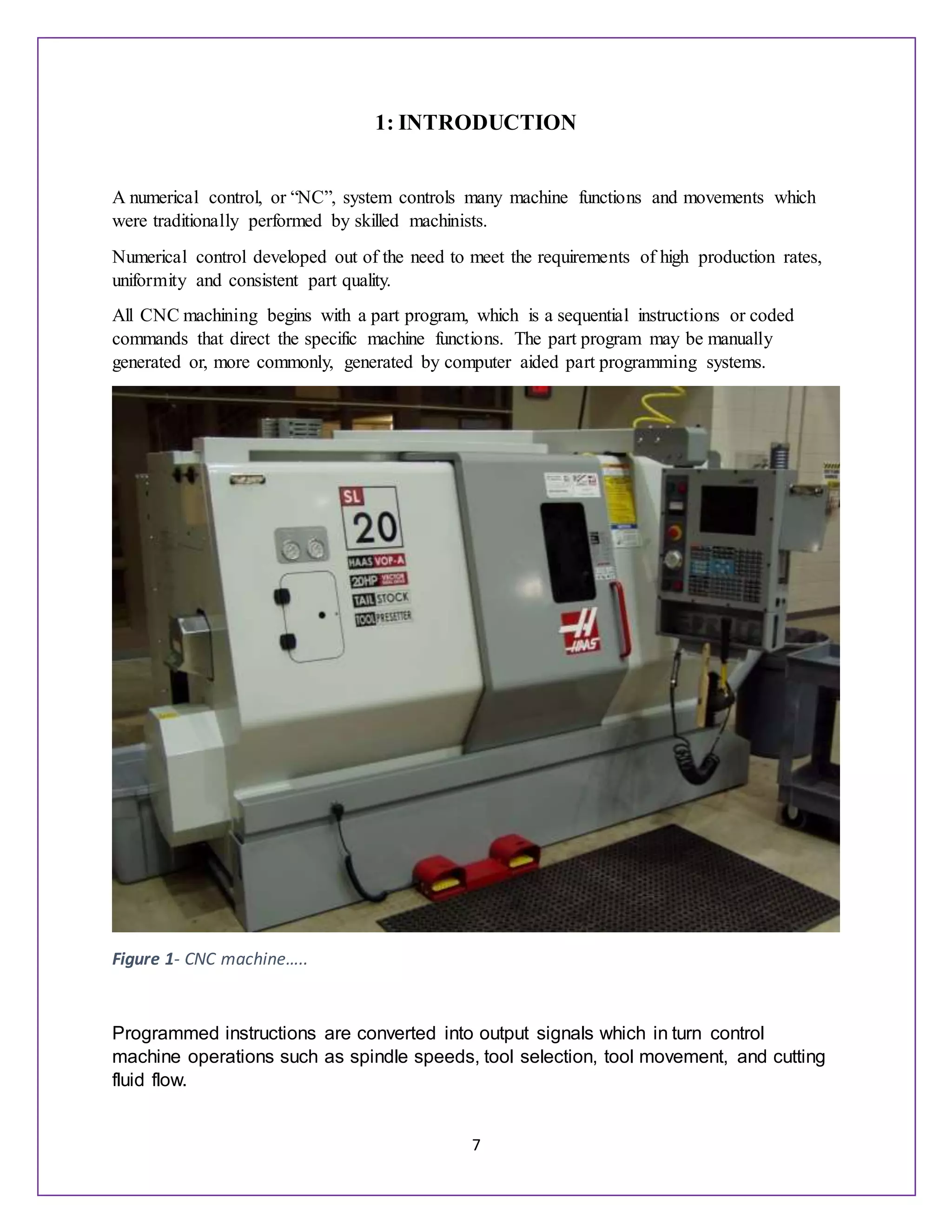
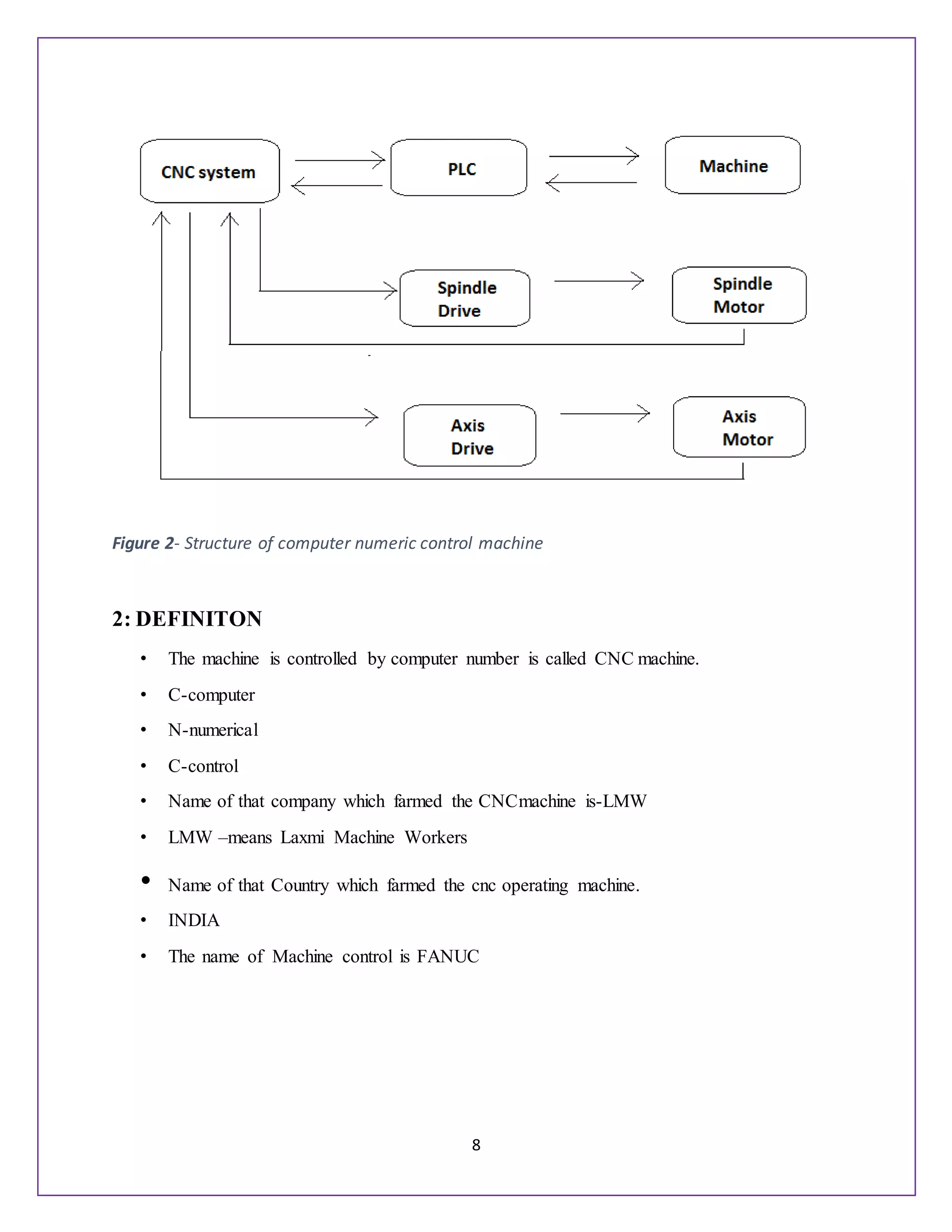
1
U.N.S. INSTITUTE OF ENGINEERING &TECHNOLOGY
V.B.S. PURVANCHAL UNIVERSITY, JAUNPUR
SEMINAR REPORT
ON
“COMPUTER NUMERIC CONTROL& PROGRAMMING”
SESSION:(2014-2015)
DEPARTMENT OF MECHANICAL ENGINEERING
SUBMITTED TO: - SUBMITTED BY:-
ER. DEEP PRAKASH SINGH YOGENDRA SINGH
LECTURER ROLL NO-212435
MECHANICAL ENGINEERING DEPARTMENT B.Tech 3rd Year(5th sem)
2
TO WHOM IT MAY CONCERN
This is to certify that Mr. Yogendra Singh (Roll No. 212435) a
student of B.Tech. 3rd
year (5th
semester) have presented a
seminar on “COMPUTER NUMERIC CONTROL &PROGRAMMING” in
Partial fulfillment for the award of degree of Bachelor of
Technology in Mechanical Engineering from Uma Nath Singh
Institute of Engineering & Technology, V.B.S. Purvanchal
University, Jaunpur,UP under our supervision and guidance
during the session 2014-2015.
CERTIFIED BY
…………………
Seminar In-charge
Er.Deep Prakash Singh (Lecturer)
Department of mechanical engineering
3
ACKNOWLEDGEMENT
I take this opportunity to express my profound gratitude and deep regards to my
seminar in charge “Er. DEEP PRAKASHSINGH” his exemplary guidance,
monitoring and constant encouragement throughout the courseof this project. The
blessing, help and guidance given by him time to time shall carry me a long way in
the journey of life on which i am about to embark.
I also take this opportunity to express a deep sense of gratitude to the Head of
Dept. of MECHANICAL ENGINEERING Er. SANDEEP KR. SINGHFOR HIS
CORDINAL SUPPORT, VALUABLE INFORMATION AND GUIDANCE,
WHICH HELPED ME IN COMPLEATING THIS Task through various stages.
Lastly, I thank my, classmates and friends for their constant encouragement
without which this assignment would not be possible.
YOGENDRA SINGH
ROLL NO – 212435
B.Tech 3rd year (5th Sem.)
4
ABSTRACT
Using CNC, whether on a professional or hobbyist level, is not only an exciting process to be
involved in but is also the direction manufacturing is heading. There are a great many facets and
stages involved in the end-to-end process of understanding and implementing CNC, and, al-
though there have been several books published on specific aspects or topics (such as G-code
programming, building a CNC machine, etc.), there have been no books written that guide the
reader through the overall process, that is, until now. It is not the intent of this book to replace
any previously written information on this topic nor to delve into any particular area. However,
by the time readers finish reading this book, they will have a solid understanding of the entire
CNC process from a top-down end-to-end perspective. More specifically, this book is intended
for the following audiences:
• Academic: This book will provide the instructor and students a very informative introduction
into applied CNC, the various machines, and their uses, along with the necessary tools used in
the process. • Business owner: The aspect of moving a small- to medium-sized business, or even
a startup company, from a manually concentric manufacturing process into the accuracy and
repeatability of what CNC has to offer, can be a daunting task. This book guides business owners
in the proper direction to help them understand and decide the ins and outs of automating their
manufacturing process. Furthermore, also discussed will be what to look forward to when
growing future CNC-based operations. • Hobbyist: There are a great number of individuals
interested in the understanding and technical aspects of CNC, but are not exactly sure where to
begin what is absolutely required for the application at hand from both a hardware and software
perspective and what is not. There are many free and low-cost software options to choose from
that are listed for the reader to appropriately determine what is needed for their particular
application.
5
CONTENT
Sr no Topic Page no
1 Introduction 7-8
2 Definition 8
3 Operation 9
4 Engineering and production system 9
5 Main element of the CNC machine 9
6 Lubrication oil & Hydraulic pressure 10
7 Dimension & Tolerance 10-12
8 Basic CNC Principles 13
9 Tooling 18-19
10 Flow of Computer-Aided CNC Processing 20
11 CNC Machine Axes of Motion 21
12 Program Command Parameters 21
13 Coding Dimensioning & Address 22
14 Address 22
15 Apt programming example 23
16 SAFTY-PPE (PERSONAL PROTECTIVE EQUIPMENT) 24
19 Bin & Action 28
20 Reference 27
.
6
LIST OF FIGURE
Figure:
no
Topic Page:
no
1 CNC machine 6
2 Structure of computer numeric control machine 7
3 condition system used in cnc machine 12
4 Working principle of cnc machine 13
5 vertical cnc machine 14
6 Tool setting of the cnc machine 15
7 Tool angle projection 16
8 Main tool of cnc machine 17
9 Cutting oil rod 18
10 cutting oil rod 18
11 Tool geometry 19
TABLE
Table no Topic Page no
1 M-CODE 23
2 G-CODE 24
7
1: INTRODUCTION
A numerical control, or “NC”, system controls many machine functions and movements which
were traditionally performed by skilled machinists.
Numerical control developed out of the need to meet the requirements of high production rates,
uniformity and consistent part quality.
All CNC machining begins with a part program, which is a sequential instructions or coded
commands that direct the specific machine functions. The part program may be manually
generated or, more commonly, generated by computer aided part programming systems.
Figure 1- CNC machine…..
Programmed instructions are converted into output signals which in turn control
machine operations such as spindle speeds, tool selection, tool movement, and cutting
fluid flow.
8
Figure 2- Structure of computer numeric control machine
2: DEFINITON
• The machine is controlled by computer number is called CNC machine.
• C-computer
• N-numerical
• C-control
• Name of that company which farmed the CNCmachine is-LMW
• LMW –means Laxmi Machine Workers
• Name of that Country which farmed the cnc operating machine.
• INDIA
• The name of Machine control is FANUC
9
3: OPERATION
• Turning Grooving
• Facing Tapering
• Radius
• Chamfer
• Threading
• Drilling
• Boring
4: ENGINEERINGAND PRODUCTION SYSTEM
• The system which is comes is used from computer machine is given following-
• CNC
• CAD
• ROBATIES- Computerized material handling.
• CAPM-Computer aided production and manufacturing;
• CAQA-Computer aided quality assurance.
• CIM-Computer integrated manufacturing.
5: MAIN ELEMENT OF CNC MACHINE
• Machine base
• Machine lamp
• Main spindle
• Chip gear door
• Tool turret
• Tail stock
• Tail stock hand
• Screen
• Control specific keyboard
Emergency off key
10
5: A: NAME OF THE PART OF THE MACHINE
• CHUCK- Jaw, Nut, Allan key
• Control Panel –keyboard ,screen
• Turret- Tool, Tool holder, Sleevepacker
• Chuck Paddle- Hydraulic Control ,Tailstock paddle
• Motor- Servo motorhydraulicmotorCoolant pipe
6: Lubrication oil & Hydraulic pressure
• Lubrication oil used to increase the smoothness of the part of machine by which part of
machine are not rugged.
• Hydraulic pressure is used to clamp and unclamp jaw. And also it rotate the turret and in
or out tailstock.
• COOLENT-coolant is also known as cutting oil which used to cooling of machine tools.
CNC OPERATING
Types of cnc
• Cnc have three types
• CNC-Turning
• VMC-vertical machining center
• HMC-horizontal machining center
• AXIS-
• CNC-X,Z axis
• VMC-X,Y,Z
• HMC-X,Y,Z
• Where x-axis is used for work piece dia.
• Where z-axis is used for work piece length
11
7: Dimension &Tolerance
• TOLERANCE-it is a difference between lower limit to higher limit.
• For example50+-0.3
• Basic size 50
• Upper limit-50.3
• lower limit-49.7
• Tolerence-0.6
• There are three type to acceptable the limit are given below-
• Dimensionally
• Visually
• Fictionally
•
How many controlled is used in India?
• Fanuc- 0/10/11/12/15 series (Germany, USA, Fanuc, Japan )
• Sinumric—810/820/840 series(semen’s, Germany)
• Sinumisic 3 series(semen’sGermany)
• Allen Bradley 8600 Series (USA)
• HaidenHani (Germany)
• Kirloskarn ELEC.CO (ANILAM UK)
• HINUMERIC (HMT INDIA)ANCA (Australia)
• How many inches used in chuck & Typesof chuck?
• Tow Jaw , Three Jaw ,Four Jaw chuck
• Inches of chuck is given below—
• 3, 4, 6, 8, 9, 12, 14, 16, 18, 20, 22, & 24.inches
• How many types of turret
• Turret are eight types but size of every turret is different. Following are given below-
• Four Turret(in which four tool are used)
12
• Six turret,
• Eight turret
• Ten turret
• Twelve turret
• Fourteen turret
• Sixteen turret
• Eighteen turret
How many types of hydraulicoils are used in cnc machine?
• In cnc machine hydraulic oils are used which is filled by the number.
• Hydraulic oil number are following-
• 68 & 32
• How much water is filled into the cnc’s tank
• In the cnc machine tank 100 liter water is filled with 5 liter coolant oil.
13
8: Basic CNC Principles
All computer controlled machines are able to accurately and repeatedly control motion in
various directions. Each of these directions of motion is called an axis. Depending on the
machine type there are commonly two to five axes.
Additionally, a CNC axis may be either a linear axis in which movement is in a straight line, or a
rotary axis with motion following a circular path.
Figure 3-condition system used in cnc machine
Each axis consists of a mechanical component, such as a slide that moves, a servo drive motor
that powers the mechanical movement, and a ball screw to transfer the power from the servo
drive motor to the mechanical component. These components, along with the computer
controls that govern them, are referred to as an axis drive system.
14
Figure 4-Working principle of cnc machine
If a rotary table is added to the machine table, then the fourth axis is designated the “b” axis.
15
Figure 5: vertical cnc machine
16
Figure 6: Tool setting of the cnc machine
If a rotary table is added to the machine table, then the fourth axis is designated the “b” axis.
17
Figure 7: Tool angle projection
Work Positioning
The method of accurate work positioning in relation to the cutting tool is called the “rectangular
coordinate system.” On the vertical mill, the horizontal base line is designated the “X” axis,
while the vertical base line is designated the “Y” axis. The “Z” axis is at a right angle,
perpendicular to both the “X” and “Y” axes.
Increments for all base lines are specified in linear measurements, for most machines the
smallest increment is one ten-thousandth of an inch (.0001). If the machine is graduated in metric
the smallest increment is usually one thousandth of a millimeter (.001mm).
The rectangular coordinate system allows the mathematical plotting of points in space. These
points or locations are called “coordinates.” The coordinates in turn relate to the tool center and
dictate the “tool path” through the work
18
9: TOOLING.
Within the machining and CNC world, the term tooling simply means the cutter you intend to
use. There are a great many categories of tooling that can be used and are somewhat specific to
the type of machine and material you will be working with. There are so many different types of
tooling that are associated with each facet of CNC machining that it would take a separate book
to cover them all. What we will do here is cover some of the basic types that are typically
associated with wood and plastic routing, as well as engraving. Also bear in mind that the tools
listed here are available both as SAE and metric dimensions. The picture shown here shows an
array of up-cut end mill bits that range from 1/8- to 1/2-in diameter along with some 120- and
150-degree herself v-bit cutters.
• End mill. You could consider the end mill as the workhorse bit most widely used in
CNC milling operations.
Are specific to the type of material you are working with as well (i.e., wood, composites, solid
surface, plastics, and metals). End mills are used in profiling, area clearance, drilling, and inlay
types of operations. Among the types of end mills you will typically use: up cut, down cut,
compression (up and down cut), roughing, and finishing • Ball nose. These types of bits differ
from end mills in that the geometry of the end of the bit is rounded. These bits are also available
in various types and are often used in areas such as decorative fluting, engraving, and in 3D
finish work. • Engraving. Virtually any style of bit can be used for engraving. How- ever, when
you focus your attention more on using a CNC engraving
Figure 8 Main tool of cnc machine
19
Machine and working
With specific engraving stock (see both http:// rowmark.com/ and http://www.inoplas.com/ for
just a sampling of material types), then the primary style of engraving tool is the conical bit
although V-bits are common in engraving operations.
The process of fine engraving uses an entirely different set of tooling. They are aptly named
conical, as the tips of the cutters are shaped like a cone, and each have a specific flat spot ground
on the tip. These are the long version that work with most engraving machines (this is a full set)
and require specialized collets and a high-speed spindle to drive them. They are also available in
1/4-in shank versions for users who have a router or spindle chuckthe particular vendor of these
bits, Antares, has a detailed description of the anatomy and intended uses of these bits:
http://www. antaresinc.net/FactCutterGeometry.html. There are also specialized types of these
cutters that are used in producing signage that complies with the American Disabilities Act
Figure 9 Cutting oil rod
Figure 10 cutting oil rod
20
(ADA). Among these are specific angled cutters for material overlay profiling, as well as dot
cutters for working with Braille for the visually impaired.
For metal-working mills, there is a system that works with common metalworking tooling
and is called the Tarmac tooling system (TTS). If you do much work on a mill, this tooling
addition can improve both your time and accuracy. It works as a series of tool holders that
quickly adapt to your existing collet system (R8 or MT3) to change out tools. Each holder
fits into the collet the same distance and the protruding amount of the tool is a user-
measured distance that gets stored in a file within the controller
21
10:Flow of Computer-Aided CNC Processing
• Develop or obtain the 3D geometric model of the part, using CAD.
• Decide which machining operations and cutter-path directions are required
(computer assisted).
• Choose the tooling required (computer assisted).
• Run CAM software to generate the CNC part program.
• Verify and edit program.
• Download the part program to the appropriate machine.
• Verify the program on the actual machine and edit if necessary.
Figure 11 Tool geometry
22
• Run the program and produce the part.
11:CNC Machine Axes of Motion
The coordinate system used for the tool path must be identical to the coordinate
System used by the CNC machine. The standards for machine axes are established according to
the industry standard report EIA RS-267A.
12:ProgramCommand Parameters-
Optimum machine programming requires consideration of certain machine operating parameters
including:
• Positioning control
• Compensations
• Special machine features
Positioning control is the ability to program tool and machine slide movement simultaneously
along two or more axes. Positioning may be for point-to-point movement or for contouring
movement along a continuous path. Contouring requires tool movement along multiple axes
simultaneously. This movement is referred to as “Interpolation” which is the process of
calculating intermediate values between specific points along a programmed path and outputting
those values as a precise motion. Interpolation may be linear having just a start and end point
along a straight line, or circular which requires an end point, a center and a direction around the
arc.
• CNC instructions are called part program commands.
• When running, a part program is interpreted one command line at a time until all lines
are completed.
• Commands, which are also referred to as blocks, are made up of words which each
begin with a letter address and end with a numerical value.
Important things to know:
• Coordinate System
23
• Units, incremental or absolute positioning
• Coordinates: X,Y,Z, RX,RY,RZ
• Feed rate and spindle speed
• Coolant Control: On/Off, Flood, Mist
13:Coding Dimensioning& Address
• M-CODE
• G-CODE
• DIMENSION
• ADDRESS
14:ADDRESS
• A-Angle Q-Depth of cut in micron
• C- Chamfer R-Radius
• D-Work piece dimension S-Spindle speed
• F-Feed T-Tool function
• I-Radius value on x-axis V-Incremental command of x-axis
• K-Radius value on z-axis W-Incremental command of z-axis
• N-Numerical no X-x-axis
P-Dwell time/sub program call Z-Axis
15: M-Codes
Codes that begin with M are called miscellaneous words. They control machine auxiliary options
like coolant and spindle direction. Only one M-code can appear in each block of code.
24
The table below lists the most common M codes and their meaning. A complete list of M-codes
is included in Apex D - G-M Codes Reference TABLE NO-1
16: G-Codes
Codes that begin with G are called preparatory words because they prepare the machine for a
certain type of motion. The most common G-codes are shown in Table 5.3 and a complete list
and their meaning is included in Apex D - G-M Codes Reference
Code Meaning
M0 Program stop. Press Cycle Start button to continue.
M1 Optional stop. Only executed if Op Stop switch on the CNC control is turned ON.
M2 End of program.
M3 Spindle on Clockwise.
M4 Spindle on Counter clockwise.
M5 Spindle stop.
M6 Change tool.
M8 Coolant on.
M9 Coolant off.
M30 End program and press Cycle Start to run it again.
25
TABLE NO-2
CODE MEANING
G0 Rapid motion. Used to position the machine for non-milling moves.
G1 Line motion at a specified feed rate
G2 Clockwise arc
G3 Counter clockwise arc.
G4 Dwell
G28 Return to machine home position.
G40 Cutter Diameter Compensation (CDC) off.
G41 Cutter Diameter Compensation (CDC) left
G42 Cutter Diameter Compensation (CDC) right
G43 Tool length offset (TLO).
G54 Fixture Offset #1.
G55 Fixture Offset #2.
G56 Fixture Offset #3.
G57 Fixture Offset #4.
G58 Fixture Offset #5.
G59 Fixture Offset #6.
G80 Cancel drill cycle
G81 Simple drill cycle
G82 Simple drill cycle with dwell.
G83 Peck drill cycle.
G84 Tap cycle
G90 Absolute coordinate programming mode.
G91 Incremental coordinate programming mode.
G98 Drill cycle return to Initial point (R).
G99 Drill cycle return to Reference plane (last Z Height)
.
26
17:APT Programming Example
Cylindrical Part
APT Programming Example-Cylindrical Part
Fig: 12-example of programming
20
Raw Material
Finished Part
70
30
17
.5

22
.5

25
27
O0013
N0005 G53
N0010 T0303
N0020 G57 G00 X26.00 Z0.0 S500 M04
N0030 G01 X-0.20 F100
N0040 G00 Z2.0
N0050 X50.0 Z50.0
N0060 T0404
N0070 G57 G00 X22.50 Z2.0 S500
N0080 G01 Z-30.0 F100
N0090 G00 X23.0 Z2.0 S500
N0100 G84 X17.5 Z-20.0 D0=200 D2=200 D3=650
N0110 G00 Z2.0
N0120 X50.0 Z50.0
N0130 M30
From here-
 O0013
Program identification number
 N0005 G53
To cancel any previous working zero point
 N0010 T0303
 N0010 Sequence number
T0303 Select tool number 303
 N0020 G57 G00 X26.0 Z0.0 S500 M04
 G57 To set the working zero point as saved
G00 Rapid movement (no cutting)
X26.0 X location (as a diameter; 13 form zero)
Z0.0 Z location
S500 Spindle speed is 500 rpm
M04 Rotate spindle counterclockwise
 N0030 G01 X-0.20 F100
 G01 Linear interpolation (cutting)
X-0.20 Move only in x direction until you pass
the center by 0.1 mm (facing)
F100 Set feed rate to 100 mm/min
 N0040 G00 Z2.0
 G00 Move rapidly away from work piece (no cutting)
Z2.0 the movement is 2 mm away from the face.
 N0050 X50.0 Z50.0
 Go to a safe location away from the work piece [x = 50 (25 from zero), z = 50] to change
the tool.
28
 N0060 T0404
 T0404 Select tool number 404
 N0070 G57 G00 X22.50 Z2.0 S500
 G57 PS0
G00 Rapid movement (no cutting)
X22.50 X location (as a diameter; 11.25 form zero)
Z2.0 Z location
S500 Spindle speed is 500 rpm
 N0080 G01 Z-30.0 F100
 G01 Linear interpolation (cutting)
Z-30 Move only in z direction (external turning)
F100 Set feed rate to 100 mm/min.
 N0090 G00 X23.0 Z2.0 S500
 G00 Move rapidly away from work piece (no cutting) to location x= 23.0 (11.50 from
zero) and z = 2.0.
 N0100 G84 X17.5 Z-20.0 D0=200 D2=200 D3=650
 G84 Turning cycle for machining the step
X17.5 final diameter
Z-20 length of step is 20 mm
D0=200 Finish allowance in X direction (0.2 mm) D2=200 Finish allowance in Z
direction (0.2 mm)
D3=650 Depth of cut in each pass (0.65 mm)
 N0110 G00 Z2.0
 G00 Move rapidly away from work piece (no cutting)
Z2.0 the movement is 2 mm away from the face.
 N0120 X50.0 Z50.0
 X50.0 Z50.0 Move to the tool changing location
 N0130 M30
 M30 Program End
29
18:SAFTY- PPE (PERSONALPROTECTIVE EQUIPMENT)
• HAND GLOVES
• MOUTH MASK
• EAR PLUG
• APRON
• SAFTY BELT
• GOGGLES
• SAFTY SHOES
• HALMET
19:BIN & ACTION
• Red bin (rejected material)
• Yellow bin (rework able material)
• Green bin (Acceptable material)
• Blue bin (transportation)
• CORRECTIVE ACTION (REPRAPARE MATERIAL AFTER ERROR)
PREVETIVE ACTION (ALREADY PRAPARED MATERIAL BEFORE ERROR)
30
20:REFERENCES
 www.nplindia.org
 www.wikpedia.org
 www.fortune.com
 www.headland.com
 www.machinetoolhelp.com
 www.cncezpro.com
 www.slidesheare.com
 I.C.GROVER, “CAD/CAM”, published by Macmillan
 NARANG, “Introduction to Numerical Control”
 P.S.GILL and KRAR, “Fundamental of Numeric Control”
 STEVE KRAR & ARTHUR GILL, “CNC Technology and Programming”,
published by McGraw Hill
 Members of the Mechanical Workshop, National Physical Laboratory, New Delhi

Yogendra singh final report (2)

  • 1.
    1 U.N.S. INSTITUTE OFENGINEERING &TECHNOLOGY V.B.S. PURVANCHAL UNIVERSITY, JAUNPUR SEMINAR REPORT ON “COMPUTER NUMERIC CONTROL& PROGRAMMING” SESSION:(2014-2015) DEPARTMENT OF MECHANICAL ENGINEERING SUBMITTED TO: - SUBMITTED BY:- ER. DEEP PRAKASH SINGH YOGENDRA SINGH LECTURER ROLL NO-212435 MECHANICAL ENGINEERING DEPARTMENT B.Tech 3rd Year(5th sem)
  • 2.
    2 TO WHOM ITMAY CONCERN This is to certify that Mr. Yogendra Singh (Roll No. 212435) a student of B.Tech. 3rd year (5th semester) have presented a seminar on “COMPUTER NUMERIC CONTROL &PROGRAMMING” in Partial fulfillment for the award of degree of Bachelor of Technology in Mechanical Engineering from Uma Nath Singh Institute of Engineering & Technology, V.B.S. Purvanchal University, Jaunpur,UP under our supervision and guidance during the session 2014-2015. CERTIFIED BY ………………… Seminar In-charge Er.Deep Prakash Singh (Lecturer) Department of mechanical engineering
  • 3.
    3 ACKNOWLEDGEMENT I take thisopportunity to express my profound gratitude and deep regards to my seminar in charge “Er. DEEP PRAKASHSINGH” his exemplary guidance, monitoring and constant encouragement throughout the courseof this project. The blessing, help and guidance given by him time to time shall carry me a long way in the journey of life on which i am about to embark. I also take this opportunity to express a deep sense of gratitude to the Head of Dept. of MECHANICAL ENGINEERING Er. SANDEEP KR. SINGHFOR HIS CORDINAL SUPPORT, VALUABLE INFORMATION AND GUIDANCE, WHICH HELPED ME IN COMPLEATING THIS Task through various stages. Lastly, I thank my, classmates and friends for their constant encouragement without which this assignment would not be possible. YOGENDRA SINGH ROLL NO – 212435 B.Tech 3rd year (5th Sem.)
  • 4.
    4 ABSTRACT Using CNC, whetheron a professional or hobbyist level, is not only an exciting process to be involved in but is also the direction manufacturing is heading. There are a great many facets and stages involved in the end-to-end process of understanding and implementing CNC, and, al- though there have been several books published on specific aspects or topics (such as G-code programming, building a CNC machine, etc.), there have been no books written that guide the reader through the overall process, that is, until now. It is not the intent of this book to replace any previously written information on this topic nor to delve into any particular area. However, by the time readers finish reading this book, they will have a solid understanding of the entire CNC process from a top-down end-to-end perspective. More specifically, this book is intended for the following audiences: • Academic: This book will provide the instructor and students a very informative introduction into applied CNC, the various machines, and their uses, along with the necessary tools used in the process. • Business owner: The aspect of moving a small- to medium-sized business, or even a startup company, from a manually concentric manufacturing process into the accuracy and repeatability of what CNC has to offer, can be a daunting task. This book guides business owners in the proper direction to help them understand and decide the ins and outs of automating their manufacturing process. Furthermore, also discussed will be what to look forward to when growing future CNC-based operations. • Hobbyist: There are a great number of individuals interested in the understanding and technical aspects of CNC, but are not exactly sure where to begin what is absolutely required for the application at hand from both a hardware and software perspective and what is not. There are many free and low-cost software options to choose from that are listed for the reader to appropriately determine what is needed for their particular application.
  • 5.
    5 CONTENT Sr no TopicPage no 1 Introduction 7-8 2 Definition 8 3 Operation 9 4 Engineering and production system 9 5 Main element of the CNC machine 9 6 Lubrication oil & Hydraulic pressure 10 7 Dimension & Tolerance 10-12 8 Basic CNC Principles 13 9 Tooling 18-19 10 Flow of Computer-Aided CNC Processing 20 11 CNC Machine Axes of Motion 21 12 Program Command Parameters 21 13 Coding Dimensioning & Address 22 14 Address 22 15 Apt programming example 23 16 SAFTY-PPE (PERSONAL PROTECTIVE EQUIPMENT) 24 19 Bin & Action 28 20 Reference 27 .
  • 6.
    6 LIST OF FIGURE Figure: no TopicPage: no 1 CNC machine 6 2 Structure of computer numeric control machine 7 3 condition system used in cnc machine 12 4 Working principle of cnc machine 13 5 vertical cnc machine 14 6 Tool setting of the cnc machine 15 7 Tool angle projection 16 8 Main tool of cnc machine 17 9 Cutting oil rod 18 10 cutting oil rod 18 11 Tool geometry 19 TABLE Table no Topic Page no 1 M-CODE 23 2 G-CODE 24
  • 7.
    7 1: INTRODUCTION A numericalcontrol, or “NC”, system controls many machine functions and movements which were traditionally performed by skilled machinists. Numerical control developed out of the need to meet the requirements of high production rates, uniformity and consistent part quality. All CNC machining begins with a part program, which is a sequential instructions or coded commands that direct the specific machine functions. The part program may be manually generated or, more commonly, generated by computer aided part programming systems. Figure 1- CNC machine….. Programmed instructions are converted into output signals which in turn control machine operations such as spindle speeds, tool selection, tool movement, and cutting fluid flow.
  • 8.
    8 Figure 2- Structureof computer numeric control machine 2: DEFINITON • The machine is controlled by computer number is called CNC machine. • C-computer • N-numerical • C-control • Name of that company which farmed the CNCmachine is-LMW • LMW –means Laxmi Machine Workers • Name of that Country which farmed the cnc operating machine. • INDIA • The name of Machine control is FANUC
  • 9.
    9 3: OPERATION • TurningGrooving • Facing Tapering • Radius • Chamfer • Threading • Drilling • Boring 4: ENGINEERINGAND PRODUCTION SYSTEM • The system which is comes is used from computer machine is given following- • CNC • CAD • ROBATIES- Computerized material handling. • CAPM-Computer aided production and manufacturing; • CAQA-Computer aided quality assurance. • CIM-Computer integrated manufacturing. 5: MAIN ELEMENT OF CNC MACHINE • Machine base • Machine lamp • Main spindle • Chip gear door • Tool turret • Tail stock • Tail stock hand • Screen • Control specific keyboard Emergency off key
  • 10.
    10 5: A: NAMEOF THE PART OF THE MACHINE • CHUCK- Jaw, Nut, Allan key • Control Panel –keyboard ,screen • Turret- Tool, Tool holder, Sleevepacker • Chuck Paddle- Hydraulic Control ,Tailstock paddle • Motor- Servo motorhydraulicmotorCoolant pipe 6: Lubrication oil & Hydraulic pressure • Lubrication oil used to increase the smoothness of the part of machine by which part of machine are not rugged. • Hydraulic pressure is used to clamp and unclamp jaw. And also it rotate the turret and in or out tailstock. • COOLENT-coolant is also known as cutting oil which used to cooling of machine tools. CNC OPERATING Types of cnc • Cnc have three types • CNC-Turning • VMC-vertical machining center • HMC-horizontal machining center • AXIS- • CNC-X,Z axis • VMC-X,Y,Z • HMC-X,Y,Z • Where x-axis is used for work piece dia. • Where z-axis is used for work piece length
  • 11.
    11 7: Dimension &Tolerance •TOLERANCE-it is a difference between lower limit to higher limit. • For example50+-0.3 • Basic size 50 • Upper limit-50.3 • lower limit-49.7 • Tolerence-0.6 • There are three type to acceptable the limit are given below- • Dimensionally • Visually • Fictionally • How many controlled is used in India? • Fanuc- 0/10/11/12/15 series (Germany, USA, Fanuc, Japan ) • Sinumric—810/820/840 series(semen’s, Germany) • Sinumisic 3 series(semen’sGermany) • Allen Bradley 8600 Series (USA) • HaidenHani (Germany) • Kirloskarn ELEC.CO (ANILAM UK) • HINUMERIC (HMT INDIA)ANCA (Australia) • How many inches used in chuck & Typesof chuck? • Tow Jaw , Three Jaw ,Four Jaw chuck • Inches of chuck is given below— • 3, 4, 6, 8, 9, 12, 14, 16, 18, 20, 22, & 24.inches • How many types of turret • Turret are eight types but size of every turret is different. Following are given below- • Four Turret(in which four tool are used)
  • 12.
    12 • Six turret, •Eight turret • Ten turret • Twelve turret • Fourteen turret • Sixteen turret • Eighteen turret How many types of hydraulicoils are used in cnc machine? • In cnc machine hydraulic oils are used which is filled by the number. • Hydraulic oil number are following- • 68 & 32 • How much water is filled into the cnc’s tank • In the cnc machine tank 100 liter water is filled with 5 liter coolant oil.
  • 13.
    13 8: Basic CNCPrinciples All computer controlled machines are able to accurately and repeatedly control motion in various directions. Each of these directions of motion is called an axis. Depending on the machine type there are commonly two to five axes. Additionally, a CNC axis may be either a linear axis in which movement is in a straight line, or a rotary axis with motion following a circular path. Figure 3-condition system used in cnc machine Each axis consists of a mechanical component, such as a slide that moves, a servo drive motor that powers the mechanical movement, and a ball screw to transfer the power from the servo drive motor to the mechanical component. These components, along with the computer controls that govern them, are referred to as an axis drive system.
  • 14.
    14 Figure 4-Working principleof cnc machine If a rotary table is added to the machine table, then the fourth axis is designated the “b” axis.
  • 15.
  • 16.
    16 Figure 6: Toolsetting of the cnc machine If a rotary table is added to the machine table, then the fourth axis is designated the “b” axis.
  • 17.
    17 Figure 7: Toolangle projection Work Positioning The method of accurate work positioning in relation to the cutting tool is called the “rectangular coordinate system.” On the vertical mill, the horizontal base line is designated the “X” axis, while the vertical base line is designated the “Y” axis. The “Z” axis is at a right angle, perpendicular to both the “X” and “Y” axes. Increments for all base lines are specified in linear measurements, for most machines the smallest increment is one ten-thousandth of an inch (.0001). If the machine is graduated in metric the smallest increment is usually one thousandth of a millimeter (.001mm). The rectangular coordinate system allows the mathematical plotting of points in space. These points or locations are called “coordinates.” The coordinates in turn relate to the tool center and dictate the “tool path” through the work
  • 18.
    18 9: TOOLING. Within themachining and CNC world, the term tooling simply means the cutter you intend to use. There are a great many categories of tooling that can be used and are somewhat specific to the type of machine and material you will be working with. There are so many different types of tooling that are associated with each facet of CNC machining that it would take a separate book to cover them all. What we will do here is cover some of the basic types that are typically associated with wood and plastic routing, as well as engraving. Also bear in mind that the tools listed here are available both as SAE and metric dimensions. The picture shown here shows an array of up-cut end mill bits that range from 1/8- to 1/2-in diameter along with some 120- and 150-degree herself v-bit cutters. • End mill. You could consider the end mill as the workhorse bit most widely used in CNC milling operations. Are specific to the type of material you are working with as well (i.e., wood, composites, solid surface, plastics, and metals). End mills are used in profiling, area clearance, drilling, and inlay types of operations. Among the types of end mills you will typically use: up cut, down cut, compression (up and down cut), roughing, and finishing • Ball nose. These types of bits differ from end mills in that the geometry of the end of the bit is rounded. These bits are also available in various types and are often used in areas such as decorative fluting, engraving, and in 3D finish work. • Engraving. Virtually any style of bit can be used for engraving. How- ever, when you focus your attention more on using a CNC engraving Figure 8 Main tool of cnc machine
  • 19.
    19 Machine and working Withspecific engraving stock (see both http:// rowmark.com/ and http://www.inoplas.com/ for just a sampling of material types), then the primary style of engraving tool is the conical bit although V-bits are common in engraving operations. The process of fine engraving uses an entirely different set of tooling. They are aptly named conical, as the tips of the cutters are shaped like a cone, and each have a specific flat spot ground on the tip. These are the long version that work with most engraving machines (this is a full set) and require specialized collets and a high-speed spindle to drive them. They are also available in 1/4-in shank versions for users who have a router or spindle chuckthe particular vendor of these bits, Antares, has a detailed description of the anatomy and intended uses of these bits: http://www. antaresinc.net/FactCutterGeometry.html. There are also specialized types of these cutters that are used in producing signage that complies with the American Disabilities Act Figure 9 Cutting oil rod Figure 10 cutting oil rod
  • 20.
    20 (ADA). Among theseare specific angled cutters for material overlay profiling, as well as dot cutters for working with Braille for the visually impaired. For metal-working mills, there is a system that works with common metalworking tooling and is called the Tarmac tooling system (TTS). If you do much work on a mill, this tooling addition can improve both your time and accuracy. It works as a series of tool holders that quickly adapt to your existing collet system (R8 or MT3) to change out tools. Each holder fits into the collet the same distance and the protruding amount of the tool is a user- measured distance that gets stored in a file within the controller
  • 21.
    21 10:Flow of Computer-AidedCNC Processing • Develop or obtain the 3D geometric model of the part, using CAD. • Decide which machining operations and cutter-path directions are required (computer assisted). • Choose the tooling required (computer assisted). • Run CAM software to generate the CNC part program. • Verify and edit program. • Download the part program to the appropriate machine. • Verify the program on the actual machine and edit if necessary. Figure 11 Tool geometry
  • 22.
    22 • Run theprogram and produce the part. 11:CNC Machine Axes of Motion The coordinate system used for the tool path must be identical to the coordinate System used by the CNC machine. The standards for machine axes are established according to the industry standard report EIA RS-267A. 12:ProgramCommand Parameters- Optimum machine programming requires consideration of certain machine operating parameters including: • Positioning control • Compensations • Special machine features Positioning control is the ability to program tool and machine slide movement simultaneously along two or more axes. Positioning may be for point-to-point movement or for contouring movement along a continuous path. Contouring requires tool movement along multiple axes simultaneously. This movement is referred to as “Interpolation” which is the process of calculating intermediate values between specific points along a programmed path and outputting those values as a precise motion. Interpolation may be linear having just a start and end point along a straight line, or circular which requires an end point, a center and a direction around the arc. • CNC instructions are called part program commands. • When running, a part program is interpreted one command line at a time until all lines are completed. • Commands, which are also referred to as blocks, are made up of words which each begin with a letter address and end with a numerical value. Important things to know: • Coordinate System
  • 23.
    23 • Units, incrementalor absolute positioning • Coordinates: X,Y,Z, RX,RY,RZ • Feed rate and spindle speed • Coolant Control: On/Off, Flood, Mist 13:Coding Dimensioning& Address • M-CODE • G-CODE • DIMENSION • ADDRESS 14:ADDRESS • A-Angle Q-Depth of cut in micron • C- Chamfer R-Radius • D-Work piece dimension S-Spindle speed • F-Feed T-Tool function • I-Radius value on x-axis V-Incremental command of x-axis • K-Radius value on z-axis W-Incremental command of z-axis • N-Numerical no X-x-axis P-Dwell time/sub program call Z-Axis 15: M-Codes Codes that begin with M are called miscellaneous words. They control machine auxiliary options like coolant and spindle direction. Only one M-code can appear in each block of code.
  • 24.
    24 The table belowlists the most common M codes and their meaning. A complete list of M-codes is included in Apex D - G-M Codes Reference TABLE NO-1 16: G-Codes Codes that begin with G are called preparatory words because they prepare the machine for a certain type of motion. The most common G-codes are shown in Table 5.3 and a complete list and their meaning is included in Apex D - G-M Codes Reference Code Meaning M0 Program stop. Press Cycle Start button to continue. M1 Optional stop. Only executed if Op Stop switch on the CNC control is turned ON. M2 End of program. M3 Spindle on Clockwise. M4 Spindle on Counter clockwise. M5 Spindle stop. M6 Change tool. M8 Coolant on. M9 Coolant off. M30 End program and press Cycle Start to run it again.
  • 25.
    25 TABLE NO-2 CODE MEANING G0Rapid motion. Used to position the machine for non-milling moves. G1 Line motion at a specified feed rate G2 Clockwise arc G3 Counter clockwise arc. G4 Dwell G28 Return to machine home position. G40 Cutter Diameter Compensation (CDC) off. G41 Cutter Diameter Compensation (CDC) left G42 Cutter Diameter Compensation (CDC) right G43 Tool length offset (TLO). G54 Fixture Offset #1. G55 Fixture Offset #2. G56 Fixture Offset #3. G57 Fixture Offset #4. G58 Fixture Offset #5. G59 Fixture Offset #6. G80 Cancel drill cycle G81 Simple drill cycle G82 Simple drill cycle with dwell. G83 Peck drill cycle. G84 Tap cycle G90 Absolute coordinate programming mode. G91 Incremental coordinate programming mode. G98 Drill cycle return to Initial point (R). G99 Drill cycle return to Reference plane (last Z Height) .
  • 26.
    26 17:APT Programming Example CylindricalPart APT Programming Example-Cylindrical Part Fig: 12-example of programming 20 Raw Material Finished Part 70 30 17 .5  22 .5  25
  • 27.
    27 O0013 N0005 G53 N0010 T0303 N0020G57 G00 X26.00 Z0.0 S500 M04 N0030 G01 X-0.20 F100 N0040 G00 Z2.0 N0050 X50.0 Z50.0 N0060 T0404 N0070 G57 G00 X22.50 Z2.0 S500 N0080 G01 Z-30.0 F100 N0090 G00 X23.0 Z2.0 S500 N0100 G84 X17.5 Z-20.0 D0=200 D2=200 D3=650 N0110 G00 Z2.0 N0120 X50.0 Z50.0 N0130 M30 From here-  O0013 Program identification number  N0005 G53 To cancel any previous working zero point  N0010 T0303  N0010 Sequence number T0303 Select tool number 303  N0020 G57 G00 X26.0 Z0.0 S500 M04  G57 To set the working zero point as saved G00 Rapid movement (no cutting) X26.0 X location (as a diameter; 13 form zero) Z0.0 Z location S500 Spindle speed is 500 rpm M04 Rotate spindle counterclockwise  N0030 G01 X-0.20 F100  G01 Linear interpolation (cutting) X-0.20 Move only in x direction until you pass the center by 0.1 mm (facing) F100 Set feed rate to 100 mm/min  N0040 G00 Z2.0  G00 Move rapidly away from work piece (no cutting) Z2.0 the movement is 2 mm away from the face.  N0050 X50.0 Z50.0  Go to a safe location away from the work piece [x = 50 (25 from zero), z = 50] to change the tool.
  • 28.
    28  N0060 T0404 T0404 Select tool number 404  N0070 G57 G00 X22.50 Z2.0 S500  G57 PS0 G00 Rapid movement (no cutting) X22.50 X location (as a diameter; 11.25 form zero) Z2.0 Z location S500 Spindle speed is 500 rpm  N0080 G01 Z-30.0 F100  G01 Linear interpolation (cutting) Z-30 Move only in z direction (external turning) F100 Set feed rate to 100 mm/min.  N0090 G00 X23.0 Z2.0 S500  G00 Move rapidly away from work piece (no cutting) to location x= 23.0 (11.50 from zero) and z = 2.0.  N0100 G84 X17.5 Z-20.0 D0=200 D2=200 D3=650  G84 Turning cycle for machining the step X17.5 final diameter Z-20 length of step is 20 mm D0=200 Finish allowance in X direction (0.2 mm) D2=200 Finish allowance in Z direction (0.2 mm) D3=650 Depth of cut in each pass (0.65 mm)  N0110 G00 Z2.0  G00 Move rapidly away from work piece (no cutting) Z2.0 the movement is 2 mm away from the face.  N0120 X50.0 Z50.0  X50.0 Z50.0 Move to the tool changing location  N0130 M30  M30 Program End
  • 29.
    29 18:SAFTY- PPE (PERSONALPROTECTIVEEQUIPMENT) • HAND GLOVES • MOUTH MASK • EAR PLUG • APRON • SAFTY BELT • GOGGLES • SAFTY SHOES • HALMET 19:BIN & ACTION • Red bin (rejected material) • Yellow bin (rework able material) • Green bin (Acceptable material) • Blue bin (transportation) • CORRECTIVE ACTION (REPRAPARE MATERIAL AFTER ERROR) PREVETIVE ACTION (ALREADY PRAPARED MATERIAL BEFORE ERROR)
  • 30.
    30 20:REFERENCES  www.nplindia.org  www.wikpedia.org www.fortune.com  www.headland.com  www.machinetoolhelp.com  www.cncezpro.com  www.slidesheare.com  I.C.GROVER, “CAD/CAM”, published by Macmillan  NARANG, “Introduction to Numerical Control”  P.S.GILL and KRAR, “Fundamental of Numeric Control”  STEVE KRAR & ARTHUR GILL, “CNC Technology and Programming”, published by McGraw Hill  Members of the Mechanical Workshop, National Physical Laboratory, New Delhi