This is the Highly Detailed factory service repair manual for theBOBCAT 442 COMPACT EXCAVATOR, this Service Manual has detailed illustrations as well as step by step instructions,It is 100 percents complete and intact. they are specifically written for the do-it-yourself-er as well as the experienced mechanic.BOBCAT 442 COMPACT EXCAVATOR Service Repair Workshop Manual provides step-by-step instructions based on the complete dis-assembly of the machine. It is this level of detail, along with hundreds of photos and illustrations, that guide the reader through each service and repair procedure. Complete download comes in pdf format which can work under all PC based windows operating system and Mac also, All pages are printable. Using this repair manual is an inexpensive way to keep your vehicle working properly.
Service Repair Manual Covers:
Safety and maintenance
Hydraulic system
Undercarriage
Upperstructure & swing section
Electrical system and analysis
Engine service
Heating, ventilation, air conditioning
Specifications
File Format: PDF
Compatible: All Versions of Windows & Mac
Language: English
Requirements: Adobe PDF Reader
NO waiting, Buy from responsible seller and get INSTANT DOWNLOAD, Without wasting your hard-owned money on uncertainty or surprise! All pages are is great to haveBOBCAT 442 COMPACT EXCAVATOR Service Repair Workshop Manual.
Looking for some other Service Repair Manual,please check:
https://www.aservicemanualpdf.com/
Thanks for visiting!
8
"Trans Failsafe Prog" on your BMW X5 indicates potential transmission issues requiring immediate action. This safety feature activates in response to abnormalities like low fluid levels, leaks, faulty sensors, electrical or mechanical failures, and overheating.
Comprehensive program for Agricultural Finance, the Automotive Sector, and Empowerment . We will define the full scope and provide a detailed two-week plan for identifying strategic partners in each area within Limpopo, including target areas.:
1. Agricultural : Supporting Primary and Secondary Agriculture
• Scope: Provide support solutions to enhance agricultural productivity and sustainability.
• Target Areas: Polokwane, Tzaneen, Thohoyandou, Makhado, and Giyani.
2. Automotive Sector: Partnerships with Mechanics and Panel Beater Shops
• Scope: Develop collaborations with automotive service providers to improve service quality and business operations.
• Target Areas: Polokwane, Lephalale, Mokopane, Phalaborwa, and Bela-Bela.
3. Empowerment : Focusing on Women Empowerment
• Scope: Provide business support support and training to women-owned businesses, promoting economic inclusion.
• Target Areas: Polokwane, Thohoyandou, Musina, Burgersfort, and Louis Trichardt.
We will also prioritize Industrial Economic Zone areas and their priorities.
Sign up on https://profilesmes.online/welcome/
To be eligible:
1. You must have a registered business and operate in Limpopo
2. Generate revenue
3. Sectors : Agriculture ( primary and secondary) and Automative
Women and Youth are encouraged to apply even if you don't fall in those sectors.
Why Is Your BMW X3 Hood Not Responding To Release CommandsDart Auto
Experiencing difficulty opening your BMW X3's hood? This guide explores potential issues like mechanical obstruction, hood release mechanism failure, electrical problems, and emergency release malfunctions. Troubleshooting tips include basic checks, clearing obstructions, applying pressure, and using the emergency release.
What Does the Active Steering Malfunction Warning Mean for Your BMWTanner Motors
Discover the reasons why your BMW’s Active Steering malfunction warning might come on. From electrical glitches to mechanical failures and software anomalies, addressing these promptly with professional inspection and maintenance ensures continued safety and performance on the road, maintaining the integrity of your driving experience.
Symptoms like intermittent starting and key recognition errors signal potential problems with your Mercedes’ EIS. Use diagnostic steps like error code checks and spare key tests. Professional diagnosis and solutions like EIS replacement ensure safe driving. Consult a qualified technician for accurate diagnosis and repair.
In this presentation, we have discussed a very important feature of BMW X5 cars… the Comfort Access. Things that can significantly limit its functionality. And things that you can try to restore the functionality of such a convenient feature of your vehicle.
Core technology of Hyundai Motor Group's EV platform 'E-GMP'Hyundai Motor Group
What’s the force behind Hyundai Motor Group's EV performance and quality?
Maximized driving performance and quick charging time through high-density battery pack and fast charging technology and applicable to various vehicle types!
Discover more about Hyundai Motor Group’s EV platform ‘E-GMP’!
Things to remember while upgrading the brakes of your carjennifermiller8137
Upgrading the brakes of your car? Keep these things in mind before doing so. Additionally, start using an OBD 2 GPS tracker so that you never miss a vehicle maintenance appointment. On top of this, a car GPS tracker will also let you master good driving habits that will let you increase the operational life of your car’s brakes.
What Exactly Is The Common Rail Direct Injection System & How Does It WorkMotor Cars International
Learn about Common Rail Direct Injection (CRDi) - the revolutionary technology that has made diesel engines more efficient. Explore its workings, advantages like enhanced fuel efficiency and increased power output, along with drawbacks such as complexity and higher initial cost. Compare CRDi with traditional diesel engines and discover why it's the preferred choice for modern engines.
𝘼𝙣𝙩𝙞𝙦𝙪𝙚 𝙋𝙡𝙖𝙨𝙩𝙞𝙘 𝙏𝙧𝙖𝙙𝙚𝙧𝙨 𝙞𝙨 𝙫𝙚𝙧𝙮 𝙛𝙖𝙢𝙤𝙪𝙨 𝙛𝙤𝙧 𝙢𝙖𝙣𝙪𝙛𝙖𝙘𝙩𝙪𝙧𝙞𝙣𝙜 𝙩𝙝𝙚𝙞𝙧 𝙥𝙧𝙤𝙙𝙪𝙘𝙩𝙨. 𝙒𝙚 𝙝𝙖𝙫𝙚 𝙖𝙡𝙡 𝙩𝙝𝙚 𝙥𝙡𝙖𝙨𝙩𝙞𝙘 𝙜𝙧𝙖𝙣𝙪𝙡𝙚𝙨 𝙪𝙨𝙚𝙙 𝙞𝙣 𝙖𝙪𝙩𝙤𝙢𝙤𝙩𝙞𝙫𝙚 𝙖𝙣𝙙 𝙖𝙪𝙩𝙤 𝙥𝙖𝙧𝙩𝙨 𝙖𝙣𝙙 𝙖𝙡𝙡 𝙩𝙝𝙚 𝙛𝙖𝙢𝙤𝙪𝙨 𝙘𝙤𝙢𝙥𝙖𝙣𝙞𝙚𝙨 𝙗𝙪𝙮 𝙩𝙝𝙚 𝙜𝙧𝙖𝙣𝙪𝙡𝙚𝙨 𝙛𝙧𝙤𝙢 𝙪𝙨.
Over the 10 years, we have gained a strong foothold in the market due to our range's high quality, competitive prices, and time-lined delivery schedules.
What Does the PARKTRONIC Inoperative, See Owner's Manual Message Mean for You...Autohaus Service and Sales
Learn what "PARKTRONIC Inoperative, See Owner's Manual" means for your Mercedes-Benz. This message indicates a malfunction in the parking assistance system, potentially due to sensor issues or electrical faults. Prompt attention is crucial to ensure safety and functionality. Follow steps outlined for diagnosis and repair in the owner's manual.
5 Warning Signs Your BMW's Intelligent Battery Sensor Needs AttentionBertini's German Motors
IBS monitors and manages your BMW’s battery performance. If it malfunctions, you will have to deal with an array of electrical issues in your vehicle. Recognize warning signs like dimming headlights, frequent battery replacements, and electrical malfunctions to address potential IBS issues promptly.
Yale d877 glp140 eb lift truck (europe) service repair manual
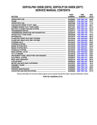
1. GDP/GLP80-120DB (D876), GDP/GLP130-160EB (D877)
SERVICE MANUAL CONTENTS
SECTION
PART
NUMBER
YRM
NUMBER
REV
DATE
OPERATOR'S CAB........................................................................................................ 524206063 0100 YRM 1100 09/08
FRAME............................................................................................................................ 524300812 0100 YRM 1349 01/11
OPERATOR'S CAB........................................................................................................ 550033400 0100 YRM 1390 11/13
CAB HEATER (PRIOR TO OCT. 2008).......................................................................... 550033397 0100 YRM 1458 04/11
CUMMINS ENGINE FAULT CODE GUIDE.................................................................... 524211827 0600 YRM 1101 07/14
MULTIPLE ALIGNED COOLING SYSTEM.................................................................... 524300813 0700 YRM 1350 05/12
TRANSMISSION REPAIR.............................................................................................. 524302733 1300 YRM 1356 03/11
TRANSMISSION OPERATION AND DIAGNOSTICS.................................................... 524304019 1300 YRM 1358 11/11
APC200 FAULT CODE GUIDE...................................................................................... 550022606 1300 YRM 1435 02/12
DIFFERENTIAL............................................................................................................... 524150779 1400 YRM 0046 08/12
PLANETARY DRIVE AXLE (WET SYSTEM)................................................................. 524150780 1400 YRM 0944 08/12
PLANETARY DRIVE AXLE (DRY SYSTEM)................................................................. 524150781 1400 YRM 0945 08/11
STEERING AXLE............................................................................................................ 524150783 1600 YRM 0326 03/07
STEERING SYSTEM...................................................................................................... 524150782 1600 YRM 0936 03/07
BRAKE SYSTEM (DRY)................................................................................................. 524150784 1800 YRM 0937 04/10
BRAKE SYSTEM (WET)................................................................................................. 524150785 1800 YRM 0951 03/11
HYDRAULIC SYSTEM.................................................................................................... 524150787 1900 YRM 0938 03/07
MAIN CONTROL VALVE................................................................................................ 524150788 2000 YRM 0943 03/07
TILT CYLINDERS........................................................................................................... 524150790 2100 YRM 0103 03/07
INSTRUMENT PANEL INDICATORS AND SENDERS................................................. 524206632 2200 YRM 1105 03/07
ELECTRICAL SYSTEM.................................................................................................. 524300814 2200 YRM 1351 04/07
MAST AND CARRIAGES............................................................................................... 524203754 4000 YRM 1062 08/12
2-STAGE MAST.............................................................................................................. 550088524 4000 YRM 1647 05/14
METRIC AND INCH (SAE) FASTENERS....................................................................... 524150797 8000 YRM 0231 10/13
ASSEMBLY GUIDE........................................................................................................ 524230692 8000 YRM 1181 12/14
DIAGRAMS..................................................................................................................... 524298462 8000 YRM 1346 05/07
PERIODIC MAINTENANCE............................................................................................ 524298463 8000 YRM 1347 09/13
CAPACITIES AND SPECIFICATIONS........................................................................... 524298464 8000 YRM 1348 07/13
Service information for Cummins diesel engines can be ordered through the Hyster Literature Distribution Center.
PART NO. 524295484 (12/14)
2. 100 YRM 1100 General
General
A fully-enclosed operators cab is positioned on four
large rubber anti-vibration mounts to isolate operator
from shock, noise, and vibration. See Figure 1. Op-
erator’s compartment includes electronic controls for
hydraulic systems, steering wheel, instrument panel,
transmission, brake system controls, and operators
seat. An overhead guard forms an integral part of the
operators cab. The cab is installed on a platform above
main frame members. Step plates on both sides of
lift truck give access to cab. The operators cab can
be tilted, providing access to major components. For
major repairs to cab, cab can be completely removed
from frame of lift truck.
1. INCHING, BRAKE, AND THROTTLE PEDALS
2. SEAT
3. STEERING COLUMN
4. FRONT, REAR, AND TOP WIPER ASSEMBLIES
5. FRONT, REAR, AND TOP WINDOWS
6. OPERATOR’S CONSOLE, CONTROLS, AND
ARMREST
7. HEATER SECTION
Figure 1. Operators Cab
1
4. 100 YRM 1100 Cab Repair
BOTTOM CAB ASSEMBLY
See Figure 3 for bottom cab assembly.
1. WIPER MOTOR
ASSEMBLY
2. WIPER COUPLING
3. AIR FILTER
4. COVER PLATE
5. STEERING PUMP
6. HORN
Figure 3. Bottom Cab Assembly
RAISING AND LOWERING CAB
Raise Cab
WARNING
Make sure no one is under cab when raising or low-
ering cab.
WARNING
Before you place any part of your body under cab,
always make sure that cab is fully tilted, or when
partially open, is locked by tilt latch.
CAUTION
Cab damage may occur if mast is not completely
tilted forward.
1. Tilt mast fully forward.
2. Remove all unsecured items from cab.
3. Close and securely latch both cab doors.
4. Clear all obstacles from right-hand side (as seen
from driver’s position) of truck. Provide minimum of
2 m (7 ft) of clearance space.
5. Use pump lever to turn direction valve clockwise to
"Raise" position. See Figure 4.
1. PUMP LEVER CONNECTION
2. DIRECTION VALVE SELECTION: CLOCKWISE -
RAISE, COUNTERCLOCKWISE - LOWER
Figure 4. Pump and Direction Valve
6. Operate pump with pump lever until cab locks in
partially open position.
NOTE: Just before fully open position is reached, move-
ment may be gravity controlled.
7. Pull tilt latch release and continue to raise cab to
fully open position. See Figure 5.
NOTE: If cab will not fully raise, lower cab until cab locks
in partially open position, and fill tilt system with oil. See
Oil Filling for Tilt System.
NOTE: Raising cab gives access to components such
as engine, transmission/hydraulic compartment, throt-
tle/brake and steering control, heater, air conditioner,
and electrical connectors.
3
5. Cab Repair 100 YRM 1100
1. CAB
2. FRAME
3. TILT LATCH RELEASE
4. PUMP LEVER
Figure 5. Pump Lever and Tilt Latch Release Knob
Lower Cab
WARNING
Make sure no one is under cab when raising or low-
ering cab.
WARNING
Before you place any part of your body under cab,
always make sure that cab is fully tilted, or when
partially open, is locked by tilt latch.
CAUTION
Cab damage may occur if mast is not completely
tilted forward.
1. Use pump lever to turn direction valve counterclock-
wise to "Lower" position. See Figure 4.
2. Check that all foreign items/tools are cleared away.
3. Operate pump with pump lever until cab locks in
partially open position.
4. Pull tilt latch release and continue to lower cab until
it is in fully lowered position and latched. See Fig-
ure 5.
NOTE: An electric-powered cab tilt system is available
to replace standard manual tilt system. The electric tilt
system contains a push button located on left side of
pump direction control. Procedure to raise or lower is
the same.
CAB REPAIR
Remove
WARNING
Before removing heater hoses, allow time for heater
hoses to cool down. Hot water may cause severe
burns.
WARNING
Make sure the lifting device has a minimum capac-
ity to lift 1000 kg (2205 lb). A lifting device that does
not have the minimum capacity can break causing
the cab to drop and may result in serious personal
injury.
CAUTION
Lift the operator’s cab carefully. Make sure all wires
and attachments are disconnected and loose com-
ponents are not obstructing the movement.
1. Switch off engine.
2. Disconnect battery ground lead.
3. Raise operator’s cab. See Raise Cab.
4. Remove four hex bolts holding steering pump. See
Figure 6.
5. Remove two bolts holding brake valve.
6. Disconnect electrical cable to throttle pedal sensor.
See Figure 11.
7. Disconnect electrical cable.
8. Disconnect electrical plugs that are located to right
of heater unit.
9. Disconnect window washer hoses and mark their
positions.
10. Remove three bolts and swing heater unit down.
11. Disconnect electrical connections, control cables,
and air duct from heater unit.
12. Disconnect ground lead.
4
6. 100 YRM 1100 Cab Repair
1. STEERING PUMP HEX BOLTS
2. BRAKE VALVE BOLTS
3. STEERING PUMP
4. BRAKE VALVE
5. ELECTRICAL CONNECTIONS
Figure 6. Steering Pump, Throttle and Inching
Connections
CAUTION
When lowering cab, make sure loose components
are not obstructing the movement.
13. Lower operator’s cab. See Lower Cab.
14. Remove left and right side panels giving access to
cab mounting bolts.
15. Remove four mounting bolts, two on left side and
two on right side of truck.
16. Remove cab doors before attaching a lifting device.
17. Connect a lift strap under overhead guard structure.
Provide a cushion at top of door area to prevent
damage.
18. Carefully lift cab away from lift truck. Set cab as-
sembly in a suitable storage area and put blocks
under cab to stabilize and prevent damage.
19. Remove four rubber isolation mounts from frame
and inspect for damage. Reinstall or replace if nec-
essary.
Install
1. Connect lift strap under overhead guard structure.
Provide cushion at top of door area to prevent dam-
age.
2. Make sure that insulators are in place. See Fig-
ure 7.
1. TOP PART OF INSULATOR
2. BOTTOM PART OF INSULATOR
3. BOLT
4. WASHER
5. LOCKWASHER
Figure 7. Insulators
3. Lift operator’s cab.
4. Carefully lower cab on insulators and make sure
that it is properly centered.
5. Mount cab with washers and bolts.
6. Tighten cab mounting bolts to 66 N•m (49 lbf ft).
7. Raise cab. See Raise Cab.
8. Connect electrical cables, ground wire, hoses,
steering pump, and brake valve. Make sure that all
connections have been restored.
9. Mount heater unit to hinge. Connect control cables
and electrical connections. Pivot unit up and install
with three bolts.
10. Connect inching and throttle cables. See Inching
and Brake Pedals.
5
7. Oil Filling for Tilt System 100 YRM 1100
11. Lower cab. See Lower Cab.
12. Install doors.
13. Connect battery ground lead.
14. Install side panels.
Oil Filling for Tilt System
CAUTION
When oil has been added, put oil-absorbing mate-
rial around filler plug before lowering cab. Excess
oil may bleed out of relief valve, which is fitted in
filler plug.
NOTE: When cab does not reach the maximum opening
the oil level is low.
1. Lower cab until it locks in partially open position.
See Lower Cab.
2. Put pump lever connection in fully down position to
gain access to the fill cap. See Figure 8.
3. Remove fill cap. See Figure 8.
4. Add hydraulic oil into filler opening until level is
within 30 to 35 mm (1.18 to 1.38 in.) of top of
reservoir. See Figure 9.
5. Install fill cap. See Figure 8.
6. Raise cab and make sure that maximum tilt can be
reached. See Raise Cab.
7. Repeat procedure if necessary.
8. Lower cab until it is in fully lowered position and
completely latched.
1. FILL CAP
Figure 8. Hand Pump
Figure 9. Cab Tilt Label
6
8. 100 YRM 1100 Inching and Brake Pedals
Inching and Brake Pedals
BRAKE PEDAL, ADJUST
1. Adjust bolt (3), behind the brake pedal, on the brake
pedal assembly so that the roller has contact with
the bolt on the valve until there is no free travel. See
Figure 10.
1. BRAKE PEDAL
2. INCHING PEDAL
3. ADJUSTMENT BOLT FOR BRAKE PEDAL
4. ADJUSTMENT BOLT FOR INCHING/BRAKE
PEDAL COUPLING
5. ADJUSTMENT BOLT FOR INCHING PEDAL
Figure 10. Brake Pedal System
2. Proceed with inching pedal adjustment.
INCHING PEDAL, ADJUST
NOTE: Adjust the inching pedal so that the brake pedal
moves at the same time, which means there is no free
play with the brake pedal.
NOTE: When brake pedal and inching pedal are in re-
leased position their position must be equally high or in
line.
1. When activating inching pedal, brake pedal should
be activated as soon as top of inching pedal and
top of brake pedal are on same plane. Use adjust-
ment bolt (4) for inching/brake pedal coupling ad-
justment. See Figure 10.
2. Adjust bolt (5) for inching pedal to eliminate free
travel of inching pedal before braking action occurs.
3. Proceed with inching pedal sensor adjustment.
INCHING PEDAL SENSOR, ADJUST
NOTE: When the brake pedals are not activated, the
analog output of the inch sensor should be between 600
and 700 mV. This means the sensor is slightly turned as
the lowest possible reading is 400 mV.
1. Loosen the two, one shown, sensor mounting bolts.
See Figure 11.
NOTE: To read the voltage, use the "Inching Pedal Cal-
ibration" mode of the Userlink®
program as explained in
the section Transmission 1300 YRM 1082.
2. Rotate sensor in the slotted holes underneath the
inching pedal so that the output voltage of the sen-
sor of the released inching pedal is between 600
and 700 mV.
3. Tighten the mounting screws and recheck the volt-
age output at the sensor.
4. Calibrate the inching pedal. See the section Trans-
mission 1300 YRM 1082.
1. MOUNTING BOLT
Figure 11. Sensor Adjustment
7
9. Throttle Pedal Sensor 100 YRM 1100
Throttle Pedal Sensor
CHECK
NOTE: When a new throttle pedal sensor is installed,
rotate the throttle pedal sensor counterclockwise, when
looking inside the throttle box, until the end of the slotted
holes. See Figure 12.
1. Switch engine ON.
2. Operate throttle pedal. See Figure 12.
3. Check position, dimension A, of the throttle pedal at
which the engine rpm goes from idle to higher rpm
value.
4. If dimension A is not within 6 to 10 mm (0.236 to
0.394 in.), adjust the mechanical position of the
electronic throttle potentiometer. See Adjust.
ADJUST
1. Raise cab. See Raise Cab.
2. Make sure the throttle pedal stop is adjusted so that
it is against the cabin floor plate.
3. Position a 5 mm (0.197 in.) spacer between the
throttle pedal and throttle pedal stop.
4. Loosen mounting screws and turn the throttle pedal
sensor to position at which engine rpm increases
from idle or decreases rpm to idle.
5. Tighten mounting screws.
6. Remove the 5 mm (0.197 in.) spacer between the
throttle pedal and throttle pedal stop.
7. Lower cab. See Lower Cab.
1. DIMENSION A
2. THROTTLE PEDAL
3. THROTTLE PEDAL ADJUSTMENT
4. THROTTLE PEDAL SENSOR
5. MOUNTING SCREW
6. COUPLING
7. CABIN FLOOR PLATE
8. THROTTLE PEDAL STOP
9. COUNTERCLOCKWISE
10. SLOTTED HOLE
Figure 12. Throttle Arrangement
8
10. 100 YRM 1100 Power Assist Armrest
Seat Assembly Removal
NOTE: Use a lifting device for removal of seat.
NOTE: For mechanical seat, there will be one connec-
tor. For air suspension seat, there will be two connec-
tors.
1. Disconnect battery ground lead.
2. Disconnect connector(s). See Figure 13.
3. Disconnect plug to side console.
4. Loosen four bolts connecting seat to cab.
5. Remove seat.
Legend for Figure 13
1. ELECTRICAL CONNECTORS AND PLUG TO
SIDE CONSOLE (REAR OF SEAT)
2. BOLTS
Figure 13. Operators Seat
Power Assist Armrest
ADJUST
1. Disconnect cable from lever. See Figure 14.
2. Remove the mounting bolts that hold the gas spring
assembly.
3. Loosen nut.
4. Adjust top section, clockwise or counterclockwise,
to obtain a free lever movement of 1.5 to 2.0 mm
(0.06 to 0.079 in.).
NOTE: Apply small bead of non permanent Loctite®
to
bolt treads.
5. Install gas spring assembly using the two bolts.
6. Install and adjust cable on lever to obtain correct
operation.
Legend for Figure 14
1. LEVER
2. TOP SECTION
3. NUT
4. BOLT
5. LEVER
6. CABLE
Figure 14. Power Assist Armrest
9
11. Thank you very much for
your reading. Please Click
Here. Then Get COMPLETE
MANUAL. NO WAITING
NOTE:
If there is no response to
click on the link above,
please download the PDF
document first and then
click on it.
12. Steering Column Repair 100 YRM 1100
Steering Column Repair
REMOVE
1. Raise cab. See Raise Cab.
2. Disconnect battery ground lead.
3. Disconnect steering column connector. See Fig-
ure 15 and Figure 16.
4. Remove four hex bolts fastening steering pump to
cab and carefully remove steering pump.
5. Remove two cab mounting bolts holding steering
column to the floor.
6. Lower cab. See Lower Cab.
7. Remove two hex bolts holding steering column to
bracket.
8. Remove steering column. Push grommet out of
hole and slide connector through hole.
INSTALL
1. Slide connector through hole in floor and push
grommet into hole.
2. Connect steering column to bracket with two cab
mounting bolts.
3. Raise cab. See Raise Cab.
4. Mount steering column to cab base with two steer-
ing column hex bolts.
5. Carefully mount steering pump with four steering
pump hex bolts to allow non-forced coupling be-
tween steering pump and steering column.
6. Connect electrical connector.
7. Connect battery ground lead.
8. Lower cab. See Lower Cab.
1. STEERING COLUMN TO BRACKET BOLTS
2. STEERING COLUMN TO FLOOR PLATE BOLTS
Figure 15. Steering Column
1. STEERING COLUMN CONNECTOR
2. STEERING COLUMN BOLTS
3. STEERING PUMP BOLTS
Figure 16. Steering Pump
10
13. 100 YRM 1100 Window Wipers Replacement
Window Wipers Replacement
NOTE: Three window wiper motor assemblies are in-
stalled in the cab. The front window has a single-arm,
parallelogram-type, wiper motor system to give a large
wiped surface area. The wiper motor is mounted under
the cab so as not to obstruct visibility. The top window
is provided with a wiper motor assembly that has one
wiper arm with wiper blade. The rear window is pro-
vided with a wiper motor assembly that has one wiper
arm with wiper blade. A washer system is connected to
all wipers.
WINDOW WIPER ASSEMBLY, REPLACE
1. Lift cover. See Figure 17.
2. Loosen and remove nut and washer.
3. Mark position of blade on window.
4. Disconnect wiper.
5. Disconnect washer hose if applicable.
6. Install new wiper assembly. Make sure that wiper
assembly is properly positioned to give optimal cov-
erage of window. Proceed in reverse order.
1. COVER
2. COVER OPEN
3. NUT WITH
WASHER
Figure 17. Wiper Assembly
FRONT WINDOW WIPER MOTOR
ASSEMBLY, REPLACE
1. Disconnect battery ground lead.
2. Disconnect connector. See Figure 18.
3. Remove clamp tightening bolt and arm.
4. Remove three bolts.
5. Remove motor assembly.
6. Install new motor assembly. Proceed in reverse or-
der.
1. CLAMP TIGHTENING BOLT AND ARM
2. BOLTS
3. MOTOR ASSEMBLY
4. CONNECTOR
Figure 18. Front Window Wiper Motor Assembly
11
14. Window Wipers Replacement 100 YRM 1100
REAR WINDOW WIPER MOTOR
ASSEMBLY, REPLACE
1. Disconnect battery ground lead.
2. Remove wiper assembly. See Window Wiper As-
sembly, Replace.
3. Remove cover of motor assembly unit.
4. Disconnect connector. See Figure 19.
5. Remove nuts and washers.
6. Remove motor assembly.
7. Install new motor assembly. Proceed in reverse or-
der.
1. CONNECTOR
2. NUTS AND WASHERS
Figure 19. Rear Wiper Motor Assembly
TOP WINDOW WIPER MOTOR ASSEMBLY,
REPLACE
1. Disconnect battery ground lead.
2. Remove 10 screws fastening headliner to cab. See
Figure 20.
3. Remove headliner.
4. Follow procedure as listed under Rear Window
Wiper Motor Assembly, Replace.
5. Replace cab headliner.
6. Connect battery ground lead.
1. SCREWS
Figure 20. Cab Headliner
12
15. 100 YRM 1100 Window Washer Motors and Pumps
Window Washer Motors and Pumps
NOTE: Three window washer motors with pump as-
semblies are attached to a water reservoir. See Fig-
ure 21.
NOTE: When replacing washer motor(s), make sure
that water hose(s) is connected to proper pump(s).
1. FRONT WINDOW WASHER MOTOR AND PUMP
2. TOP WINDOW WASHER MOTOR AND PUMP
3. REAR WINDOW WASHER MOTOR AND PUMP
Figure 21. Washer Motors and Pumps
WINDOW WIPER AND WASHER
OPERATING SWITCHES
NOTE: The switch panel for the front, top, and rear win-
dow wipers and washers is located on the side of the
operators arm rest/console. See Figure 22.
NOTE: The fuses, protecting wiper, and washer sys-
tems are located inside the operators compartment.
See Fuse Panel.
1. FRONT WINDOW WIPER
2. TOP WINDOW WIPER AND WASHER
3. REAR WINDOW WIPER AND WASHER
4. FRONT WINDOW WASHER
Figure 22. Wiper and Washer Switches
13