Downloaded 918 times
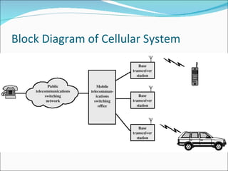
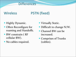
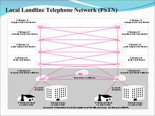
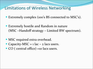
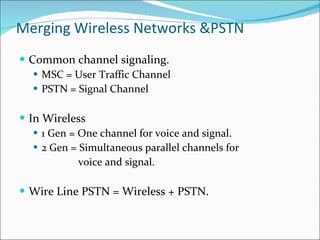
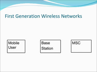
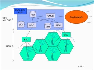
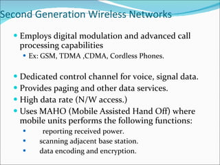
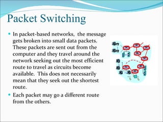
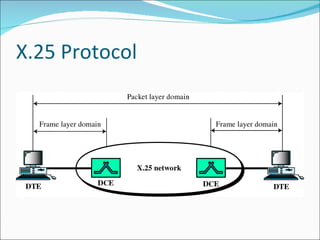
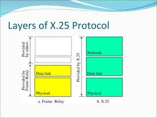

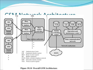
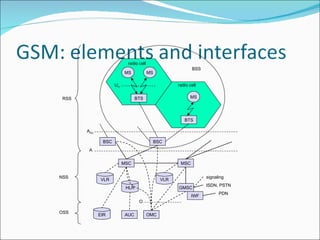
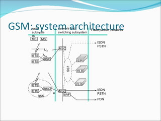


The document provides information on the evolution of wireless networks from 1G to 3G. It discusses the key components and architecture of cellular systems including base stations, mobile switching centers and their connection to the public switched telephone network. It also compares the differences between wireless and wired networks, and describes some of the limitations of early wireless networking. Finally, it covers topics like traffic routing, circuit switching, packet switching and the X.25 protocol.


![RF Circuit Design - [Ch4-2] LNA, PA, and Broadband Amplifier](https://cdn.slidesharecdn.com/ss_thumbnails/ch4-2-150613064410-lva1-app6891-thumbnail.jpg?width=640&height=640&fit=bounds)


![Gprs[1]](https://cdn.slidesharecdn.com/ss_thumbnails/gprs1-170504135214-thumbnail.jpg?width=640&height=640&fit=bounds)


