
Download as PDF, PPTX

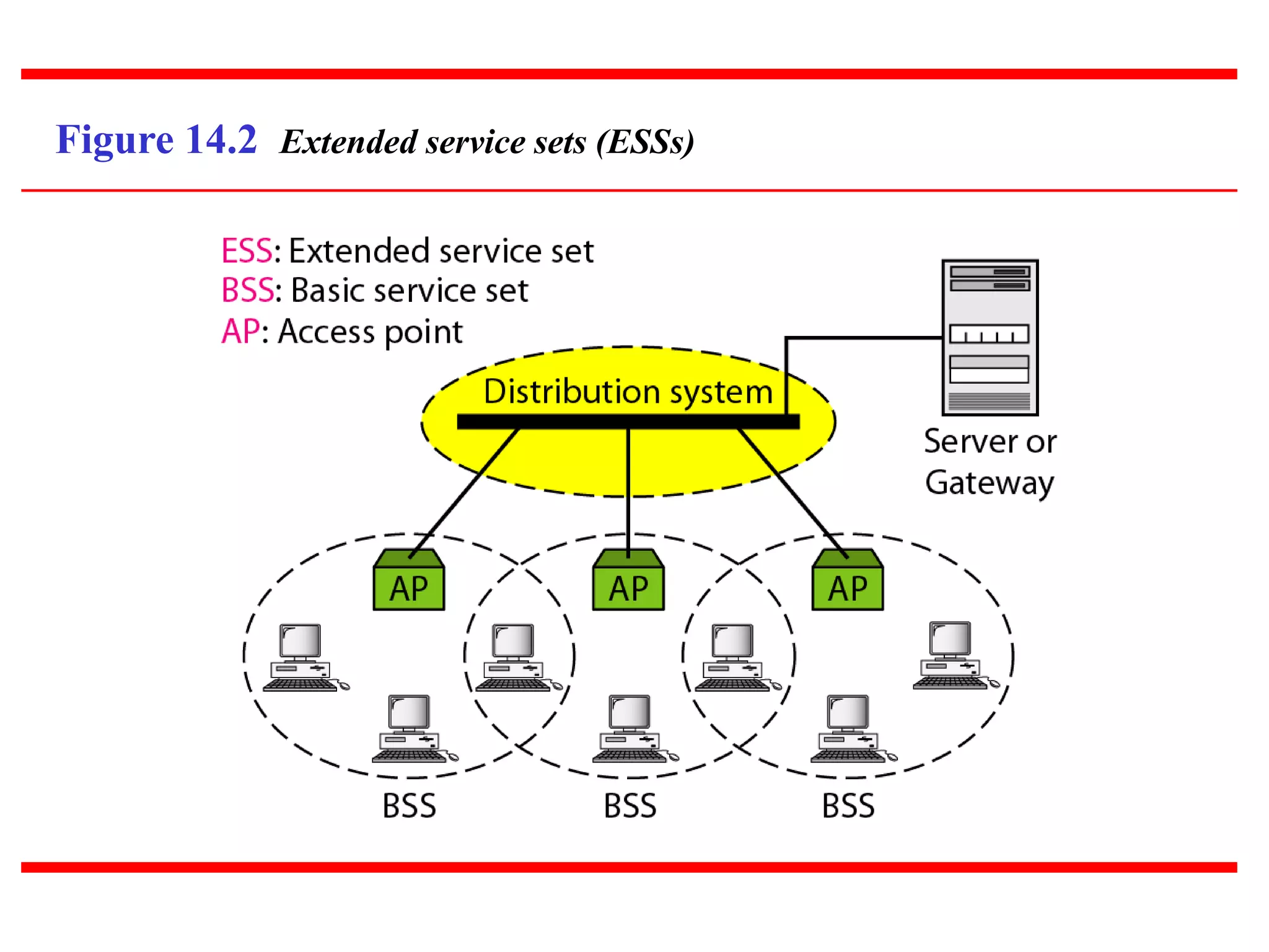
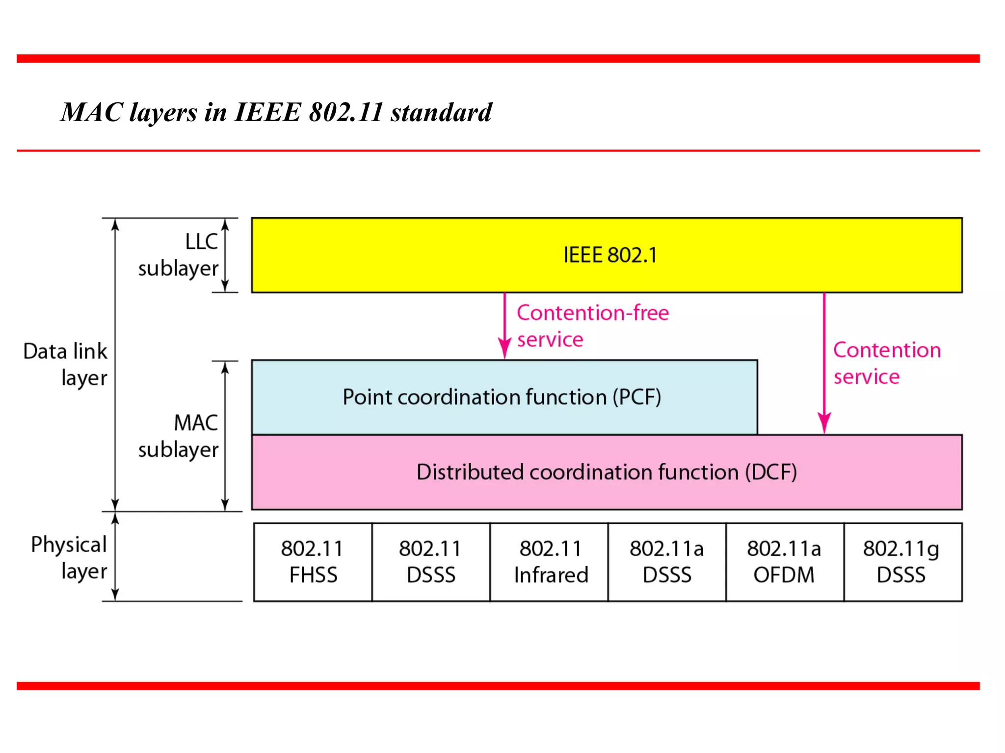
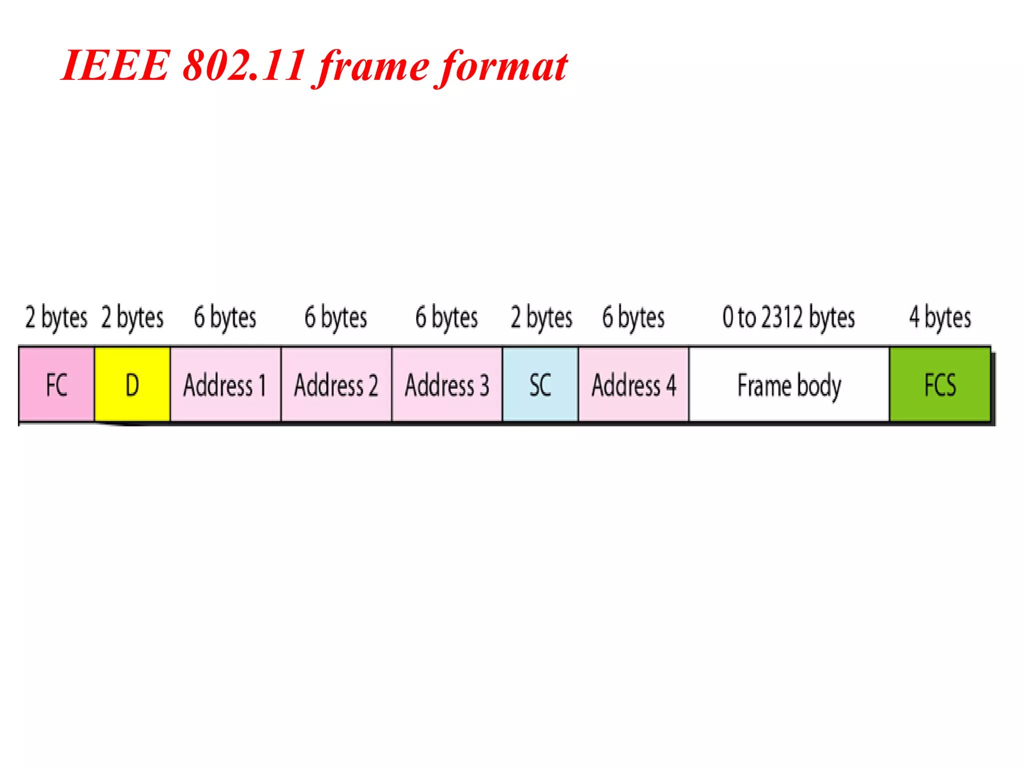
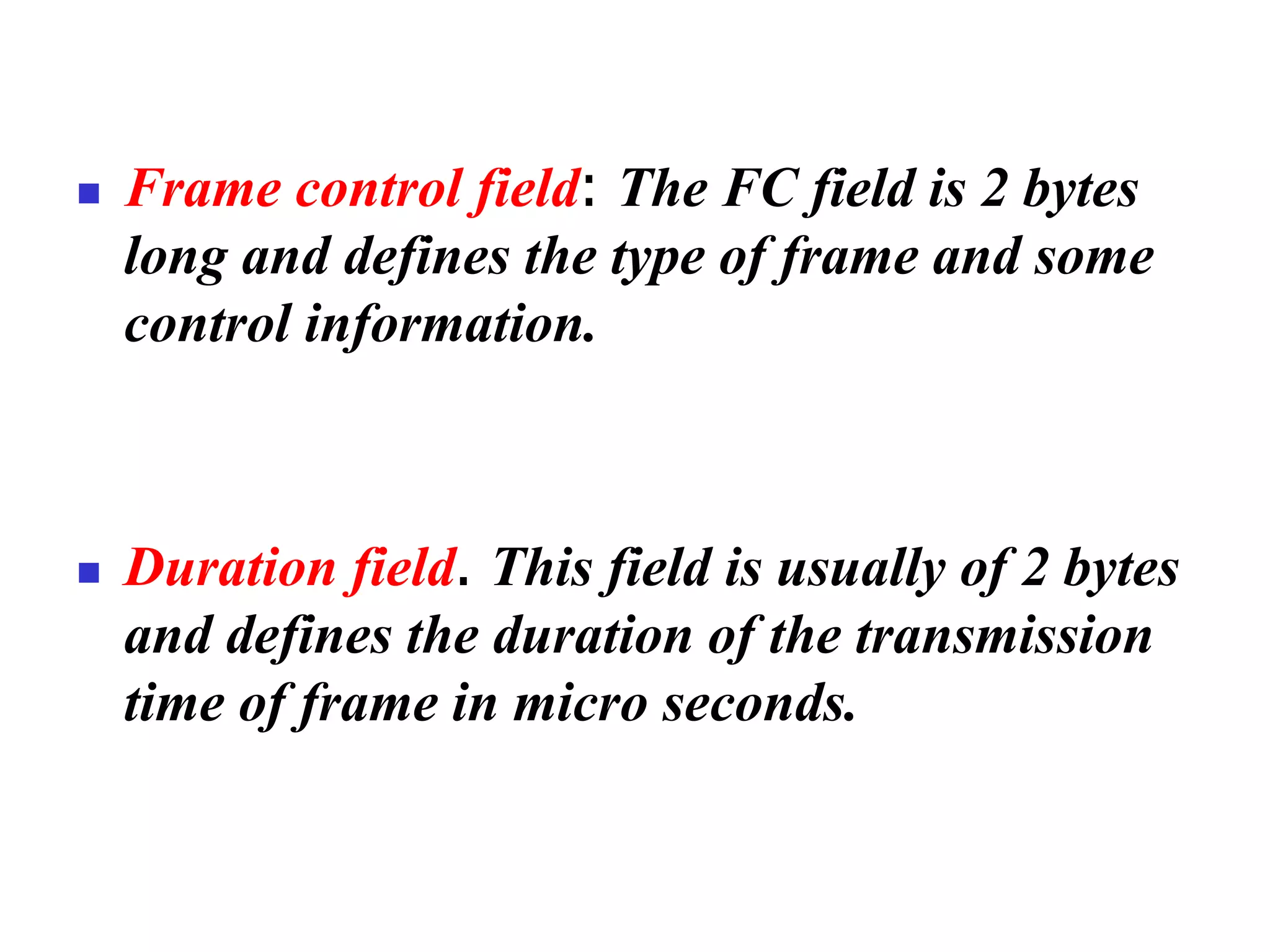

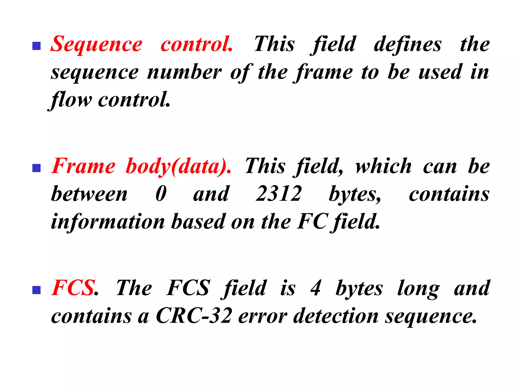
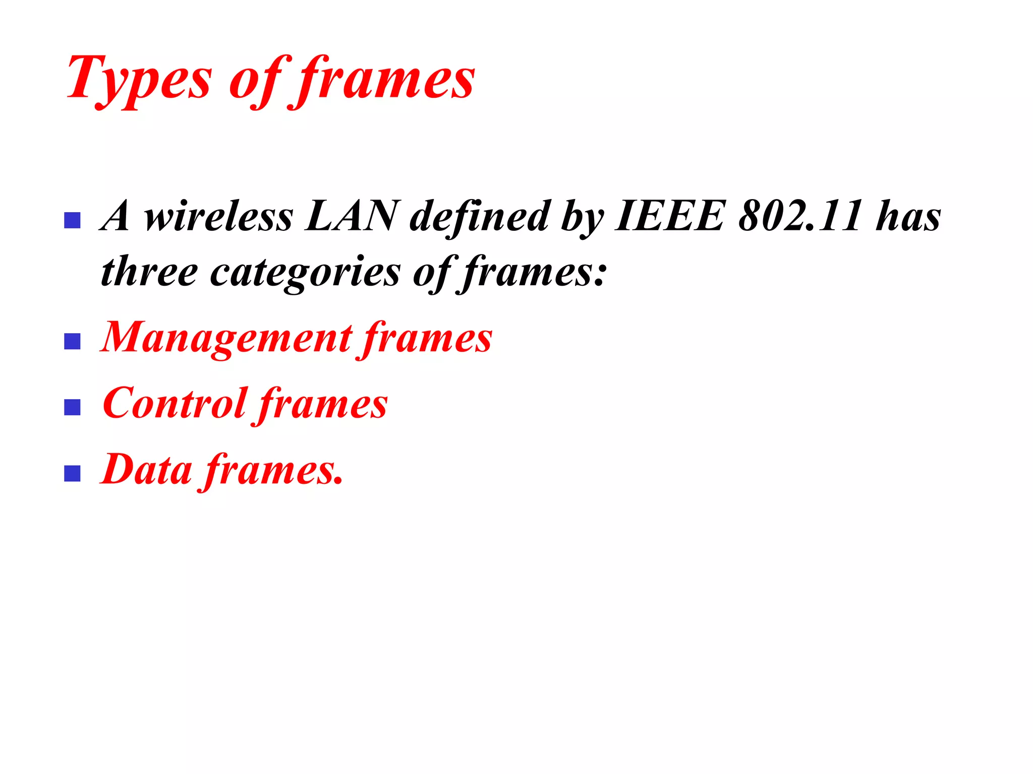
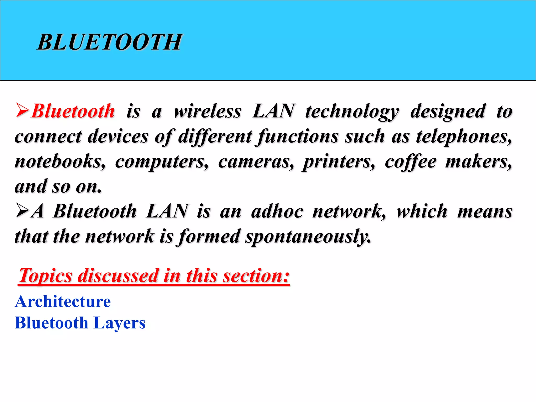
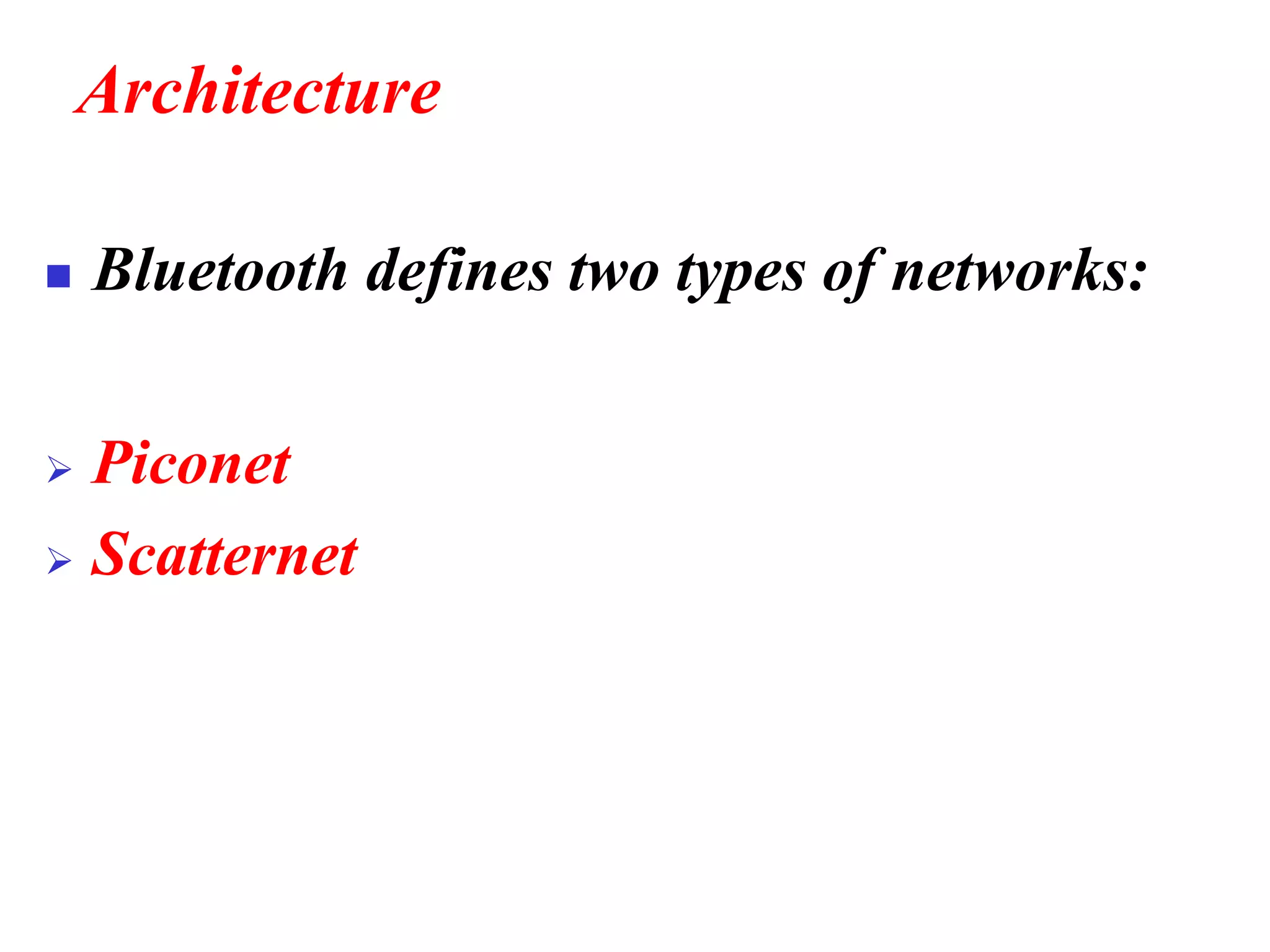
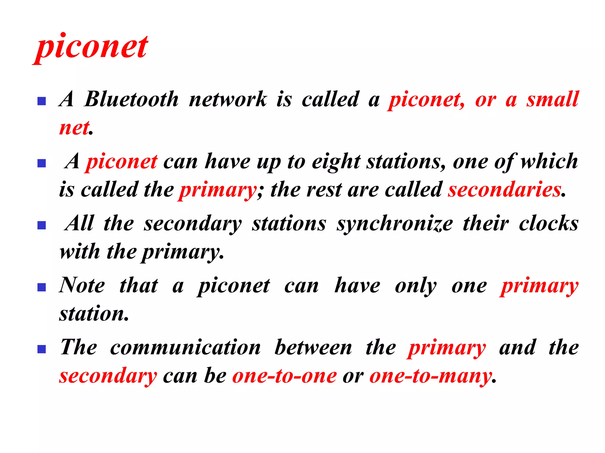
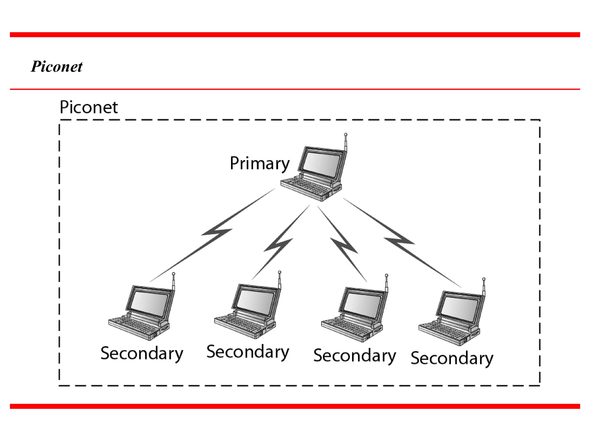
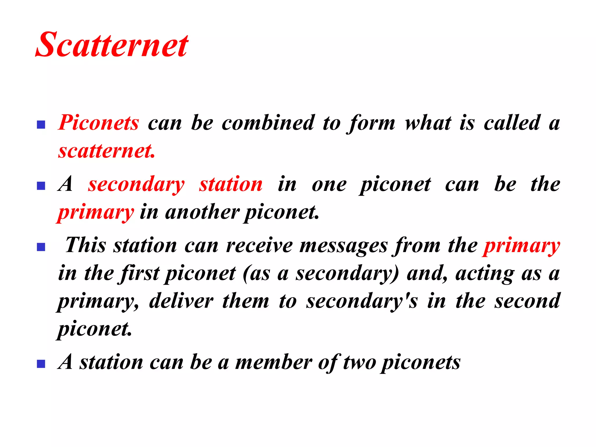
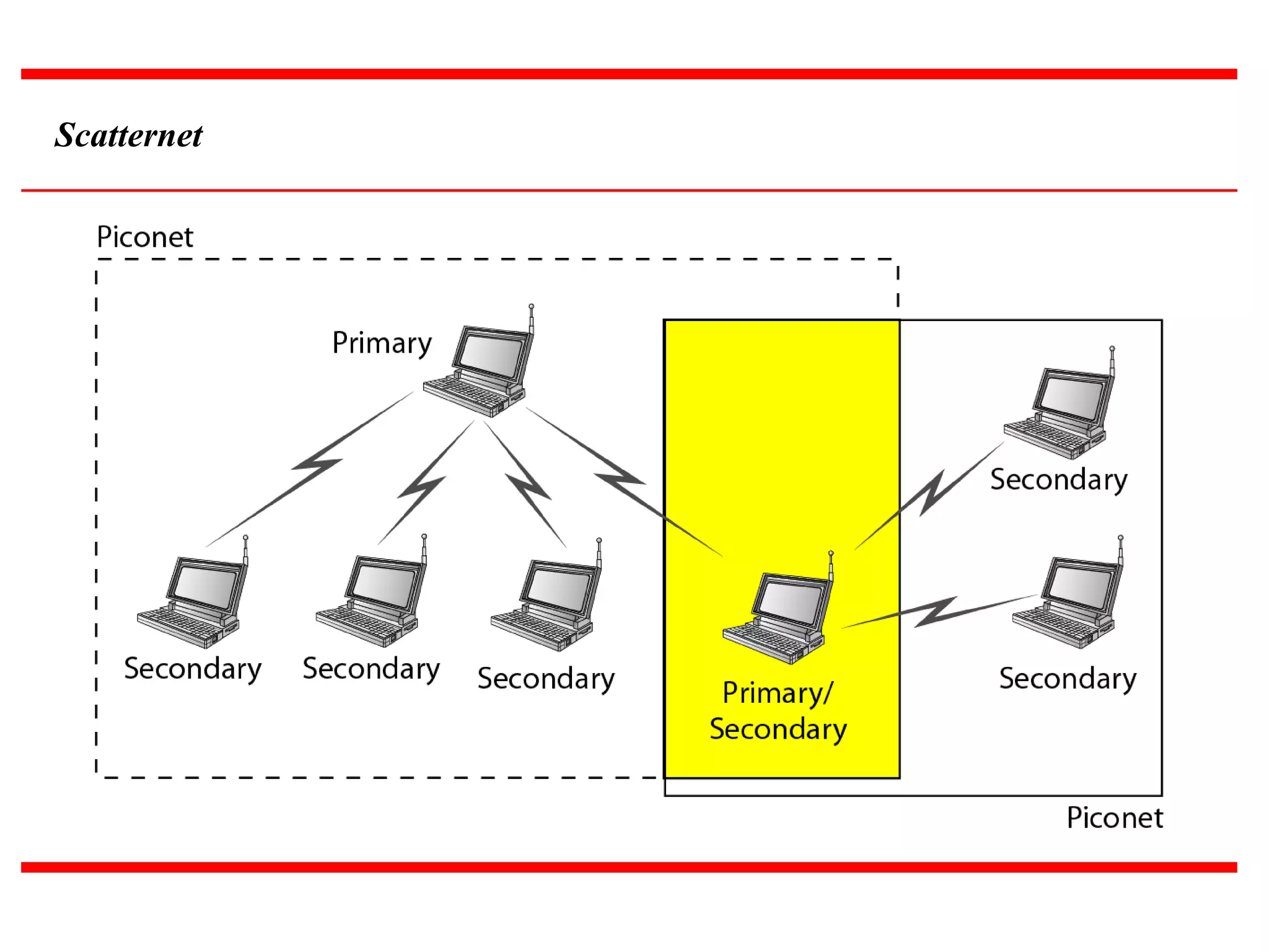


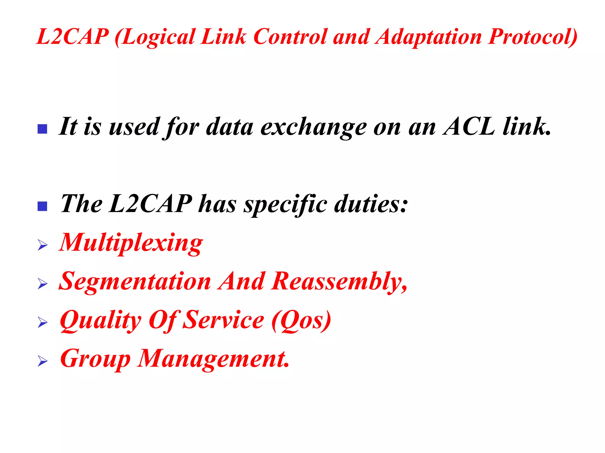
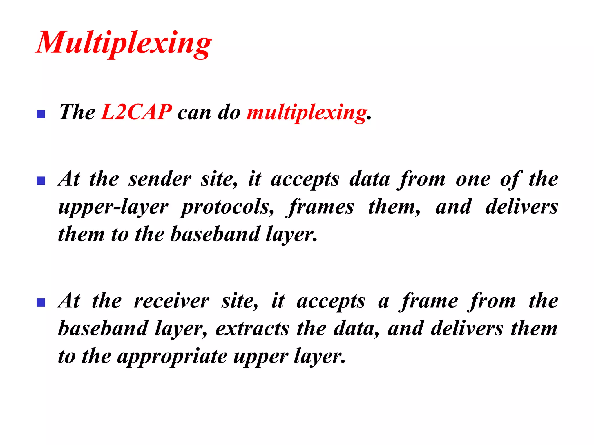
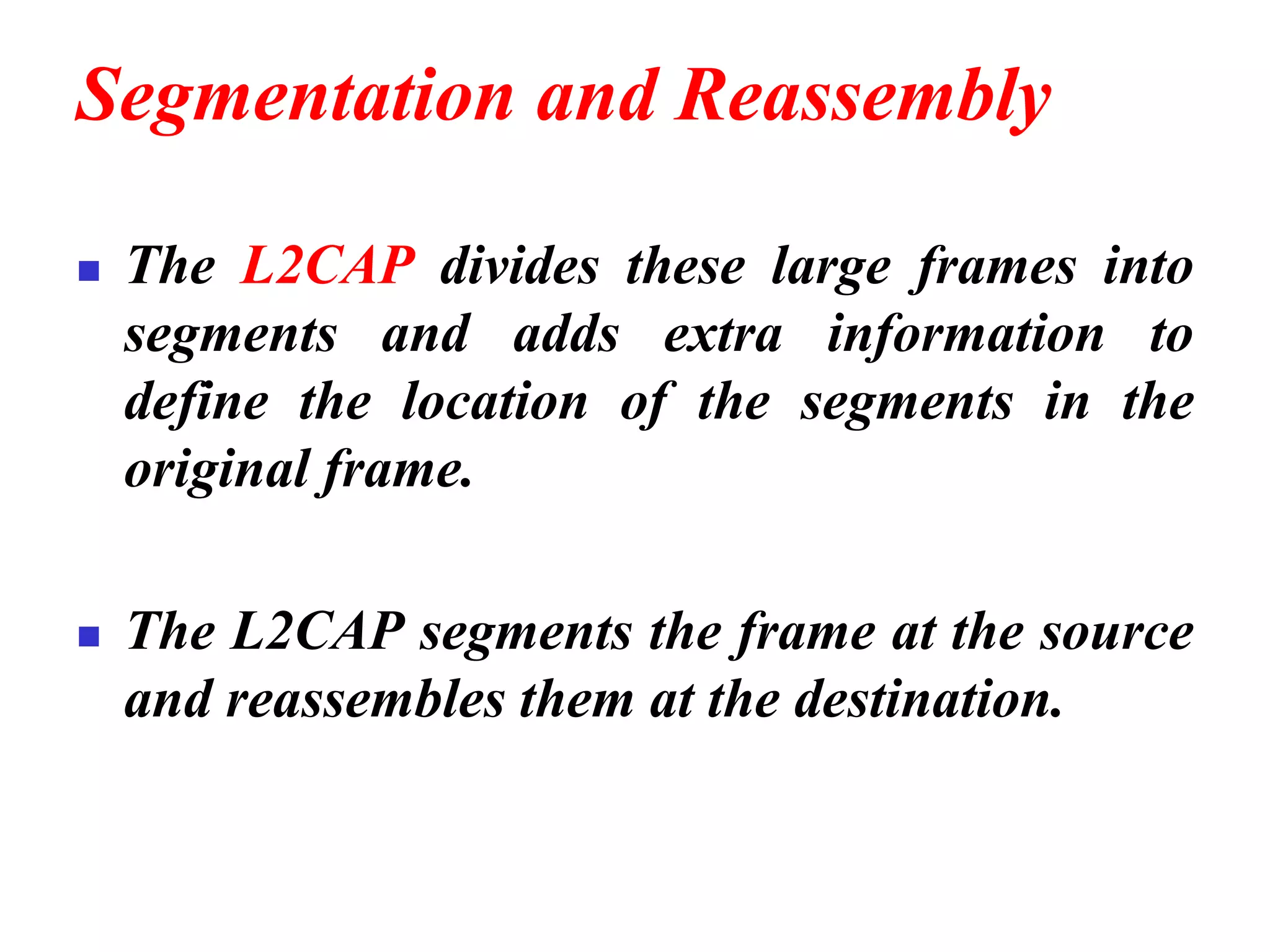
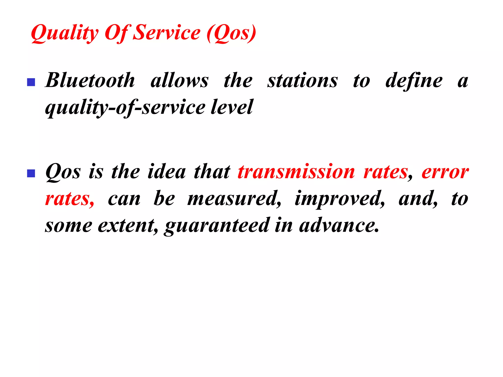
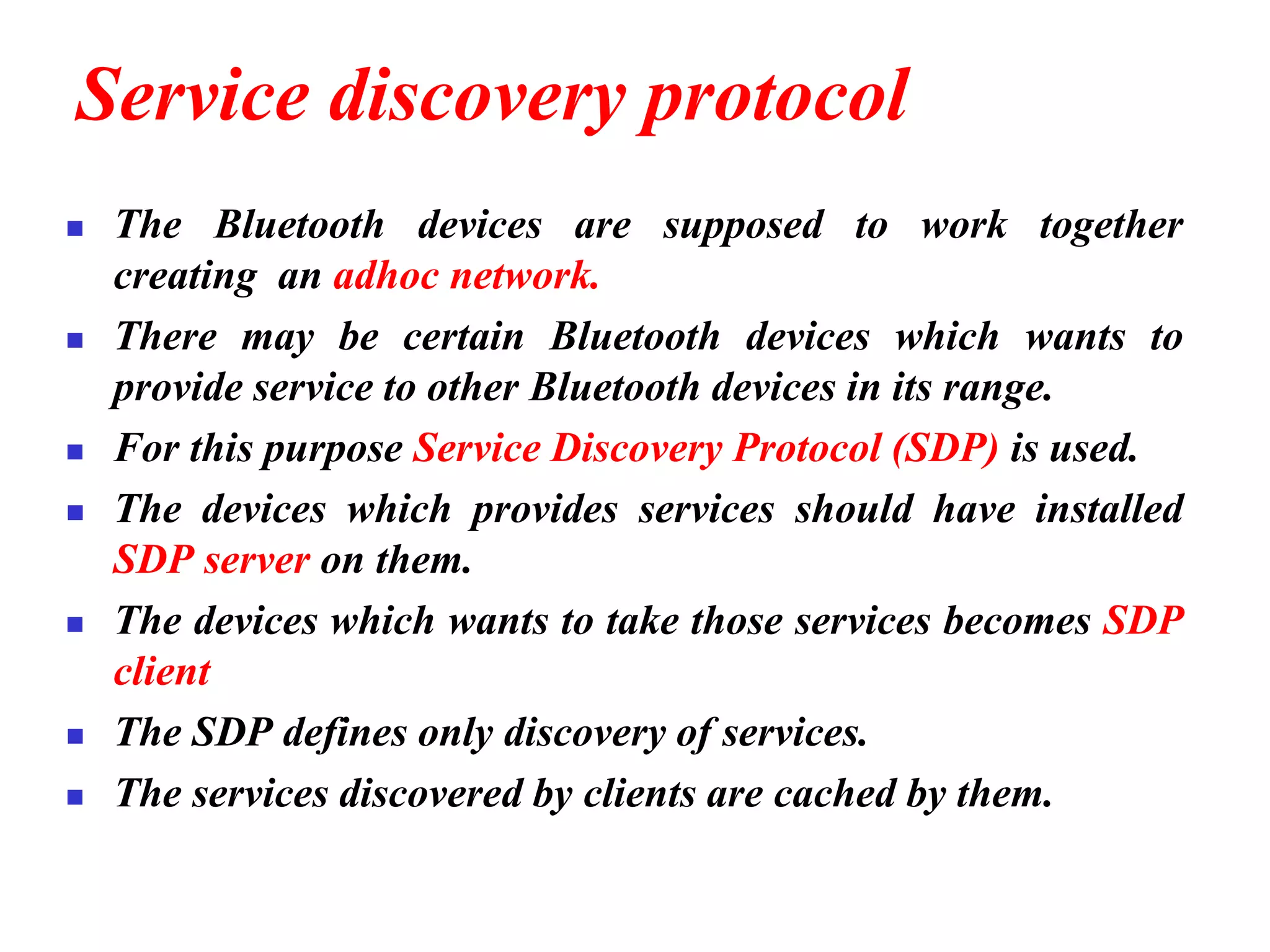
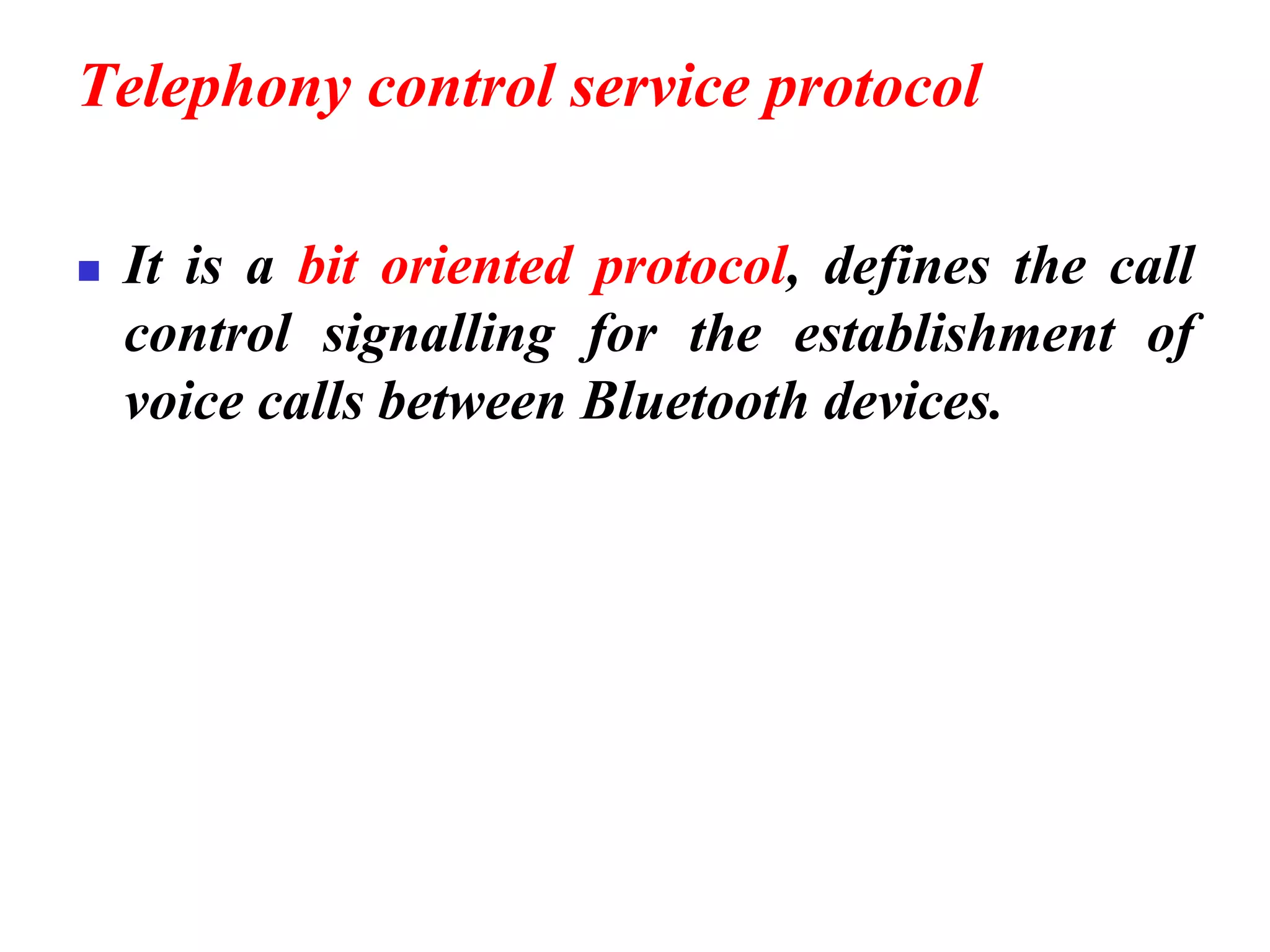
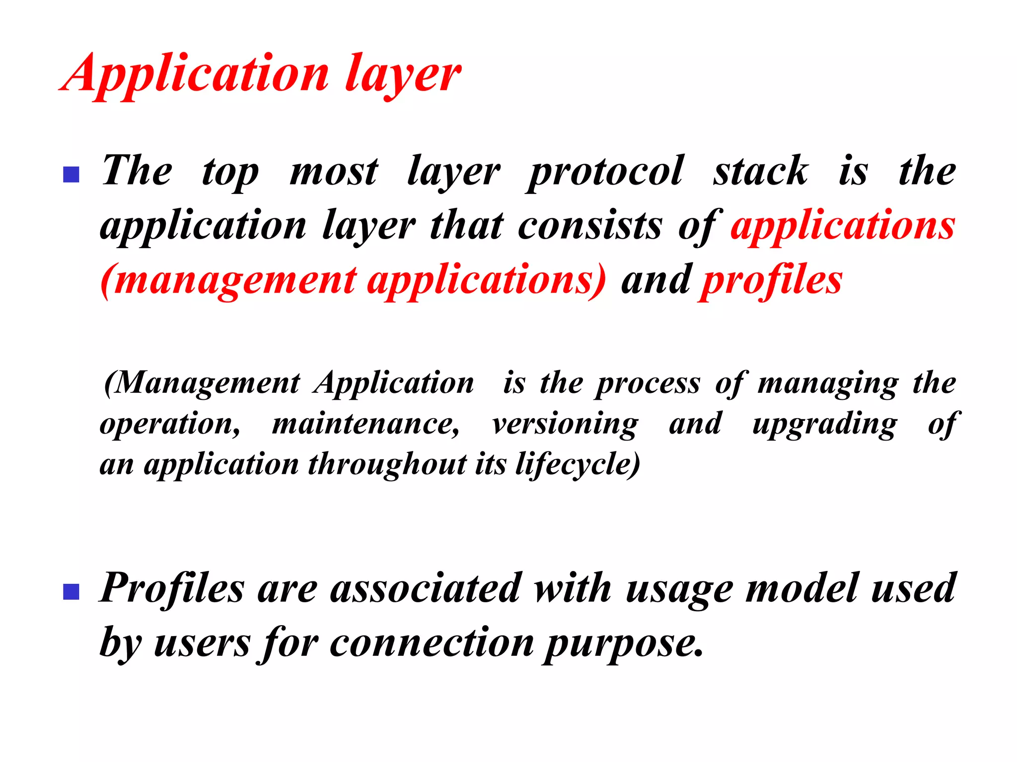
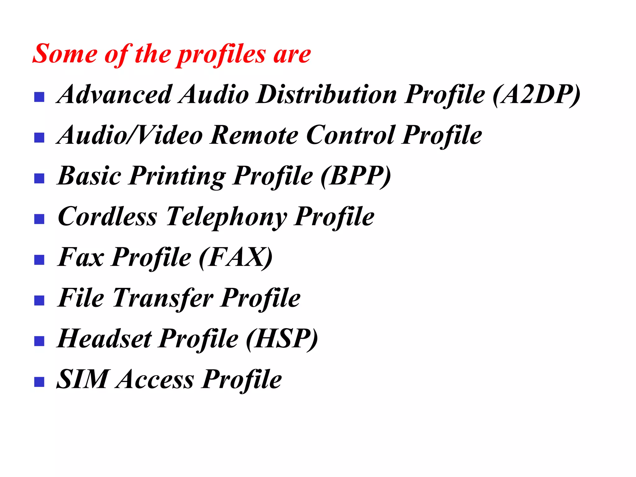

The document discusses wireless LAN technologies, focusing on IEEE 802.11 and Bluetooth. It explains the architecture of wireless LANs, including basic and extended service sets, as well as the MAC sublayers and frame formats. Additionally, it details Bluetooth networking, including piconets and scatternets, and describes various layers and protocols within Bluetooth technology.


![Coded Agents – with UiPath SDK + LangGraph [Virtual Hands-on Workshop]](https://cdn.slidesharecdn.com/ss_thumbnails/codedagentsdeck-251215155422-5497c599-thumbnail.jpg?width=640&height=640&fit=bounds)


