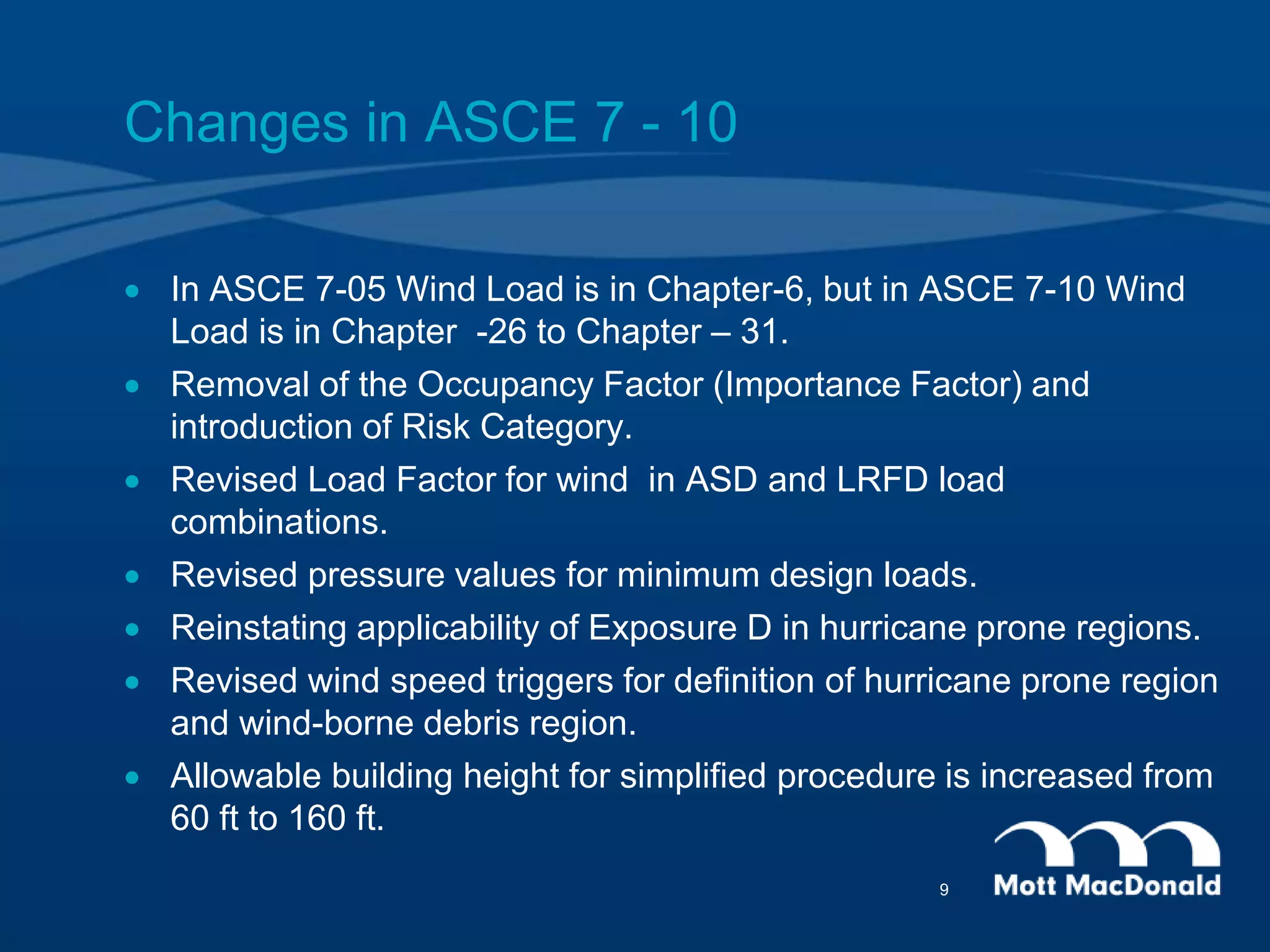
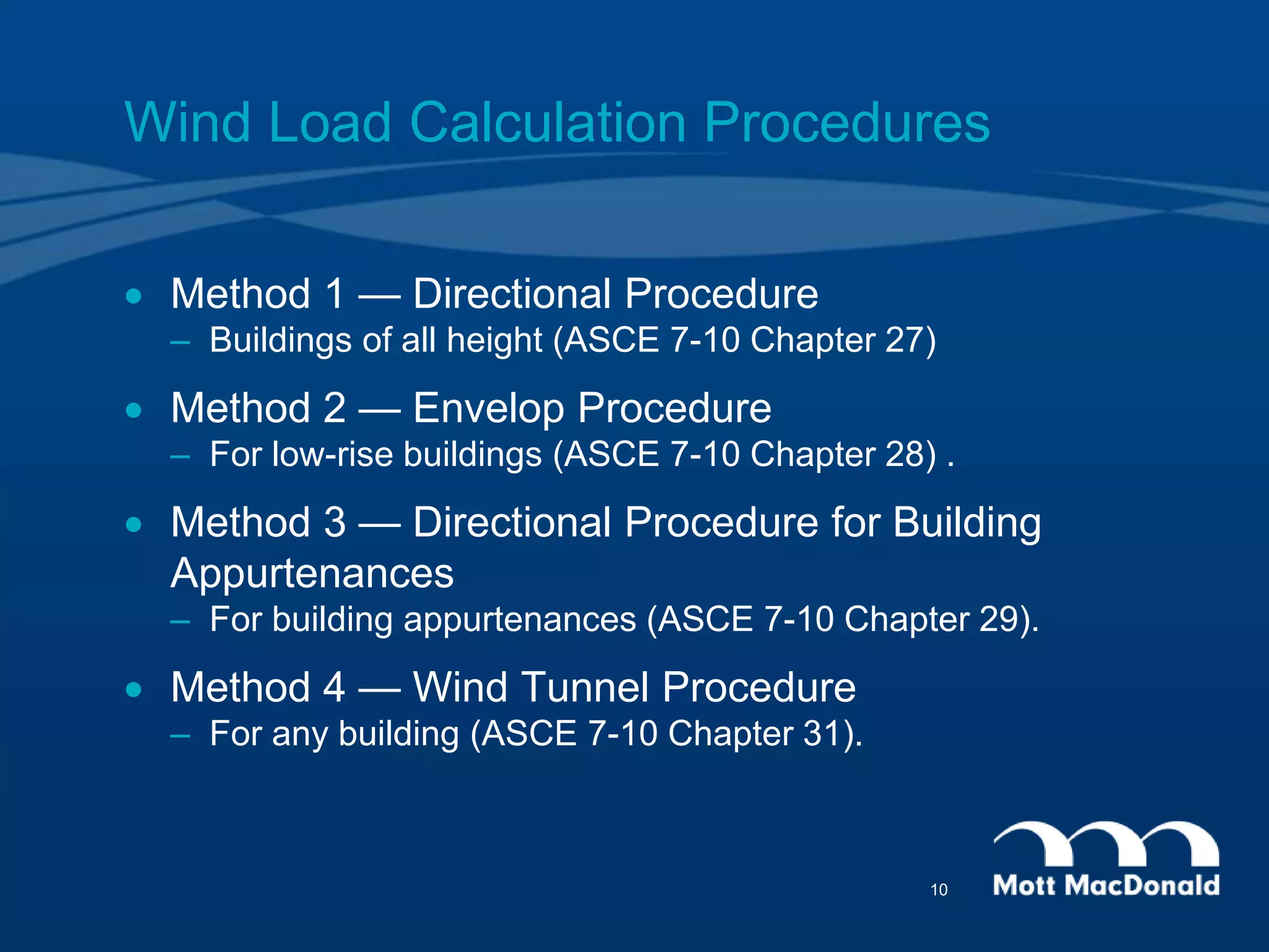
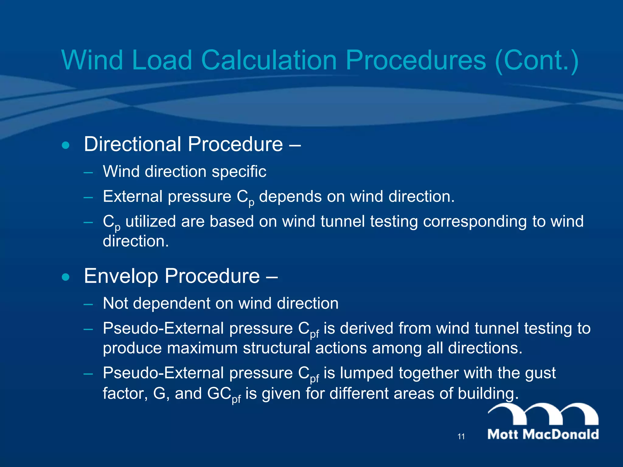
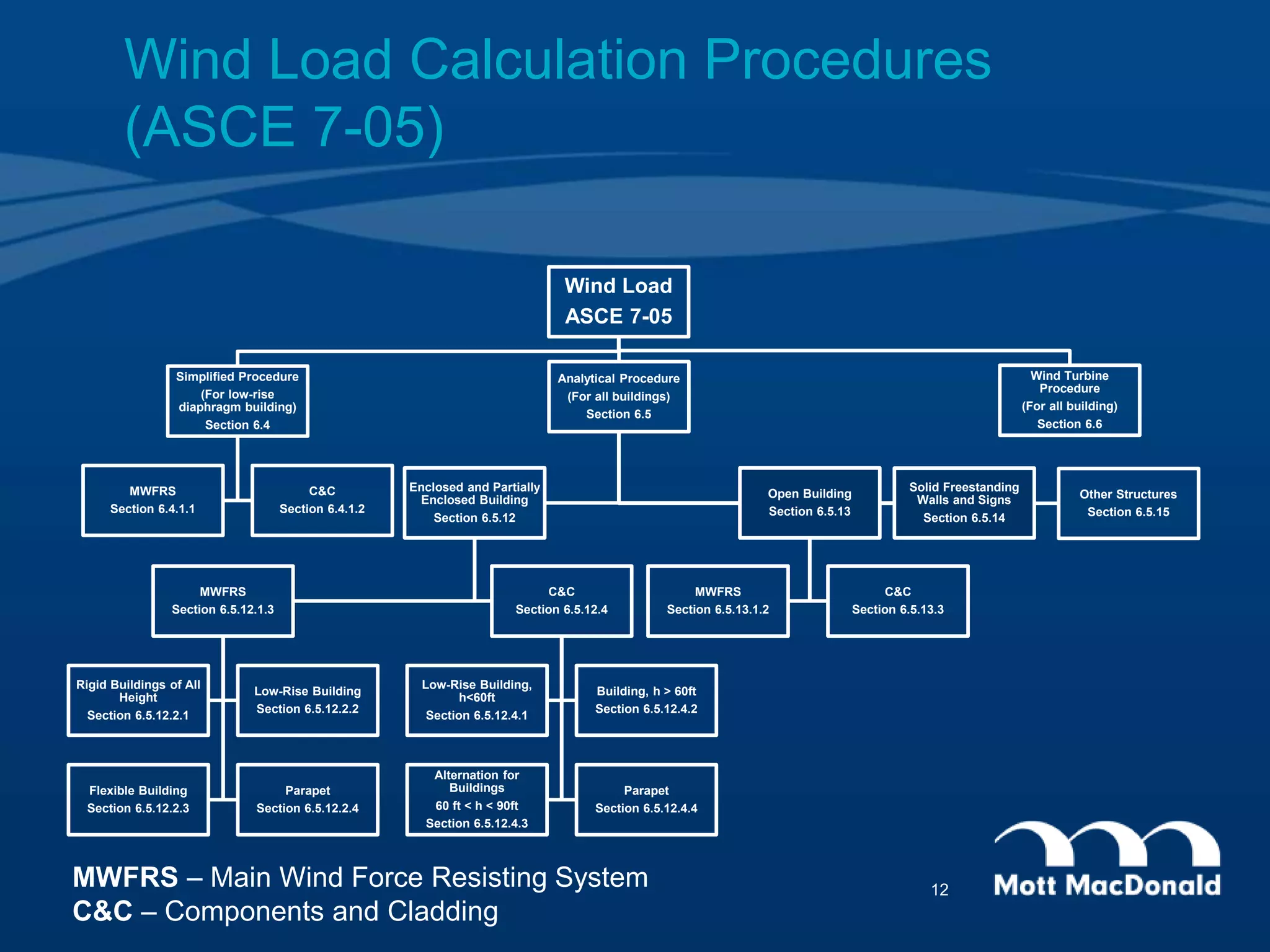
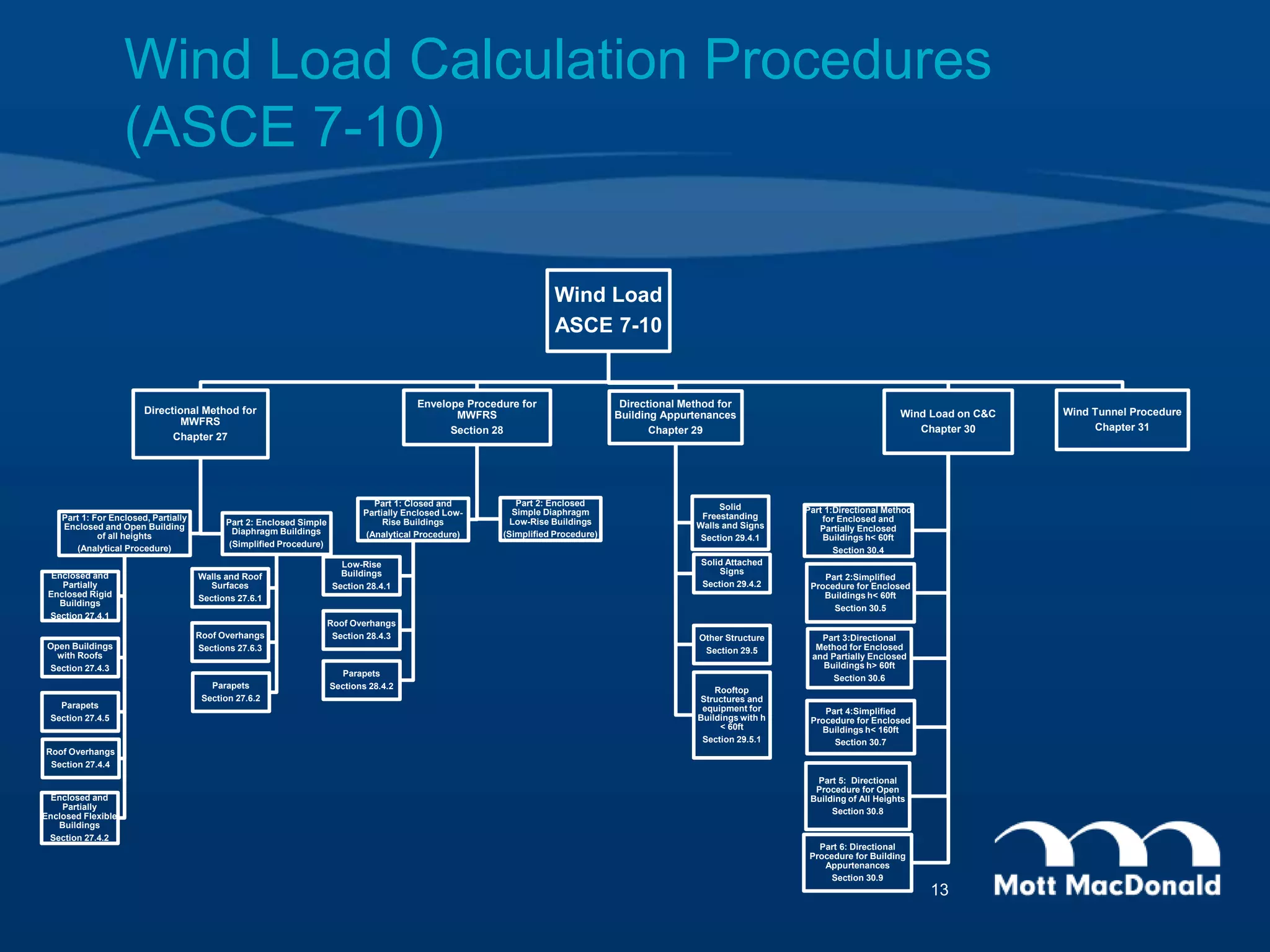
This document provides an overview of wind load calculation procedures according to the International Building Code (IBC) 2012 and American Society of Civil Engineers (ASCE) 7-10 standards. It defines important terms related to wind loads and explains changes made in ASCE 7-10 from the previous ASCE 7-05 standard. The major wind load calculation procedures covered are the directional procedure for buildings of all heights, the envelop procedure for low-rise buildings, and the wind tunnel procedure. Steps of the directional procedure are outlined, including determining the risk category, basic wind speed, wind parameters, velocity pressure coefficients, and velocity pressure.
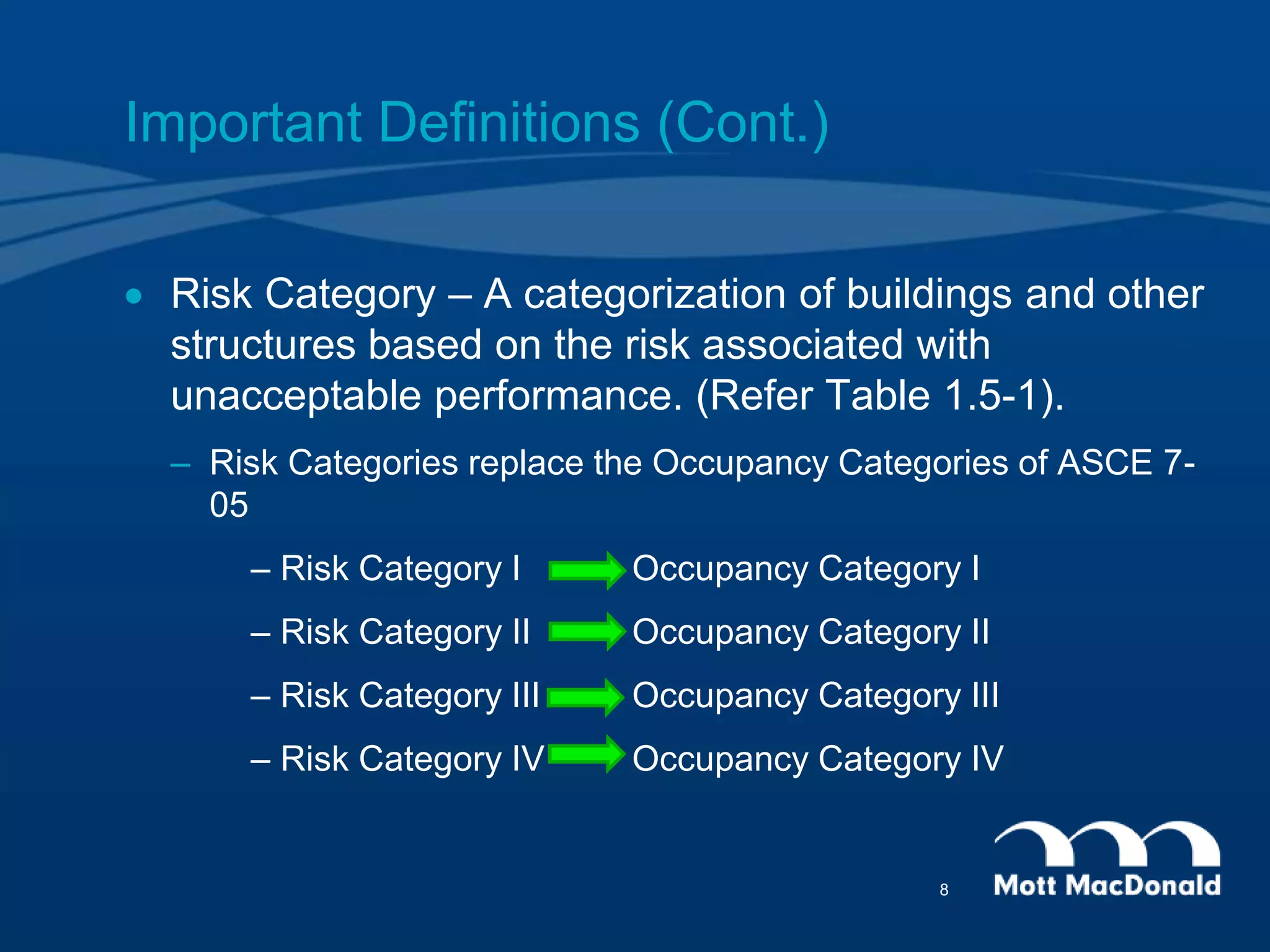
![Important Definitions (Cont.)
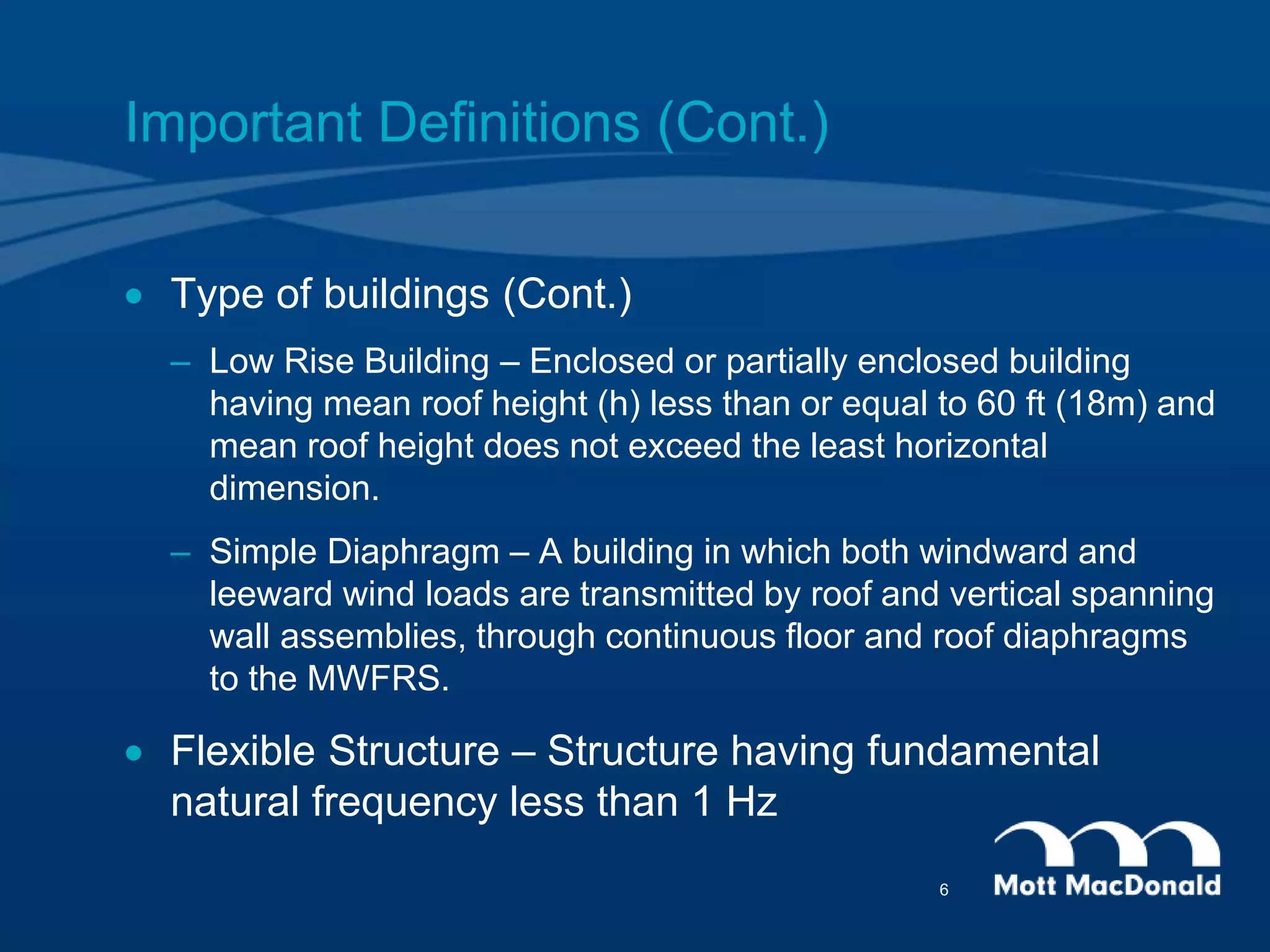
Type of buildings
Enclosure Classification
– Open Building – Building having each wall at least 80% open.
Ao > 0.8Ag
– Partially Enclosed Building – Ratio of total area of openings in a
wall receiving positive external pressure and sum of total
openings (roof and wall) is more than 10% and total area of
openings receiving positive pressure is more than 4 sq.ft.
• Ao > 1.10 Aoi, and
• Ao > min[4 sqft , 0.01Ag], and
• Aoi/Agi < 0.20
– Enclosed Building – A building that does not comply with the
requirements for open or partially enclosed building.
5](https://image.slidesharecdn.com/03c1b14e-6b4d-4932-a1df-279d64738333-150505071349-conversion-gate02/75/Wind_Load-5-2048.jpg)
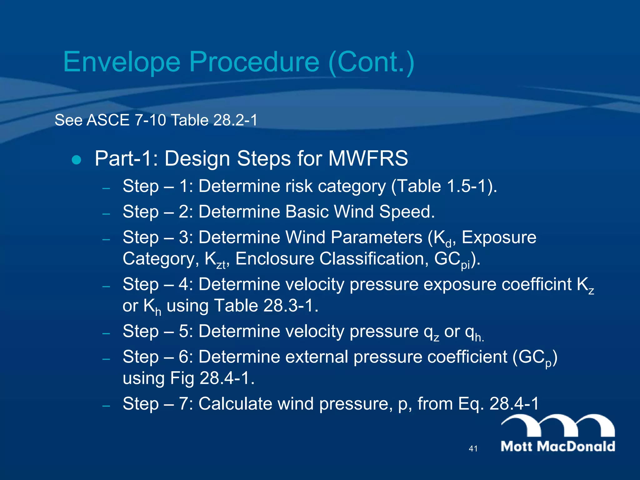
![Envelope Procedure (Cont.)
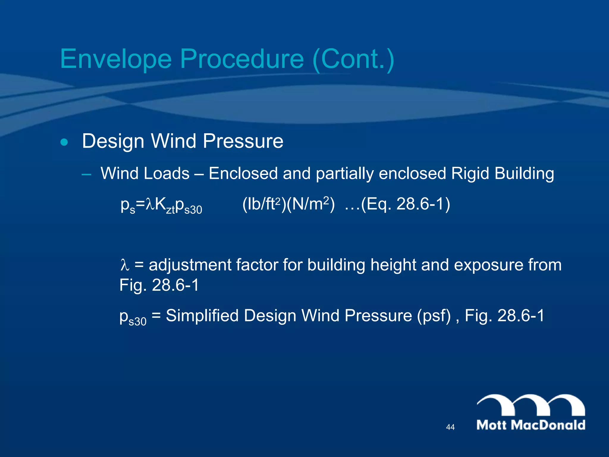
Design Wind Pressure
– Wind Loads – Enclosed and partially enclosed Rigid Building
p=qh[(GCpf ) - (GCpi )] (lb/ft2)(N/m2) …(Eq. 28.4-1)
External Pressure Coefficient (GCpf )
– The combined gust effect factor and external pressure
coefficients for low-rise buildings, (GCpf ), are not permitted to be
separated.
42](https://image.slidesharecdn.com/03c1b14e-6b4d-4932-a1df-279d64738333-150505071349-conversion-gate02/75/Wind_Load-42-2048.jpg)