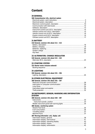
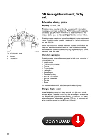
VOLVO CONSTRUCTION EQUIPMENT
SERVICE MANUAL
L60F/L70F/L90F
CONTENT
3 Electrical and Information System
Description
MORE CARE. BUILT IN.
WARNING!
Always read the booklet Safety before proceeding.
VOE 21 A 1002889
Foreword
This booklet is part of a complete service manual. Read the fore‐
word in the service manual.
1
3
Content
30 GENERAL
300 Comprehensive info, electrical system
Electrical system, work instructions...................................................................... 5
Electrical system, description ...............................................................................8
Electronic control system, description................................................................10
Communication with data buses........................................................................12
Software, description...........................................................................................13
Instrument control unit I-ECU, description........................................................14
Vehicle control unit V-ECU, description............................................................15
Vehicle control unit V2-ECU, description..........................................................16
Engine control unit E-ECU, description..............................................................16
Climate control unit ECC, description ...............................................................17
31 BATTERY
310 General, common info about 311 - 313
Battery, description..............................................................................................18
Battery, charging..................................................................................................19
Batteries, replacing..............................................................................................20
System voltage .....................................................................................................22
Key feed ................................................................................................................22
32 ALTERNATOR; CHARGE REGULATOR
320 General, common info about 321 - 322
Alternator 80 A, description .................................................................................23
33 STARTING SYSTEM
331 Starter motor inclusive solenoid
Booting sequence ................................................................................................24
35 LIGHTING
350 General, common info about 351 - 356
Lighting, description..............................................................................................25
36 OTHER ELECTRICAL EQUIPMENT
360 General, common info about 361 - 367
Reduced computer communication...................................................................28
Interruption in computer communication...........................................................29
Limp Home ............................................................................................................29
Intermittent wiper and washer ............................................................................30
Theft protection ....................................................................................................32
38 INSTRUMENT; SENSOR; WARNING AND INFORMATION
SYSTEM
380 General, common info about 383 - 387
Instruments ...........................................................................................................33
Instrument panels, position .............................................................................33
Middle instrument panel with warning lights ....................................................34
386 Sender, monitoring system
Washer fluid level.................................................................................................35
Fuel consumption.................................................................................................36
Travelling speed...................................................................................................37
Machine hours ......................................................................................................37
387 Warning/information unit, display unit
Information display, general................................................................................38
Information display, start lockout .......................................................................41
Information display, operating display...............................................................42
Information display, engine.................................................................................43
Information display, transmission........................................................................45
4
Information display, hydraulics............................................................................46
Information display, axles / brakes ....................................................................47
Information display, electrical system ...............................................................48
Information display, vehicle info .........................................................................49
Information display, vehicle messages .............................................................51
Information display, service................................................................................52
Information display, service mode.....................................................................53
Information display, settings...............................................................................55
Information display, check ..................................................................................56
Alarm, description ................................................................................................57
Central warning ....................................................................................................58
5
ELEC. SYSTEM; WARNING
SYSTEM; INFORMATION
SYSTEM; INSTRUMENTS
30 GENERAL
300 Comprehensive info, electrical
system
Electrical system, work instructions
Regarding: L60F, L70F, L90F
Batteries
1 Fully charged and otherwise satisfactory batteries must
always be used when working on the electrical system.
2 Test the batteries with an acid tester. The battery disconnect
switch should be turned off.
3 When installing a battery, make sure that the battery is con‐
nected with the correct polarity.
4 When changing batteries connected in series, make sure they
are of equal capacity, for example, 2 batteries of 105 Ah. The
batteries should have the same age (same quality), since the
charging current required to reach a certain voltage varies with
the battery's age.
5 If booster battery is required when starting, the following
instructions must be followed at all times; 191, Safety when
working with batteries and 191, Starting with booster batter‐
ies.
Charging
1 Before performing any tests of the alternator or regulator, the
batteries must be checked regarding insulation, loose fit, and
corrosion. Check the alternator belts.
2 For all testing of alternating current equipment, use “secure”
connections in order to prevent sparks and voltage transients.
A loose cable may result in destruction of both the alternator
and regulator.
3 Never disconnect the alternator leads while the engine is run‐
ning. This could damage both the alternator and regulator.
4 If the current alternator output socket should be connected to
the chassis, damage may occur to the alternator and regulator.
Components
When removing or installing components in the electrical system,
turn off the voltage supply with the battery disconnector.
6
Welding
For electric welding on the machine or on attachments on
machine:
- voltage feed turned off with battery disconnector
- connectors for all control units (ECUs) must be unplugged
NOTE! Ground the welding unit as close as possible to the weld‐
ing point.
8
Electrical system, description
Regarding: L60F, L70F, L90F
The machine has a 24 V electrical system with two 12 volt bat‐
teries connected in series, located on each side of the rear frame
in the counterweight.
The battery disconnector is located under the radiator casing.
Fuse FU74 is next to the battery disconnector and supplies volt‐
age to certain components (e.g., voltage converter for radio),
even when the battery disconnector is turned off.
Voltage feed takes place via a fuse box located in the engine
compartment. The fuse box contains main fuse as well as fuses
for preheating coil and secondary steering pump.
Relays and fuses are mainly located in the electrical distribution
box behind the operator's seat and are accessed by removing the
cover for the electrical distribution box. The cover's inside is pro‐
vided with a decal that informs which power-consuming compo‐
nent is connected to each relay and fuse. There is a built-in
terminal for fuse test in the electrical distribution box. The relays
in the electrical distribution box are interchangeable.
Components are marked according to which function group they
belong. The first two digits indicate function group and the other
digits are running numbers, e.g., SE2203.
NOTE! For working on the electrical system, follow the instruc‐
tions in section Electrical system, work instructions page 5.
1
3
4 V1048614
Fig.1 Position
1 Fuse box
2 Batteries
3 Battery disconnector, fuse FU74
4 Electrical distribution box
2
10
Electronic control system, description
Regarding: L60F, L70F, L90F
Vehicle electronics, general
Fig.2 Position of control units
1 Engine control unit E-ECU (MID128)
2 Vehicle control unit V-ECU (MID187)
3 Vehicle control unit V2-ECU (MID249)
4 Climate control unit ECC (MID146)
5 Instrument control unit I-ECU (MID140)
The machine electronics contain five control units that communi‐
cate with each other via two data buses. Each control unit pro‐
cesses values from sensors and operating controls, and controls
components so that desired function is obtained.
Control units included in the system are the instrument control
unit I-ECU, vehicle control unit V-ECU, vehicle control unit V2-
ECU, engine control unit E-ECU, and climate control unit ECC.
Machine electronics facilitate troubleshooting with a well-
designed and expansive diagnostic system. In case of electrical
malfunctions/errors, the operator receives a message on the
information panel.
For service personnel, the service tool VCADS Pro can be
plugged into sockets located by the electrical distribution box
behind the operator's seat.
Instrument control unit I-ECU is located in the instrument panel
and contains software for presenting operator information on the
information panel, including warning and control lights. The con‐
trol unit receives information from the other control units via data
bus.
Engine control unit E-ECU is located on intermediate wall in the
engine compartment and contains software for controlling engine
functions. The control unit receives information from the engine's
own sensors as well as from a data bus. The control unit also
sends information to the other control units via data bus.
2, 3 4 5
1
V1048627
11
Vehicle control units V-ECU and V2-ECU are located by the elec‐
trical distribution box behind the operator's seat and contains
software for controlling components and handling information
from sensors located outside the cab. The vehicle control unit is
connected to the other control units via data bus.
Climate control unit ECC are located inside the right side panel in
the cab and contain software for controlling heating, cooling, and
ventilation. The climate control unit is connected to the other con‐
trol units via data bus.
Communicationfor programming, changing parameters, and
reading out error codes, testing and checking components, etc.
is done with VCADS Pro. In VCADS Pro, MID-designations (Mes‐
sage Identification Description) are used for the control units.
Reading of input and output signals, setting certain functions,
reading off machine information, etc. can be performed with the
information panel.
If a malfunction occurs in any system, information is sent via the
data bus, which makes it possible to read off the information on
the information panel or by using VCADS Pro.
12
CAN2/J1939
CAN1/J1939
J1587/1708
VP
E-ECU
MID 128
ECC
MID 146
V2-ECU
MID 249
V-ECU
MID 187
I-ECU
MID 140
Communication with data buses
Regarding: L60F, L70F, L90F
V1047172
Fig.3 Communication
ECC Electronic climate control unit
E-ECU Engine control unit
I- ECU Instrument control unit
V-ECU Vehicle control unit
V2-ECU Vehicle control unit
VP Service socket for VCADS Pro
General
In principle, the machine electronics are based on all communi‐
cation between control units in the system taking place via two
data buses. The machine's control units are connected to the
buses to enable communication with each other.
Communication between the different control units as well as
reporting from control units to service sockets takes place on data
buses CAN1/J1939 and J1587/1708.
The buses follow SAE standards and consist of two pair-twisted
cables. The purpose of the twisted cabling is to protect the bus
from electrical interference.
If an error or malfunction should occur in any system, a signal is
sent out on the information bus which makes it possible to read
off the information either in the information display or with VCADS
Pro. In VCADS Pro, MID-designations (Message Identification
Description) are used for the control units.
The figure above shows the principle for how the control units and
service sockets are connected to the buses.
13
CAN1/J1939 control bus
System control signals are sent via this bus. The control bus is
very quick, which is necessary for control of the entire system to
work and quickly adapt to changing conditions.
The main communication alternative is the CAN1/J1939-bus.
However, for E-ECU, some control data is only sent on the J1587/
J1708-bus.
CAN2/J1939 control bus
CAN2/J1939 is used to obtain redundancy for CAN-communica‐
tion.
J1587/1708 information bus
The information bus is connected to the control units and service
socket. Information and diagnostic signals are sent on this bus.
In addition, some control data is sent from the engine control unit
via this bus.
The bus also acts as a “back-up” for the control bus if it does not
work for some reason. The system's status is continuously
updated and available for reading via the information bus.
By connecting VCADS Pro to service socket VP, it is possible to
read error codes, perform test, delete logged information, down‐
load parameters, and download software.
Software, description
Regarding: L60F, L70F, L90F
Software is stored in the control units. To determine which soft‐
ware is in the control units, the part number of the software (Main
software) is read in the information panel or with the service tool
VCADS Pro.
Updating of the machine's software is handled through release of
a new edition. The releases are designated with Year:edition, for
example, R2006:5 and gets a new part number.
Updating of software for control units takes place through down‐
loading of new software from VOLVO with VCADS Pro.
14
Instrument control unit I-ECU, description
Regarding: L60F, L70F, L90F
The instrument control unit is integrated with the main instrument
and receives information from the data bus. The information is
processed and shown on gauges, control lights, warning lights
and information display.
V1048600
Fig.4 Instrument control unit with information dis‐
play
Fig.5 Keypad for information display
V1047258
Functions
• Values for gear position, operating hours as well as status val‐
ues for parking brake and warning messages are processed
and result in a number of figures on the information panel.
• Special warnings, e.g., central warnings, low engine oil pres‐
sure are detected and the corresponding warning lights are
activated.
• Values for transmission oil temperature, coolant temperature
engine and fuel level are shown on gauges.
• Setting of display alternatives and parameter alternatives for
information panel.
• Storage and display of operating hours.
• PIN-code for theft protection via keypad
rpm
0
15
Fig.6 Vehicle control unit V-ECU
Vehicle control unit V-ECU, description
Regarding: L60F, L70F, L90F
The vehicle control unit has superior machine-related functional‐
ity and contains the following functions.
The vehicle control unit is located by the electrical distribution box
behind the operator's seat, and is connected to the other control
units via data link for communication with the other control units.
Functions
• Monitoring fuel level
• Monitoring of starter motor engagement
• Monitoring of system voltage
• Monitoring of pressure, temperature, level and filter for trans‐
mission oil
• Monitoring brake pressure
• Monitoring of level and temperature for hydraulic oil
• Monitoring of lubrication oil level for central lubrication
• Calculation of vehicle travel speed
• Parking brake
• Gear shifting strategy
• Request for engine rpm and/or torque limitation
• Transmission disengagement
• Engagement of differential lock
• Warming of hydraulic oil
• Boom Suspension System
• Secondary steering
• Cooling fan adjustment
• Reversal of cooling fan
• Attachment locking
• Brake pressure charging
V1047231
16
Vehicle control unit V2-ECU, description
Regarding: L60F, L70F, L90F
The vehicle control unit is the controlling unit in the system for the
following functions.
The vehicle control unit is located by the electrical distribution box
behind the operator's seat, and is connected to the other control
units via data link for communication with the other control units.
Functions
• Lever steering (CDC)
Fig.7 Vehicle control unit V2-ECU
Fig.8 Engine control unit
Engine control unit E-ECU, description
Regarding: L60F, L70F, L90F
The engine control unit is the central part of the injection system.
It is located on the partition wall in the engine compartment
installed in rubber-damper mounts.
The control unit continuously receives information from the accel‐
erator pedal and sensors on the engine as well as calculating the
fuel quantity and at which point in time the fuel shall be injected
into the cylinders via the injectors.
The control unit stores information if a malfunction should occur
or if any part of the system reacts abnormally. Sporadic malfunc‐
tions are stored in the control unit and can then be traced at a
later time.
Functions
• Control of fuel injection (Common Rail)
• Temperature monitoring
• Engagement of preheating
• Detecting engaged preheating
• Monitoring of water in fuel
• Monitoring of EGR-valve
• Automatic fuel shut-off at risk of high fuel temperature in the
return line when PRV-valve is open.
V1040516
V1047231
17
V1048568
Fig.9 Control unit ECC
Climate control unit ECC, description
Regarding: L60F, L70F, L90F
ECC, Electronic Climate Control, is a fully automatic climate con‐
trol system that controls fan speed, heat, cooling, fresh air inlet,
and air distribution. Desired temperature is set on the climate
control system's control panel , and the control unit handles all
other control.
The control unit receives continuous information about tempera‐
tures, pressure, rpm, etc. from a number of sensors. The control
unit is connected to the other control units via data link
J1587/1708 for communication. The control unit is located inside
of the right side panel in the cab.
Functions
• Control of temperature, air distribution, and ventilation in cab
• Control of soft start, AC-compressor
• Monitoring of temperatures and pressure
18
31 BATTERY
310 General, common info about 311 -
313
Battery, description
Regarding: L60F, L70F, L90F
The battery consists of two 12 V batteries connected in a series,
which together provide 24 V with a capacity of 220 Ah. The bat‐
teries are located behind the rear wheels on either side of the rear
frame. The battery disconnect switch is located under the radiator
casing at the rear of the machine on the right side.
The batteries should be in good condition when troubleshooting
the system. If needed, charge the batteries with a battery charger.
If the batteries do not take the charge, replace the batteries.
19
Battery, charging
Regarding: L60F, L70F, L90F
WARNING!
Hydrogen gas is formed during battery charging. Hydrogen gas
is flammable and may be explosive. A short circuit, open flame or
spark near the battery can cause a powerful explosion. Therefore,
ventilate well. Never smoke near batteries.
- Batteries must only be charged using a battery charger.
- Check the battery terminal connections and make sure that
they are adequately tightened and free from corrosion and dirt.
- Check the battery voltage when the batteries are at rest (before
starting). Each battery must be at least half-charged.
IMPORTANT! Always turn off the current to the battery charger
before disconnecting the charging clamps.
WARNING!
Corrosive sulphuric acid
The battery electrolyte includes corrosive sulphuric acid. Elec‐
trolyte spilled on bare skin must be removed immediately. Wash
with soap and plenty of water. If electrolyte gets into your eyes or
any other sensitive body part, rinse immediately with plenty of
water and seek immediate medical attention.
20
Batteries, replacing
Regarding: L60F, L70F, L90F
WARNING!
Batteries contain corrosive acid. Handle batteries according to
instructions in Section 3 and Section Safety.
Op. no.311-002
Removing
1 Place the machine in service position 1, see 191, Service
positions.
Fig.10
1 Battery disconnector
1
V1048901
2 Open the battery covers.
3 Remove the terminal caps.
4 Loosen and remove the cable terminals from the battery ter‐
minals.
NOTE! Start by removing the cable terminal from the minus
terminal.
5 Loosen the clamp and remove the battery.
Weight approx. 20 kg (44 lbs).
Fig.11
21
Installing
6 Lift the battery into place and fit the clamp.
7 Clean the battery terminals and cable terminals.
8 Install the cable terminals and lube with acid-free vaseline.
9 Restore the machine.
10 Start the machine and check that no error messages appear.
22
System voltage
Regarding: L60F, L70F, L90F
The function monitors the system voltage and informs the oper‐
ator when the system voltage is too high or too low.
Input signals Conditions for output functions Output functions
- Engine On/Off
- System voltage
- Voltage level > 31 V - Amber central warning
- Check
High system voltage
- Engine On
- Voltage level < 19 V
- Amber central warning
- Check
Low system voltage
Key feed
Regarding: L60F, L70F, L90F
Key feed is used as a condition in software functions to define
when voltage feed considered to be On and Off, respectively.
Input signals Conditions for output functions Output functions
- System voltage - Voltage < 8 V - Key feed Off
- Voltage > 12 V - Key feed On
23
32 ALTERNATOR; CHARGE
REGULATOR
320 General, common info about 321 -
322
Alternator 80 A, description
Regarding: L60F, L70F, L90F
The alternator is a 80 A alternating current generator with a nor‐
mal charge voltage of 28.3 V and a built-in charge regulator.
When the engine is turned off, the batteries normally give a volt‐
age of approx. 24-26 V, depending on their charging status. When
the engine is running, the batteries are normally charged by the
alternator, since the alternator’s normal charging voltage is higher
than the battery voltage.
If the batteries do not seem to take a charge, this may be due to
incorrect charge voltage from the alternator. Also check the acid‐
ity in the battery electrolyte, see Battery, charging page 19.
24
33 STARTING SYSTEM
331 Starter motor inclusive solenoid
Booting sequence
Regarding: L60F, L70F, L90F
When the battery disconnect switch SW3101 is switched on, there
is voltage up to ignition switch SW3301.
When Forward or Reverse gear is engaged (SW402), engage‐
ment of the starter motor is prevented and the message “Infor‐
mationGear sel. not in neutral” will be shown on the display unit..
If the starter motor is overheated the message “CheckHigh temp.
starter motorWait 5 min. before start” will be shown on the display
unit.
When there is any other fault in the starter circuit, the message
“CheckEngine failure” will be shown on the display unit.
When a starting attempt has failed, the ignition key must be turned
back to position 0 before a new starting attempt can be made.
See also Diagnostics and 370, Wiring diagram 303.
Input signals Conditions for output functions Output functions
- Ignition switch On/
Off
- Starter motor acti‐
vated (anti-theft
device) (a)
- Directional gear
steering column
- Engine On/Off
- Key feed
- Requested gear
- Ignition switch On (running position)
- Engine Off
- Requested gear = N
- Starter motor activated On
- Starter motor activated
message On
- Ignition switch On (running position)
- Engine Off
- Requested gear ≠ N
- Starter motor activated Off
- Starter motor activated
message Off
- Information
Gear sel. not in neutral
- Ignition switch On (running position)
- Engine Off
- Starter motor activated (anti-theft device) Off
- Starter motor activated Off
- Starter motor activated
message Off
- Key Feed On
- Ignition switch Off
- Engine Off
- Requested gear =
Requested gear (b)
a) If the anti-theft device is activated, starter motor activated is Off
b) Is used for trouble-shooting
The following applies in case of faulty input signals:
Input signal Assumed value in case of a fault
Ignition switch Off
Engine On
25
35 LIGHTING
350 General, common info about 351 -
356
Lighting, description
Regarding: L60F, L70F, L90F
Headlights
Headlights are operated with switch SW3501 located on the pillar
panel.
- Switch upper part pressed in = Headlights on.
- Switch in middle position = Parking and instrument lights on.
- Switch lower part pressed in = Headlights off.
High/low beams are controlled with SW3502, the right lever on
the steering column.
- Away from steering wheel = High beams.
- Neutral position = Low beams.
- Towards steering wheel = Headlight flash.
Control light on the front instrument panel indicates that high
beams are on.
See 370, Wiring diagram 304.
Work lights front
Work lights front are operated with switch SW3504 located on the
pillar panel.
- Switch upper part pressed in = Work lights front, cab, and
attachment on.
- Switch in middle position = Work lights cab on.
- Switch lower part pressed in = Work lights off.
Control light on the front instrument panel indicates that work
lights are on.
See 370, Wiring diagram 305.
For double work lights cab, see 370, Wiring diagram 312.
26
Work lights roof
Work lights rear are operated with switch SW3505 located on the
pillar panel.
- Switch upper part pressed in = Work lights cab and radiator
casing on when reverse gear is engaged.
- Switch in middle position = Work lights cab and radiator casing
on.
- Switch lower part pressed in = Work lights off.
Control light on the front instrument panel indicates that work
lights are on.
See 370, Wiring diagram 305.
For double work lights cab, see 370, Wiring diagram 312.
Work lights rear, continuous/gear-dependent (optional equip‐
ment)
With this function, it is only possible to select continuous or gear-
dependent engagement of work lights rear.
Selection of function with switch SW3505 located on the pillar
panel.
- Switch upper part pressed in = Work lights cab and radiator
casing on when reverse gear is engaged.
- Switch in middle position = Continuous work lights cab and
radiator casing on.
- Switch lower part pressed in = Continuous work lights cab and
radiator casing on.
Control light on the front instrument panel indicates that work
lights are on.
See 370, Wiring diagram 313.
Guide lights in switches and lighting in climate control system's
panel
Light intensity for guide lights in switches and lighting in climate
control system's panel are controlled with rheostat R3502.
- Rheostat's upper part pressed in = light intensity increases.
- Rheostat's lower part pressed in = light intensity decreases.
See 370, Wiring diagram 304.
27
Rotating beacon
Rotating beacon LA3624 is controlled with switch SW3624
located on the pillar panel.
Control light on the front instrument panel indicates that rotating
beacon is on.
See 370, Wiring diagram 306.
Electrically controlled battery disconnector (optional equipment)
Through the ignition SW3301, voltage is connected to the elec‐
trically controlled battery disconnector RE3101 of the ordinary
battery disconnector SW3101 is on.
Hold function for RE3101 is obtained via relay RE3102.
Stop of the machine is performed with the ignition or emergency
stop SW3102.
See 370, Wiring diagram 308.
Strobe light (optional equipment)
Strobe light LA3625 is on continuously as long as the battery dis‐
connector is on.
Control light on the front instrument panel indicates that the strobe
light is on.
See 370, Wiring diagram 306.
28
36 OTHER ELECTRICAL
EQUIPMENT
360 General, common info about 361 -
367
Reduced computer communication
Regarding: L60F, L70F, L90F
This function informs the operator in the event of ECU system
communication malfunction and continued operation with
reduced performance.
Input signals Conditions for output functions Output functions
- Network monitor‐
ing
- VCADS Pro
parameter HKP
- VCADS Pro
parameter HKQ
- VCADS Pro
parameter HKO
- VCADS Pro
parameter HKN
- VCADS Pro parameter HKP “1”
- No communication via J1587 on ECC
- Reduced function On
- Check
ECU Network Reduced
Communication
- VCADS Pro parameter HKQ “1”
- No communication via J1587 on V2-ECU
or
- No communication via CAN1 on V2-ECU
or
- No communication via CAN2 on V2-ECU
- Fail-safe mode On
- Check
ECU Network Reduced
Communication
- VCADS Pro parameter HKQ “1”
- No communication via J1587 and CAN1 on V2-ECU
or
- No communication via J1587 and CAN2 on V2-ECU
or
- No communication via CAN1 and CAN2 on V2-ECU
- Interruption in communica‐
tion between the ECUs On
- Check
ECU Network Communica‐
tion Interrupt
- No communication via J1587 on E-ECU
or
- No communication via CAN1 on E-ECU
- Fail-safe mode On
- Check
ECU Network Reduced
Communication
- No communication via J1587 and CAN1 on E-ECU - Interruption in communica‐
tion between the ECUs On
- Check
ECU Network Communica‐
tion Interrupt
- No communication via J1587 on V-ECU
or
- No communication via CAN1 on V-ECU
or
- No communication via CAN2 on V-ECU
- Fail-safe mode On
- Check
ECU Network Reduced
Communication
- No communication via J1587 and CAN1 on V-ECU
or
- No communication via J1587 and CAN2 on V-ECU
or
- No communication via CAN1 and CAN2 on V-ECU
- Interruption in communica‐
tion between the ECUs On
- Check
ECU Network Communica‐
tion Interrupt
29
Interruption in computer communication
Regarding: L60F, L70F, L90F
The function informs the operator about existing system errors as
regards the communications between the ECUs, continued oper‐
ation may lead to risk of damage.
Input signals Conditions for output functions Output functions
- Interrupted commu‐
nications between
the ECUs
- Interrupted communications - Check
ECU Network Communica‐
tion Interrupt
- Gear is moved to Neutral
Limp Home
Regarding: L60F, L70F, L90F
“Limp Home” means that the machine can only be operated in
2nd gear.
Input signals Conditions for output functions Output functions
- Requested gear
- Engine On/Off
- Accelerator pedal
- Computer communi‐
cation
- Engine On
- Requested gear falure
or
- Accelerator pedal sensor falure (SE2702)
or
- Reduced computer communication
- Requested gear ≤2
- Check
'Limp Home'
safety related failure
30
Intermittent wiper and washer
Regarding: L60F, L70F, L90F
The interval for the front wiper can be set with the aid of SW3602
as follows:
If SW3602 is set in position On, then Off and then again in position
On after X seconds, the time between the wiping actions will be
X seconds.
NOTE! The time between wiping actions cannot be shorter than
5 seconds or longer than 25 seconds. If an attempt is made at
setting the time between wiping actions to more than 60 seconds,
no new time will be set and instead the previous time interval will
continue to apply.
Intermittent wiper and front washer
Input signals Conditions for output functions Output functions
- Intermittent wiper
front, SW3602
- Washer front,
SW3608
- Intermittent wiper front On - Intermittent wiper front
active On for 0.5 second and
then Off for X seconds(a)
The sequence will be
repeated until Intermittent
wiper front is Off
- Intermittent wiper front Off
- Washer front Off
- Intermittent wiper front
active Off
- Washer front On - Intermittent wiper front
active On after 1 second.
- Washer front
- Washer front Off - Intermittent wiper front
active Off after 5 seconds.
a) If no interval has been set with SW3602, X = 7 seconds.
The following applies in case of faulty input signals:
Input signal Assumed value in case of a fault
Intermittent wiper front, SW3602 Off
Washer front, SW3608 Off
31
Intermittent wiper and rear washer
Input signals Conditions for output functions Output functions
- Wiper rear, SW3612
- Washer rear,
SW3612
- Wiper front, SW3602
- Intermittent wiper
front, SW3602
- Requested gear
- Wiper rear On
and
- Intermittent wiper front On
or
Wiper front On
and
- Requested gear ≠ R
- Wiper rear active On for 0.5
seconds and then Off for 7
seconds.
The sequence is repeated
until Wiper rear is Off or until
Wiper front and Intermittent
wiper front is Off
- Wiper rear On
and
- Intermittent wiper front On
or
Wiper front On
and
- Requested gear = R
- Wiper rear active On
- Washer rear On - Wiper rear active On after 1
second.
- Washer rear
- Washer front Off - Wiper rear active Off after 5
seconds.
The following applies in case of faulty input signals:
Input signal Assumed value in case of a fault
Wiper rear, SW3612 Off
Washer rear, SW3612 Off
Intermittent wiper front, SW3602 Off
Windscreen washer, SW3608 Off
Requested gear "N"
32
Theft protection
Regarding: L60F, L70F, L90F
The purpose of the function is to prevent theft of the machine. The
function is activated with VCADS Pro.
When the anti-theft device is activated, a correct four-digit code
must be entered via the keyboard and the "SELECT" button
pressed before the engine can be started, the parking brake
released and a directional gear selected.
Selection and change of anti-theft code is done with the VCADS
Pro parameter ABQ. The code is stored in control units I-ECU and
V-ECU.
NOTE! When a starting attempt is made while the anti-theft device
is activated, the starter motor can crank the engine, but the engine
will not start.
The engine can be restarted without having to enter the code
within the delay time (VCADS Pro parameter FXZ).
Input signals Conditions for output functions Output functions
- VCADS Pro parame‐
ter ABP
- VCADS Pro parame‐
ter ABQ
- VCADS Pro parame‐
ter FXZ
- Keyboard
- Key feed
- Time since latest
ignition switch Off
General conditions for the function
- VCADS Pro parameter ABP "On"
(activation of function)
- VCADS Pro parameter ABQ "****"
(anti-theft code)
- VCADS Pro parameter FXZ
(delay)
Deactivation of anti-theft device
- Ignition switch On (running position)
Display unit shows
Start lockout
Enter code ****
- Enter correct four-digit code via the keyboard and
then press "SELECT"
- The anti-theft device is
deactivated
The engine can now be
started, the parking brake
released and directional gear
selected.
Activation of anti-theft device
- Ignition switch Off (position 0) > VCADS Pro param‐
eter FXZ (delay time)
- Directional gear N
- Engine shutdown
- Parking brake applied,
MA5501 de-energised (a)
a) Prevents operation of the parking brake via switch SW5501.
The following applies in case of faulty input signals:
Input signal Assumed value in case of a fault
VCADS Pro parameter ABP “ON”
VCADS Pro parameter FXZ System default value
33
1
2
3
1015939
4 V1048999
38 INSTRUMENT; SENSOR;
WARNING AND INFORMATION
SYSTEM
380 General, common info about 383 -
387
Instruments
Regarding: L60F, L70F, L90F
Instrument panels, position
Fig.12 Instrument panels
1 Front instrument panel (central instrument, switches, keypad for information display unit)
2 Roof panel (climate control system)
3 Pillar panel (mode selector, switches, ignition, hand throttle control, and electric power socket 12 V.)
4 Rear cab wall with electric power socket 24 V, hour meter, electrical distribution box with fuses and relays. Socket for
service tool.
34
1 2 3
10 11
8
9 12
13
5
6
7
14
4
0
rpm
15 17
V1049000
Middle instrument panel with warning lights
Regarding: L60F, L70F, L90F
Fig.13
1 Amber central warning 11 Display unit
2 Red central warning 12 Boom Suspension System activated (green)
3 Information symbol (green) 13 Differential lock engaged (green)
4 High beams (blue) 14 Lever steering activated (green)
5 Rotating beacon (amber) 15 Fuel level
6 Working lights (amber) 16 Transmission oil temperature
7 Parking brake applied (red) 17 Coolant temperature
8 Charging, battery (red)
9 Direction indicator left (green)
10 Direction indicator right (green)
35
386 Sender, monitoring system
Washer fluid level
Regarding: L60F, L70F, L90F
The function monitors the washer fluid level and triggers an alarm
when the level is low.
Input signals Conditions for output functions Output functions
- Window washer fluid
level, SE3601
- Low level > 20 seconds - Information
Low washer fluid level
The following applies in case of faulty input signals:
Input signal Assumed value in case of a fault
Window washer fluid level Normal
36
Fuel consumption
Regarding: L60F, L70F, L90F
The function calculates the machine's fuel consumption and dis‐
plays it on the information panel.
Calculations of consumption are displayed according to the fol‐
lowing:
- Instantaneous consumption in litres per hour.
- Average consumption in litres per hour.
- Total consumption in litres since last reset; up to 99999 litres.
- Residual time for fuel.
Display of consumption and reset of the same takes place in
information figure Vehicle info, Operational Data, see also Infor‐
mation display, operating display page 42.
Fuel consumption, total
Input signals Conditions for output functions Output functions
- VCADS Pro parame‐
ter GZC
- Reset
- Instantaneous con‐
sumption
Overall conditions for the function:
- VCADS Pro parameter GZC “ON”
- Vehicle info
Operational Data
Total:(a)
- Reset Yes
or
- Total fuel consumption > 99999
- Total fuel consumption = 0
a) Shows total fuel consumption since last reset.
The following applies in case of incorrect input signals:
Input Assumed value in case of error
VCADS Pro parameter GZC “OFF”
Reset No
Fuel consumption, average
Input signals Conditions for output functions Output functions
- VCADS Pro parame‐
ter GZD
- Reset
- Total fuel consump‐
tion
- Machine time
Overall conditions for the function:
- VCADS Pro parameter GZD “ON”
- Total fuel consumption / Machine hours - Vehicle info
Operational Data
Avg.:(a)
- Reset Yes - Average fuel consumption =
0
a) Shows average fuel consumption since last reset.
The following applies in case of incorrect input signals:
Input Assumed value in case of error
VCADS Pro parameter GZD “OFF”
Reset No
In case any of the input signals Total fuel consumption or Machine
hours is incorrect, the output signal is incorrect until Reset = Yes
37
Fuel consumption, residual time
Input signals Conditions for output functions Output functions
- VCADS Pro parame‐
ter HLF
- VCADS Pro parame‐
ter HLI
- Fuel level, SE2303
- Calculated fuel level
(a)
Overall conditions for the function:
- VCADS Pro parameter HLF “ON”
- Calculated fuel level / Average consumption - Vehicle info
Operational Data
Resid. time fuel:(b)
- Engine On/Off
- Total fuel consump‐
tion
a) Calculated value > fuel level
b) Shows calculated time remaining before fuel runs out.
The following applies in case of incorrect input signals:
Input Assumed value in case of error
VCADS Pro parameter HLF “OFF”
In case any other input signal is incorrect, the output signal
becomes incorrect.
Travelling speed
Regarding: L60F, L70F, L90F
The function calculates and informs the operator about the speed.
The speed is used as input signal to several functions.
Input signals Conditions for output functions Output functions
- VCADS Pro parame‐
ter QM
- Output speed trans‐
mission, SE4307
- (Output speed transmission/axle ratio) x VCADS Pro
parameter QM
- Distance per second
- Distance per second x (3.6 / 1000) - Speed
In case of any input signals being faulty, the output signals are
considered to be faulty.
Machine hours
Regarding: L60F, L70F, L90F
The function calculates and shows on the display unit the time the
engine of the machine has been On since previous Reset / Setting
to zero.
Input signals Conditions for output functions Output functions
- VCADS Pro parame‐
ter BMH
- Engine On/Off
- Engine On - Vehicle info
Operational Data
Machine hours
38
387 Warning/information unit, display
unit
Information display, general
Regarding: L60F, L70F, L90F
1 2
The information panel provides the operator with information,
messages, warnings, and alarms. With the keypad, the operator
i can select group/function from which to read information. The
F C
C
Fig.14 Instrument panel
1 Keypad
2 Display unit
V1047353
keypad is also used to make settings and enter number values.
The information panel and keypad are located on the instrument
panel. The information panel is connected to the instrument con‐
trol unit (I-ECU).
When the machine is started, the latest figure is shown from the
time that the machine was turned off. The information can be
adapted to the operator by selecting language and display format
for units, time, and date.
Information organization
The information in the information panel is built up in a number of
groups/functions:
- Initial display
- Operating information
- Engine
- Transmission
- Hydraulics
- Axles/Brakes
- Electrical system
- Vehicle information
- Vehicle messages
- Service
- Setup
For detailed information, see description of each group.
Changing display screen
Move between groups/functions with the function keys on the
keypad. When changing group/function, you always arrive at the
top figure in each function group. Return to the figure for “oper‐
ating information” takes place with the ESC-key or automatically
when machine speed is over 20 km/h (12 mph).

Volvo L70F Wheel Loader Engine Service Manual

  • 1.
    VOLVO CONSTRUCTION EQUIPMENT SERVICEMANUAL L60F/L70F/L90F CONTENT 3 Electrical and Information System Description
  • 2.
  • 4.
    WARNING! Always read thebooklet Safety before proceeding. VOE 21 A 1002889 Foreword This booklet is part of a complete service manual. Read the fore‐ word in the service manual. 1
  • 7.
    3 Content 30 GENERAL 300 Comprehensiveinfo, electrical system Electrical system, work instructions...................................................................... 5 Electrical system, description ...............................................................................8 Electronic control system, description................................................................10 Communication with data buses........................................................................12 Software, description...........................................................................................13 Instrument control unit I-ECU, description........................................................14 Vehicle control unit V-ECU, description............................................................15 Vehicle control unit V2-ECU, description..........................................................16 Engine control unit E-ECU, description..............................................................16 Climate control unit ECC, description ...............................................................17 31 BATTERY 310 General, common info about 311 - 313 Battery, description..............................................................................................18 Battery, charging..................................................................................................19 Batteries, replacing..............................................................................................20 System voltage .....................................................................................................22 Key feed ................................................................................................................22 32 ALTERNATOR; CHARGE REGULATOR 320 General, common info about 321 - 322 Alternator 80 A, description .................................................................................23 33 STARTING SYSTEM 331 Starter motor inclusive solenoid Booting sequence ................................................................................................24 35 LIGHTING 350 General, common info about 351 - 356 Lighting, description..............................................................................................25 36 OTHER ELECTRICAL EQUIPMENT 360 General, common info about 361 - 367 Reduced computer communication...................................................................28 Interruption in computer communication...........................................................29 Limp Home ............................................................................................................29 Intermittent wiper and washer ............................................................................30 Theft protection ....................................................................................................32 38 INSTRUMENT; SENSOR; WARNING AND INFORMATION SYSTEM 380 General, common info about 383 - 387 Instruments ...........................................................................................................33 Instrument panels, position .............................................................................33 Middle instrument panel with warning lights ....................................................34 386 Sender, monitoring system Washer fluid level.................................................................................................35 Fuel consumption.................................................................................................36 Travelling speed...................................................................................................37 Machine hours ......................................................................................................37 387 Warning/information unit, display unit Information display, general................................................................................38 Information display, start lockout .......................................................................41 Information display, operating display...............................................................42 Information display, engine.................................................................................43 Information display, transmission........................................................................45
  • 8.
    4 Information display, hydraulics............................................................................46 Informationdisplay, axles / brakes ....................................................................47 Information display, electrical system ...............................................................48 Information display, vehicle info .........................................................................49 Information display, vehicle messages .............................................................51 Information display, service................................................................................52 Information display, service mode.....................................................................53 Information display, settings...............................................................................55 Information display, check ..................................................................................56 Alarm, description ................................................................................................57 Central warning ....................................................................................................58
  • 9.
    5 ELEC. SYSTEM; WARNING SYSTEM;INFORMATION SYSTEM; INSTRUMENTS 30 GENERAL 300 Comprehensive info, electrical system Electrical system, work instructions Regarding: L60F, L70F, L90F Batteries 1 Fully charged and otherwise satisfactory batteries must always be used when working on the electrical system. 2 Test the batteries with an acid tester. The battery disconnect switch should be turned off. 3 When installing a battery, make sure that the battery is con‐ nected with the correct polarity. 4 When changing batteries connected in series, make sure they are of equal capacity, for example, 2 batteries of 105 Ah. The batteries should have the same age (same quality), since the charging current required to reach a certain voltage varies with the battery's age. 5 If booster battery is required when starting, the following instructions must be followed at all times; 191, Safety when working with batteries and 191, Starting with booster batter‐ ies. Charging 1 Before performing any tests of the alternator or regulator, the batteries must be checked regarding insulation, loose fit, and corrosion. Check the alternator belts. 2 For all testing of alternating current equipment, use “secure” connections in order to prevent sparks and voltage transients. A loose cable may result in destruction of both the alternator and regulator. 3 Never disconnect the alternator leads while the engine is run‐ ning. This could damage both the alternator and regulator. 4 If the current alternator output socket should be connected to the chassis, damage may occur to the alternator and regulator. Components When removing or installing components in the electrical system, turn off the voltage supply with the battery disconnector.
  • 10.
    6 Welding For electric weldingon the machine or on attachments on machine: - voltage feed turned off with battery disconnector - connectors for all control units (ECUs) must be unplugged NOTE! Ground the welding unit as close as possible to the weld‐ ing point.
  • 12.
    8 Electrical system, description Regarding:L60F, L70F, L90F The machine has a 24 V electrical system with two 12 volt bat‐ teries connected in series, located on each side of the rear frame in the counterweight. The battery disconnector is located under the radiator casing. Fuse FU74 is next to the battery disconnector and supplies volt‐ age to certain components (e.g., voltage converter for radio), even when the battery disconnector is turned off. Voltage feed takes place via a fuse box located in the engine compartment. The fuse box contains main fuse as well as fuses for preheating coil and secondary steering pump. Relays and fuses are mainly located in the electrical distribution box behind the operator's seat and are accessed by removing the cover for the electrical distribution box. The cover's inside is pro‐ vided with a decal that informs which power-consuming compo‐ nent is connected to each relay and fuse. There is a built-in terminal for fuse test in the electrical distribution box. The relays in the electrical distribution box are interchangeable. Components are marked according to which function group they belong. The first two digits indicate function group and the other digits are running numbers, e.g., SE2203. NOTE! For working on the electrical system, follow the instruc‐ tions in section Electrical system, work instructions page 5. 1 3 4 V1048614 Fig.1 Position 1 Fuse box 2 Batteries 3 Battery disconnector, fuse FU74 4 Electrical distribution box 2
  • 14.
    10 Electronic control system,description Regarding: L60F, L70F, L90F Vehicle electronics, general Fig.2 Position of control units 1 Engine control unit E-ECU (MID128) 2 Vehicle control unit V-ECU (MID187) 3 Vehicle control unit V2-ECU (MID249) 4 Climate control unit ECC (MID146) 5 Instrument control unit I-ECU (MID140) The machine electronics contain five control units that communi‐ cate with each other via two data buses. Each control unit pro‐ cesses values from sensors and operating controls, and controls components so that desired function is obtained. Control units included in the system are the instrument control unit I-ECU, vehicle control unit V-ECU, vehicle control unit V2- ECU, engine control unit E-ECU, and climate control unit ECC. Machine electronics facilitate troubleshooting with a well- designed and expansive diagnostic system. In case of electrical malfunctions/errors, the operator receives a message on the information panel. For service personnel, the service tool VCADS Pro can be plugged into sockets located by the electrical distribution box behind the operator's seat. Instrument control unit I-ECU is located in the instrument panel and contains software for presenting operator information on the information panel, including warning and control lights. The con‐ trol unit receives information from the other control units via data bus. Engine control unit E-ECU is located on intermediate wall in the engine compartment and contains software for controlling engine functions. The control unit receives information from the engine's own sensors as well as from a data bus. The control unit also sends information to the other control units via data bus. 2, 3 4 5 1 V1048627
  • 15.
    11 Vehicle control unitsV-ECU and V2-ECU are located by the elec‐ trical distribution box behind the operator's seat and contains software for controlling components and handling information from sensors located outside the cab. The vehicle control unit is connected to the other control units via data bus. Climate control unit ECC are located inside the right side panel in the cab and contain software for controlling heating, cooling, and ventilation. The climate control unit is connected to the other con‐ trol units via data bus. Communicationfor programming, changing parameters, and reading out error codes, testing and checking components, etc. is done with VCADS Pro. In VCADS Pro, MID-designations (Mes‐ sage Identification Description) are used for the control units. Reading of input and output signals, setting certain functions, reading off machine information, etc. can be performed with the information panel. If a malfunction occurs in any system, information is sent via the data bus, which makes it possible to read off the information on the information panel or by using VCADS Pro.
  • 16.
    12 CAN2/J1939 CAN1/J1939 J1587/1708 VP E-ECU MID 128 ECC MID 146 V2-ECU MID249 V-ECU MID 187 I-ECU MID 140 Communication with data buses Regarding: L60F, L70F, L90F V1047172 Fig.3 Communication ECC Electronic climate control unit E-ECU Engine control unit I- ECU Instrument control unit V-ECU Vehicle control unit V2-ECU Vehicle control unit VP Service socket for VCADS Pro General In principle, the machine electronics are based on all communi‐ cation between control units in the system taking place via two data buses. The machine's control units are connected to the buses to enable communication with each other. Communication between the different control units as well as reporting from control units to service sockets takes place on data buses CAN1/J1939 and J1587/1708. The buses follow SAE standards and consist of two pair-twisted cables. The purpose of the twisted cabling is to protect the bus from electrical interference. If an error or malfunction should occur in any system, a signal is sent out on the information bus which makes it possible to read off the information either in the information display or with VCADS Pro. In VCADS Pro, MID-designations (Message Identification Description) are used for the control units. The figure above shows the principle for how the control units and service sockets are connected to the buses.
  • 17.
    13 CAN1/J1939 control bus Systemcontrol signals are sent via this bus. The control bus is very quick, which is necessary for control of the entire system to work and quickly adapt to changing conditions. The main communication alternative is the CAN1/J1939-bus. However, for E-ECU, some control data is only sent on the J1587/ J1708-bus. CAN2/J1939 control bus CAN2/J1939 is used to obtain redundancy for CAN-communica‐ tion. J1587/1708 information bus The information bus is connected to the control units and service socket. Information and diagnostic signals are sent on this bus. In addition, some control data is sent from the engine control unit via this bus. The bus also acts as a “back-up” for the control bus if it does not work for some reason. The system's status is continuously updated and available for reading via the information bus. By connecting VCADS Pro to service socket VP, it is possible to read error codes, perform test, delete logged information, down‐ load parameters, and download software. Software, description Regarding: L60F, L70F, L90F Software is stored in the control units. To determine which soft‐ ware is in the control units, the part number of the software (Main software) is read in the information panel or with the service tool VCADS Pro. Updating of the machine's software is handled through release of a new edition. The releases are designated with Year:edition, for example, R2006:5 and gets a new part number. Updating of software for control units takes place through down‐ loading of new software from VOLVO with VCADS Pro.
  • 18.
    14 Instrument control unitI-ECU, description Regarding: L60F, L70F, L90F The instrument control unit is integrated with the main instrument and receives information from the data bus. The information is processed and shown on gauges, control lights, warning lights and information display. V1048600 Fig.4 Instrument control unit with information dis‐ play Fig.5 Keypad for information display V1047258 Functions • Values for gear position, operating hours as well as status val‐ ues for parking brake and warning messages are processed and result in a number of figures on the information panel. • Special warnings, e.g., central warnings, low engine oil pres‐ sure are detected and the corresponding warning lights are activated. • Values for transmission oil temperature, coolant temperature engine and fuel level are shown on gauges. • Setting of display alternatives and parameter alternatives for information panel. • Storage and display of operating hours. • PIN-code for theft protection via keypad rpm 0
  • 19.
    15 Fig.6 Vehicle controlunit V-ECU Vehicle control unit V-ECU, description Regarding: L60F, L70F, L90F The vehicle control unit has superior machine-related functional‐ ity and contains the following functions. The vehicle control unit is located by the electrical distribution box behind the operator's seat, and is connected to the other control units via data link for communication with the other control units. Functions • Monitoring fuel level • Monitoring of starter motor engagement • Monitoring of system voltage • Monitoring of pressure, temperature, level and filter for trans‐ mission oil • Monitoring brake pressure • Monitoring of level and temperature for hydraulic oil • Monitoring of lubrication oil level for central lubrication • Calculation of vehicle travel speed • Parking brake • Gear shifting strategy • Request for engine rpm and/or torque limitation • Transmission disengagement • Engagement of differential lock • Warming of hydraulic oil • Boom Suspension System • Secondary steering • Cooling fan adjustment • Reversal of cooling fan • Attachment locking • Brake pressure charging V1047231
  • 20.
    16 Vehicle control unitV2-ECU, description Regarding: L60F, L70F, L90F The vehicle control unit is the controlling unit in the system for the following functions. The vehicle control unit is located by the electrical distribution box behind the operator's seat, and is connected to the other control units via data link for communication with the other control units. Functions • Lever steering (CDC) Fig.7 Vehicle control unit V2-ECU Fig.8 Engine control unit Engine control unit E-ECU, description Regarding: L60F, L70F, L90F The engine control unit is the central part of the injection system. It is located on the partition wall in the engine compartment installed in rubber-damper mounts. The control unit continuously receives information from the accel‐ erator pedal and sensors on the engine as well as calculating the fuel quantity and at which point in time the fuel shall be injected into the cylinders via the injectors. The control unit stores information if a malfunction should occur or if any part of the system reacts abnormally. Sporadic malfunc‐ tions are stored in the control unit and can then be traced at a later time. Functions • Control of fuel injection (Common Rail) • Temperature monitoring • Engagement of preheating • Detecting engaged preheating • Monitoring of water in fuel • Monitoring of EGR-valve • Automatic fuel shut-off at risk of high fuel temperature in the return line when PRV-valve is open. V1040516 V1047231
  • 21.
    17 V1048568 Fig.9 Control unitECC Climate control unit ECC, description Regarding: L60F, L70F, L90F ECC, Electronic Climate Control, is a fully automatic climate con‐ trol system that controls fan speed, heat, cooling, fresh air inlet, and air distribution. Desired temperature is set on the climate control system's control panel , and the control unit handles all other control. The control unit receives continuous information about tempera‐ tures, pressure, rpm, etc. from a number of sensors. The control unit is connected to the other control units via data link J1587/1708 for communication. The control unit is located inside of the right side panel in the cab. Functions • Control of temperature, air distribution, and ventilation in cab • Control of soft start, AC-compressor • Monitoring of temperatures and pressure
  • 22.
    18 31 BATTERY 310 General,common info about 311 - 313 Battery, description Regarding: L60F, L70F, L90F The battery consists of two 12 V batteries connected in a series, which together provide 24 V with a capacity of 220 Ah. The bat‐ teries are located behind the rear wheels on either side of the rear frame. The battery disconnect switch is located under the radiator casing at the rear of the machine on the right side. The batteries should be in good condition when troubleshooting the system. If needed, charge the batteries with a battery charger. If the batteries do not take the charge, replace the batteries.
  • 23.
    19 Battery, charging Regarding: L60F,L70F, L90F WARNING! Hydrogen gas is formed during battery charging. Hydrogen gas is flammable and may be explosive. A short circuit, open flame or spark near the battery can cause a powerful explosion. Therefore, ventilate well. Never smoke near batteries. - Batteries must only be charged using a battery charger. - Check the battery terminal connections and make sure that they are adequately tightened and free from corrosion and dirt. - Check the battery voltage when the batteries are at rest (before starting). Each battery must be at least half-charged. IMPORTANT! Always turn off the current to the battery charger before disconnecting the charging clamps. WARNING! Corrosive sulphuric acid The battery electrolyte includes corrosive sulphuric acid. Elec‐ trolyte spilled on bare skin must be removed immediately. Wash with soap and plenty of water. If electrolyte gets into your eyes or any other sensitive body part, rinse immediately with plenty of water and seek immediate medical attention.
  • 24.
    20 Batteries, replacing Regarding: L60F,L70F, L90F WARNING! Batteries contain corrosive acid. Handle batteries according to instructions in Section 3 and Section Safety. Op. no.311-002 Removing 1 Place the machine in service position 1, see 191, Service positions. Fig.10 1 Battery disconnector 1 V1048901 2 Open the battery covers. 3 Remove the terminal caps. 4 Loosen and remove the cable terminals from the battery ter‐ minals. NOTE! Start by removing the cable terminal from the minus terminal. 5 Loosen the clamp and remove the battery. Weight approx. 20 kg (44 lbs). Fig.11
  • 25.
    21 Installing 6 Lift thebattery into place and fit the clamp. 7 Clean the battery terminals and cable terminals. 8 Install the cable terminals and lube with acid-free vaseline. 9 Restore the machine. 10 Start the machine and check that no error messages appear.
  • 26.
    22 System voltage Regarding: L60F,L70F, L90F The function monitors the system voltage and informs the oper‐ ator when the system voltage is too high or too low. Input signals Conditions for output functions Output functions - Engine On/Off - System voltage - Voltage level > 31 V - Amber central warning - Check High system voltage - Engine On - Voltage level < 19 V - Amber central warning - Check Low system voltage Key feed Regarding: L60F, L70F, L90F Key feed is used as a condition in software functions to define when voltage feed considered to be On and Off, respectively. Input signals Conditions for output functions Output functions - System voltage - Voltage < 8 V - Key feed Off - Voltage > 12 V - Key feed On
  • 27.
    23 32 ALTERNATOR; CHARGE REGULATOR 320General, common info about 321 - 322 Alternator 80 A, description Regarding: L60F, L70F, L90F The alternator is a 80 A alternating current generator with a nor‐ mal charge voltage of 28.3 V and a built-in charge regulator. When the engine is turned off, the batteries normally give a volt‐ age of approx. 24-26 V, depending on their charging status. When the engine is running, the batteries are normally charged by the alternator, since the alternator’s normal charging voltage is higher than the battery voltage. If the batteries do not seem to take a charge, this may be due to incorrect charge voltage from the alternator. Also check the acid‐ ity in the battery electrolyte, see Battery, charging page 19.
  • 28.
    24 33 STARTING SYSTEM 331Starter motor inclusive solenoid Booting sequence Regarding: L60F, L70F, L90F When the battery disconnect switch SW3101 is switched on, there is voltage up to ignition switch SW3301. When Forward or Reverse gear is engaged (SW402), engage‐ ment of the starter motor is prevented and the message “Infor‐ mationGear sel. not in neutral” will be shown on the display unit.. If the starter motor is overheated the message “CheckHigh temp. starter motorWait 5 min. before start” will be shown on the display unit. When there is any other fault in the starter circuit, the message “CheckEngine failure” will be shown on the display unit. When a starting attempt has failed, the ignition key must be turned back to position 0 before a new starting attempt can be made. See also Diagnostics and 370, Wiring diagram 303. Input signals Conditions for output functions Output functions - Ignition switch On/ Off - Starter motor acti‐ vated (anti-theft device) (a) - Directional gear steering column - Engine On/Off - Key feed - Requested gear - Ignition switch On (running position) - Engine Off - Requested gear = N - Starter motor activated On - Starter motor activated message On - Ignition switch On (running position) - Engine Off - Requested gear ≠ N - Starter motor activated Off - Starter motor activated message Off - Information Gear sel. not in neutral - Ignition switch On (running position) - Engine Off - Starter motor activated (anti-theft device) Off - Starter motor activated Off - Starter motor activated message Off - Key Feed On - Ignition switch Off - Engine Off - Requested gear = Requested gear (b) a) If the anti-theft device is activated, starter motor activated is Off b) Is used for trouble-shooting The following applies in case of faulty input signals: Input signal Assumed value in case of a fault Ignition switch Off Engine On
  • 29.
    25 35 LIGHTING 350 General,common info about 351 - 356 Lighting, description Regarding: L60F, L70F, L90F Headlights Headlights are operated with switch SW3501 located on the pillar panel. - Switch upper part pressed in = Headlights on. - Switch in middle position = Parking and instrument lights on. - Switch lower part pressed in = Headlights off. High/low beams are controlled with SW3502, the right lever on the steering column. - Away from steering wheel = High beams. - Neutral position = Low beams. - Towards steering wheel = Headlight flash. Control light on the front instrument panel indicates that high beams are on. See 370, Wiring diagram 304. Work lights front Work lights front are operated with switch SW3504 located on the pillar panel. - Switch upper part pressed in = Work lights front, cab, and attachment on. - Switch in middle position = Work lights cab on. - Switch lower part pressed in = Work lights off. Control light on the front instrument panel indicates that work lights are on. See 370, Wiring diagram 305. For double work lights cab, see 370, Wiring diagram 312.
  • 30.
    26 Work lights roof Worklights rear are operated with switch SW3505 located on the pillar panel. - Switch upper part pressed in = Work lights cab and radiator casing on when reverse gear is engaged. - Switch in middle position = Work lights cab and radiator casing on. - Switch lower part pressed in = Work lights off. Control light on the front instrument panel indicates that work lights are on. See 370, Wiring diagram 305. For double work lights cab, see 370, Wiring diagram 312. Work lights rear, continuous/gear-dependent (optional equip‐ ment) With this function, it is only possible to select continuous or gear- dependent engagement of work lights rear. Selection of function with switch SW3505 located on the pillar panel. - Switch upper part pressed in = Work lights cab and radiator casing on when reverse gear is engaged. - Switch in middle position = Continuous work lights cab and radiator casing on. - Switch lower part pressed in = Continuous work lights cab and radiator casing on. Control light on the front instrument panel indicates that work lights are on. See 370, Wiring diagram 313. Guide lights in switches and lighting in climate control system's panel Light intensity for guide lights in switches and lighting in climate control system's panel are controlled with rheostat R3502. - Rheostat's upper part pressed in = light intensity increases. - Rheostat's lower part pressed in = light intensity decreases. See 370, Wiring diagram 304.
  • 31.
    27 Rotating beacon Rotating beaconLA3624 is controlled with switch SW3624 located on the pillar panel. Control light on the front instrument panel indicates that rotating beacon is on. See 370, Wiring diagram 306. Electrically controlled battery disconnector (optional equipment) Through the ignition SW3301, voltage is connected to the elec‐ trically controlled battery disconnector RE3101 of the ordinary battery disconnector SW3101 is on. Hold function for RE3101 is obtained via relay RE3102. Stop of the machine is performed with the ignition or emergency stop SW3102. See 370, Wiring diagram 308. Strobe light (optional equipment) Strobe light LA3625 is on continuously as long as the battery dis‐ connector is on. Control light on the front instrument panel indicates that the strobe light is on. See 370, Wiring diagram 306.
  • 32.
    28 36 OTHER ELECTRICAL EQUIPMENT 360General, common info about 361 - 367 Reduced computer communication Regarding: L60F, L70F, L90F This function informs the operator in the event of ECU system communication malfunction and continued operation with reduced performance. Input signals Conditions for output functions Output functions - Network monitor‐ ing - VCADS Pro parameter HKP - VCADS Pro parameter HKQ - VCADS Pro parameter HKO - VCADS Pro parameter HKN - VCADS Pro parameter HKP “1” - No communication via J1587 on ECC - Reduced function On - Check ECU Network Reduced Communication - VCADS Pro parameter HKQ “1” - No communication via J1587 on V2-ECU or - No communication via CAN1 on V2-ECU or - No communication via CAN2 on V2-ECU - Fail-safe mode On - Check ECU Network Reduced Communication - VCADS Pro parameter HKQ “1” - No communication via J1587 and CAN1 on V2-ECU or - No communication via J1587 and CAN2 on V2-ECU or - No communication via CAN1 and CAN2 on V2-ECU - Interruption in communica‐ tion between the ECUs On - Check ECU Network Communica‐ tion Interrupt - No communication via J1587 on E-ECU or - No communication via CAN1 on E-ECU - Fail-safe mode On - Check ECU Network Reduced Communication - No communication via J1587 and CAN1 on E-ECU - Interruption in communica‐ tion between the ECUs On - Check ECU Network Communica‐ tion Interrupt - No communication via J1587 on V-ECU or - No communication via CAN1 on V-ECU or - No communication via CAN2 on V-ECU - Fail-safe mode On - Check ECU Network Reduced Communication - No communication via J1587 and CAN1 on V-ECU or - No communication via J1587 and CAN2 on V-ECU or - No communication via CAN1 and CAN2 on V-ECU - Interruption in communica‐ tion between the ECUs On - Check ECU Network Communica‐ tion Interrupt
  • 33.
    29 Interruption in computercommunication Regarding: L60F, L70F, L90F The function informs the operator about existing system errors as regards the communications between the ECUs, continued oper‐ ation may lead to risk of damage. Input signals Conditions for output functions Output functions - Interrupted commu‐ nications between the ECUs - Interrupted communications - Check ECU Network Communica‐ tion Interrupt - Gear is moved to Neutral Limp Home Regarding: L60F, L70F, L90F “Limp Home” means that the machine can only be operated in 2nd gear. Input signals Conditions for output functions Output functions - Requested gear - Engine On/Off - Accelerator pedal - Computer communi‐ cation - Engine On - Requested gear falure or - Accelerator pedal sensor falure (SE2702) or - Reduced computer communication - Requested gear ≤2 - Check 'Limp Home' safety related failure
  • 34.
    30 Intermittent wiper andwasher Regarding: L60F, L70F, L90F The interval for the front wiper can be set with the aid of SW3602 as follows: If SW3602 is set in position On, then Off and then again in position On after X seconds, the time between the wiping actions will be X seconds. NOTE! The time between wiping actions cannot be shorter than 5 seconds or longer than 25 seconds. If an attempt is made at setting the time between wiping actions to more than 60 seconds, no new time will be set and instead the previous time interval will continue to apply. Intermittent wiper and front washer Input signals Conditions for output functions Output functions - Intermittent wiper front, SW3602 - Washer front, SW3608 - Intermittent wiper front On - Intermittent wiper front active On for 0.5 second and then Off for X seconds(a) The sequence will be repeated until Intermittent wiper front is Off - Intermittent wiper front Off - Washer front Off - Intermittent wiper front active Off - Washer front On - Intermittent wiper front active On after 1 second. - Washer front - Washer front Off - Intermittent wiper front active Off after 5 seconds. a) If no interval has been set with SW3602, X = 7 seconds. The following applies in case of faulty input signals: Input signal Assumed value in case of a fault Intermittent wiper front, SW3602 Off Washer front, SW3608 Off
  • 35.
    31 Intermittent wiper andrear washer Input signals Conditions for output functions Output functions - Wiper rear, SW3612 - Washer rear, SW3612 - Wiper front, SW3602 - Intermittent wiper front, SW3602 - Requested gear - Wiper rear On and - Intermittent wiper front On or Wiper front On and - Requested gear ≠ R - Wiper rear active On for 0.5 seconds and then Off for 7 seconds. The sequence is repeated until Wiper rear is Off or until Wiper front and Intermittent wiper front is Off - Wiper rear On and - Intermittent wiper front On or Wiper front On and - Requested gear = R - Wiper rear active On - Washer rear On - Wiper rear active On after 1 second. - Washer rear - Washer front Off - Wiper rear active Off after 5 seconds. The following applies in case of faulty input signals: Input signal Assumed value in case of a fault Wiper rear, SW3612 Off Washer rear, SW3612 Off Intermittent wiper front, SW3602 Off Windscreen washer, SW3608 Off Requested gear "N"
  • 36.
    32 Theft protection Regarding: L60F,L70F, L90F The purpose of the function is to prevent theft of the machine. The function is activated with VCADS Pro. When the anti-theft device is activated, a correct four-digit code must be entered via the keyboard and the "SELECT" button pressed before the engine can be started, the parking brake released and a directional gear selected. Selection and change of anti-theft code is done with the VCADS Pro parameter ABQ. The code is stored in control units I-ECU and V-ECU. NOTE! When a starting attempt is made while the anti-theft device is activated, the starter motor can crank the engine, but the engine will not start. The engine can be restarted without having to enter the code within the delay time (VCADS Pro parameter FXZ). Input signals Conditions for output functions Output functions - VCADS Pro parame‐ ter ABP - VCADS Pro parame‐ ter ABQ - VCADS Pro parame‐ ter FXZ - Keyboard - Key feed - Time since latest ignition switch Off General conditions for the function - VCADS Pro parameter ABP "On" (activation of function) - VCADS Pro parameter ABQ "****" (anti-theft code) - VCADS Pro parameter FXZ (delay) Deactivation of anti-theft device - Ignition switch On (running position) Display unit shows Start lockout Enter code **** - Enter correct four-digit code via the keyboard and then press "SELECT" - The anti-theft device is deactivated The engine can now be started, the parking brake released and directional gear selected. Activation of anti-theft device - Ignition switch Off (position 0) > VCADS Pro param‐ eter FXZ (delay time) - Directional gear N - Engine shutdown - Parking brake applied, MA5501 de-energised (a) a) Prevents operation of the parking brake via switch SW5501. The following applies in case of faulty input signals: Input signal Assumed value in case of a fault VCADS Pro parameter ABP “ON” VCADS Pro parameter FXZ System default value
  • 37.
    33 1 2 3 1015939 4 V1048999 38 INSTRUMENT;SENSOR; WARNING AND INFORMATION SYSTEM 380 General, common info about 383 - 387 Instruments Regarding: L60F, L70F, L90F Instrument panels, position Fig.12 Instrument panels 1 Front instrument panel (central instrument, switches, keypad for information display unit) 2 Roof panel (climate control system) 3 Pillar panel (mode selector, switches, ignition, hand throttle control, and electric power socket 12 V.) 4 Rear cab wall with electric power socket 24 V, hour meter, electrical distribution box with fuses and relays. Socket for service tool.
  • 38.
    34 1 2 3 1011 8 9 12 13 5 6 7 14 4 0 rpm 15 17 V1049000 Middle instrument panel with warning lights Regarding: L60F, L70F, L90F Fig.13 1 Amber central warning 11 Display unit 2 Red central warning 12 Boom Suspension System activated (green) 3 Information symbol (green) 13 Differential lock engaged (green) 4 High beams (blue) 14 Lever steering activated (green) 5 Rotating beacon (amber) 15 Fuel level 6 Working lights (amber) 16 Transmission oil temperature 7 Parking brake applied (red) 17 Coolant temperature 8 Charging, battery (red) 9 Direction indicator left (green) 10 Direction indicator right (green)
  • 39.
    35 386 Sender, monitoringsystem Washer fluid level Regarding: L60F, L70F, L90F The function monitors the washer fluid level and triggers an alarm when the level is low. Input signals Conditions for output functions Output functions - Window washer fluid level, SE3601 - Low level > 20 seconds - Information Low washer fluid level The following applies in case of faulty input signals: Input signal Assumed value in case of a fault Window washer fluid level Normal
  • 40.
    36 Fuel consumption Regarding: L60F,L70F, L90F The function calculates the machine's fuel consumption and dis‐ plays it on the information panel. Calculations of consumption are displayed according to the fol‐ lowing: - Instantaneous consumption in litres per hour. - Average consumption in litres per hour. - Total consumption in litres since last reset; up to 99999 litres. - Residual time for fuel. Display of consumption and reset of the same takes place in information figure Vehicle info, Operational Data, see also Infor‐ mation display, operating display page 42. Fuel consumption, total Input signals Conditions for output functions Output functions - VCADS Pro parame‐ ter GZC - Reset - Instantaneous con‐ sumption Overall conditions for the function: - VCADS Pro parameter GZC “ON” - Vehicle info Operational Data Total:(a) - Reset Yes or - Total fuel consumption > 99999 - Total fuel consumption = 0 a) Shows total fuel consumption since last reset. The following applies in case of incorrect input signals: Input Assumed value in case of error VCADS Pro parameter GZC “OFF” Reset No Fuel consumption, average Input signals Conditions for output functions Output functions - VCADS Pro parame‐ ter GZD - Reset - Total fuel consump‐ tion - Machine time Overall conditions for the function: - VCADS Pro parameter GZD “ON” - Total fuel consumption / Machine hours - Vehicle info Operational Data Avg.:(a) - Reset Yes - Average fuel consumption = 0 a) Shows average fuel consumption since last reset. The following applies in case of incorrect input signals: Input Assumed value in case of error VCADS Pro parameter GZD “OFF” Reset No In case any of the input signals Total fuel consumption or Machine hours is incorrect, the output signal is incorrect until Reset = Yes
  • 41.
    37 Fuel consumption, residualtime Input signals Conditions for output functions Output functions - VCADS Pro parame‐ ter HLF - VCADS Pro parame‐ ter HLI - Fuel level, SE2303 - Calculated fuel level (a) Overall conditions for the function: - VCADS Pro parameter HLF “ON” - Calculated fuel level / Average consumption - Vehicle info Operational Data Resid. time fuel:(b) - Engine On/Off - Total fuel consump‐ tion a) Calculated value > fuel level b) Shows calculated time remaining before fuel runs out. The following applies in case of incorrect input signals: Input Assumed value in case of error VCADS Pro parameter HLF “OFF” In case any other input signal is incorrect, the output signal becomes incorrect. Travelling speed Regarding: L60F, L70F, L90F The function calculates and informs the operator about the speed. The speed is used as input signal to several functions. Input signals Conditions for output functions Output functions - VCADS Pro parame‐ ter QM - Output speed trans‐ mission, SE4307 - (Output speed transmission/axle ratio) x VCADS Pro parameter QM - Distance per second - Distance per second x (3.6 / 1000) - Speed In case of any input signals being faulty, the output signals are considered to be faulty. Machine hours Regarding: L60F, L70F, L90F The function calculates and shows on the display unit the time the engine of the machine has been On since previous Reset / Setting to zero. Input signals Conditions for output functions Output functions - VCADS Pro parame‐ ter BMH - Engine On/Off - Engine On - Vehicle info Operational Data Machine hours
  • 42.
    38 387 Warning/information unit,display unit Information display, general Regarding: L60F, L70F, L90F 1 2 The information panel provides the operator with information, messages, warnings, and alarms. With the keypad, the operator i can select group/function from which to read information. The F C C Fig.14 Instrument panel 1 Keypad 2 Display unit V1047353 keypad is also used to make settings and enter number values. The information panel and keypad are located on the instrument panel. The information panel is connected to the instrument con‐ trol unit (I-ECU). When the machine is started, the latest figure is shown from the time that the machine was turned off. The information can be adapted to the operator by selecting language and display format for units, time, and date. Information organization The information in the information panel is built up in a number of groups/functions: - Initial display - Operating information - Engine - Transmission - Hydraulics - Axles/Brakes - Electrical system - Vehicle information - Vehicle messages - Service - Setup For detailed information, see description of each group. Changing display screen Move between groups/functions with the function keys on the keypad. When changing group/function, you always arrive at the top figure in each function group. Return to the figure for “oper‐ ating information” takes place with the ESC-key or automatically when machine speed is over 20 km/h (12 mph).