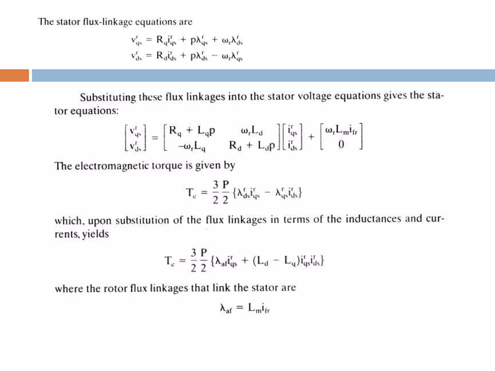
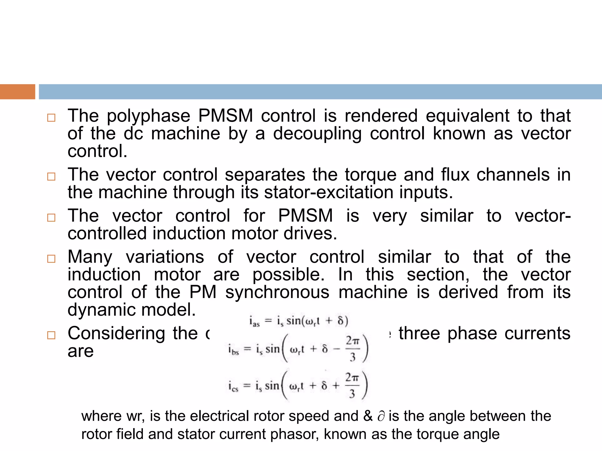
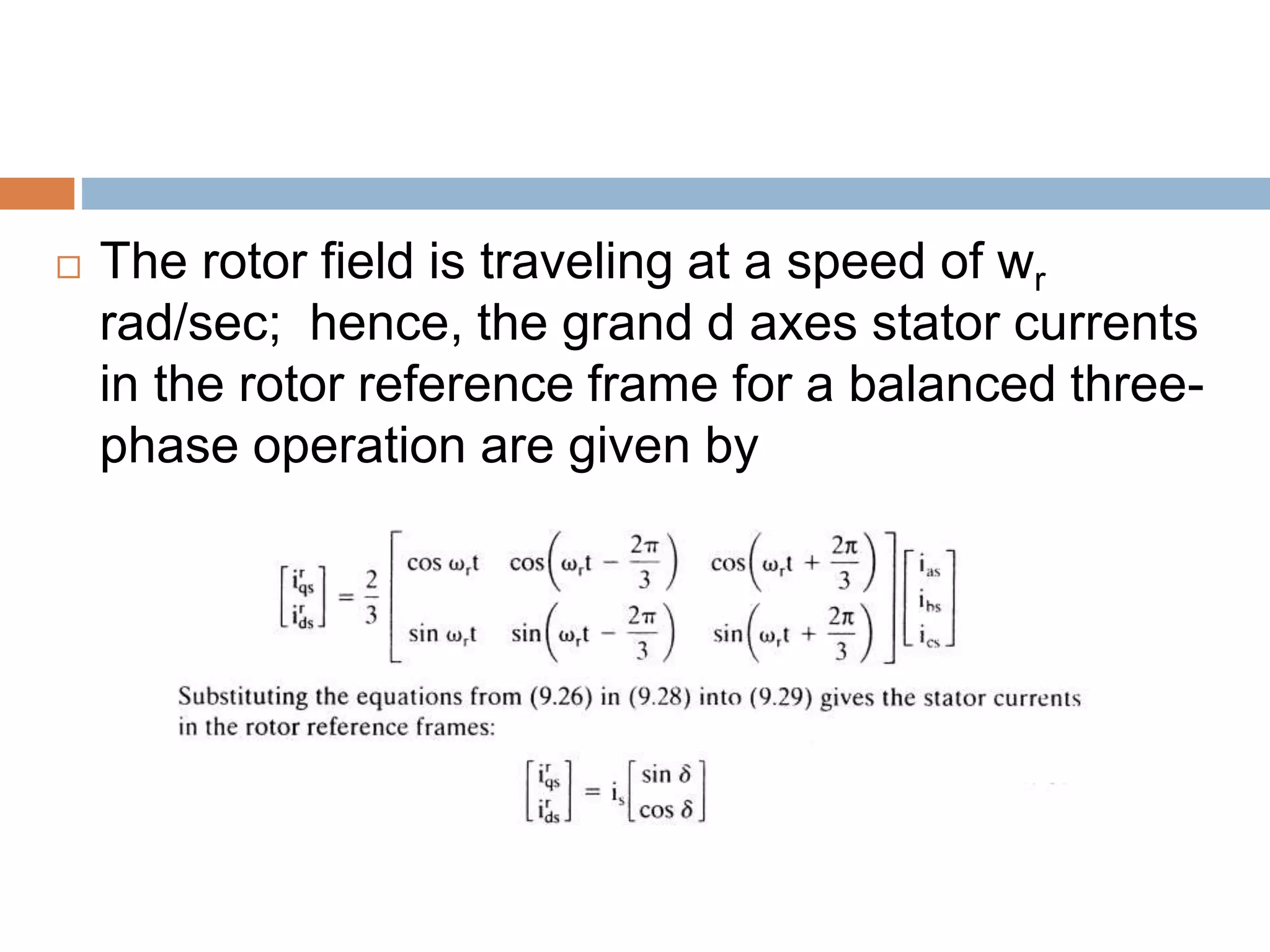
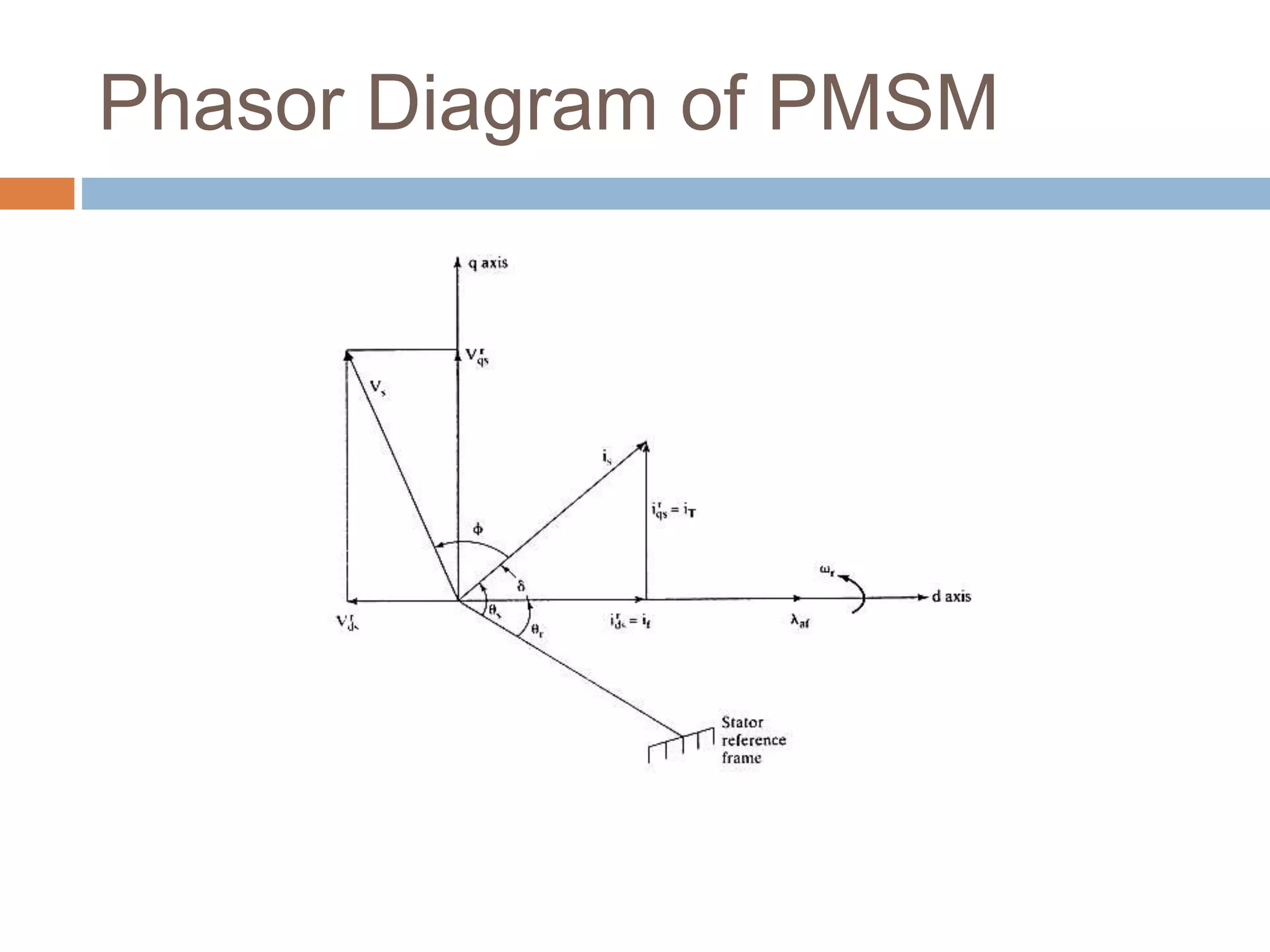
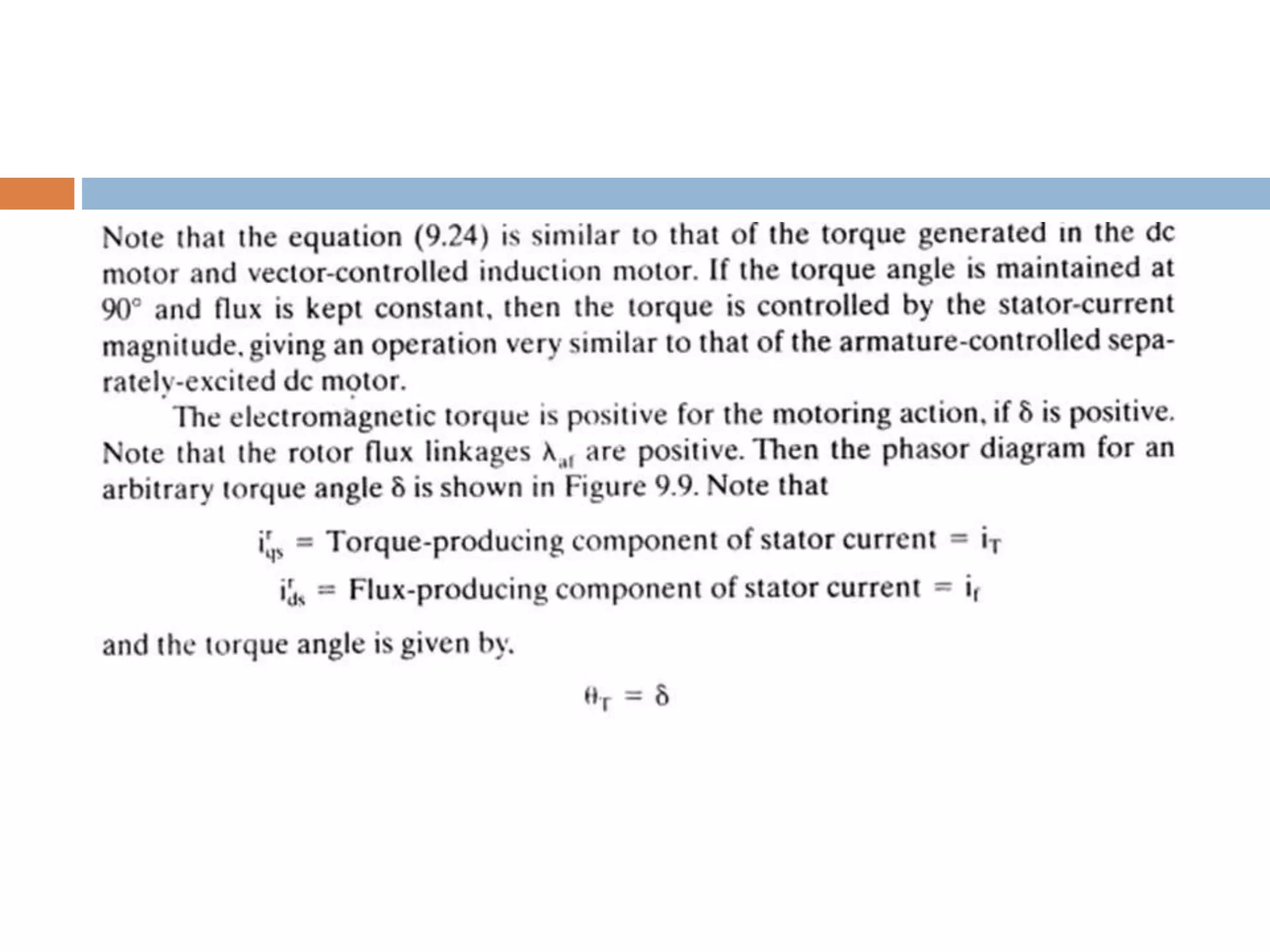
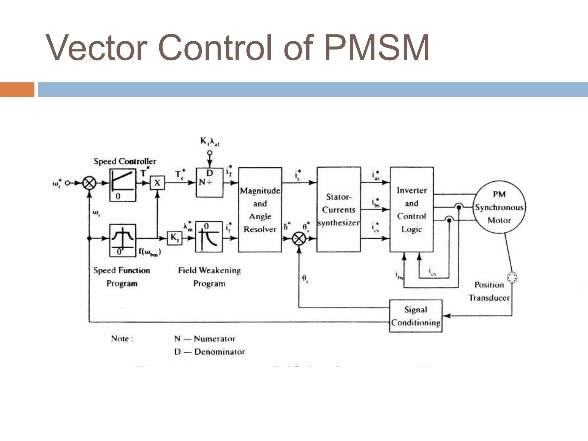
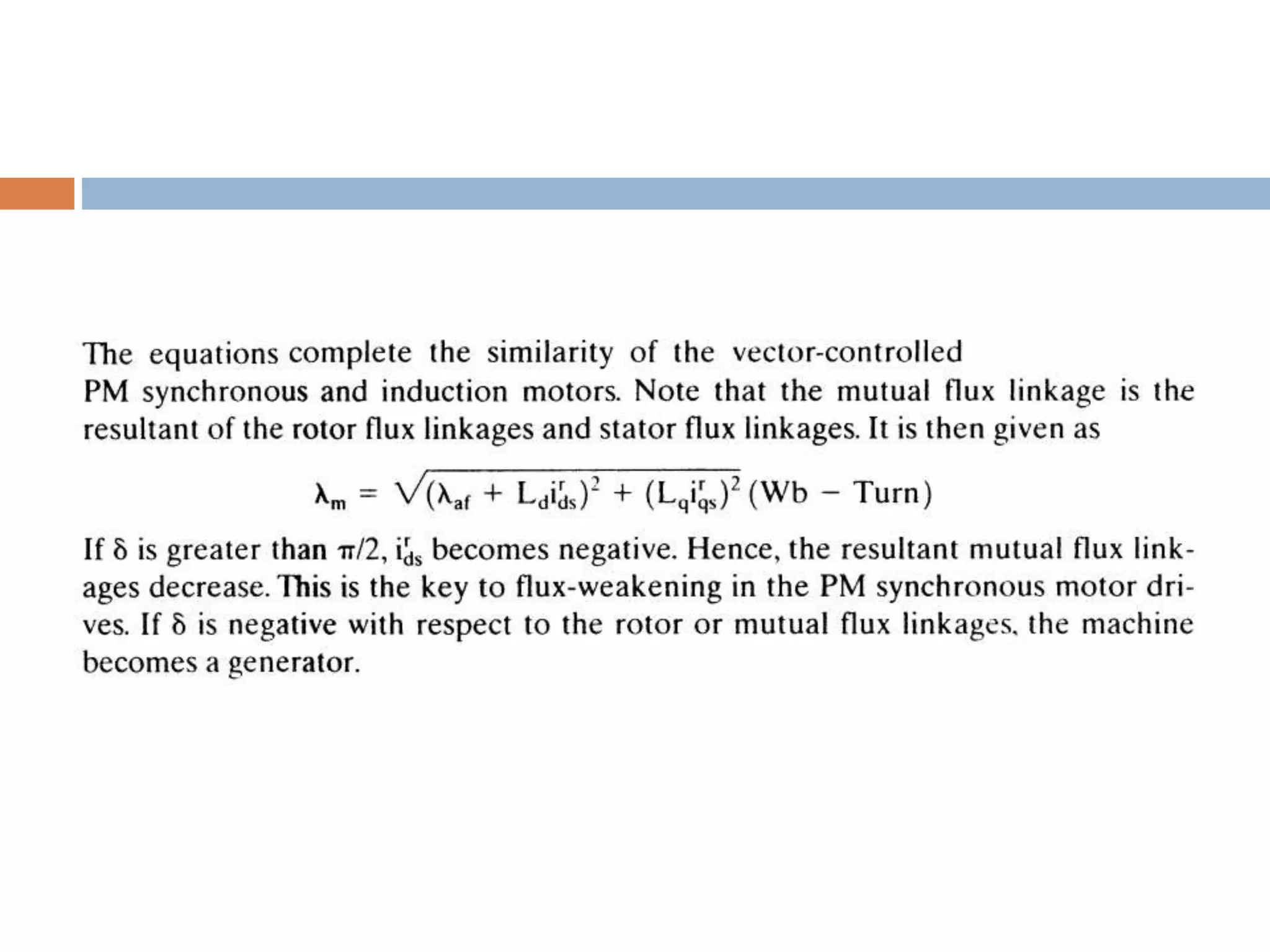
VECTOR CONTROL OF
SYNCHRONOUS
MOTOR
VECTOR CONTROL OF PM SYNCHRONOUS MACHINE
(PMSM)
 A dynamic model of the PMSM is required to
derive the vector-control algorithm to decouple
the air gap-flux and torque channels in the
drive system.
Model of the PMSM
 The two-axes PMSM stator windings can be considered to
have equal turns per phase.
 The rotor flux can be assumed to be concentrated along the d
axis while there is zero flux along the q axis, an assumption
similarly made in the derivation of indirect vector-controlled
induction motor drives.
 Further. it is assumed that the machine core losses are
negligible.
 Also, rotor flux is assumed to be constant at a given
operating point. Variations in rotor temperature alter the
magnet flux, but its variation with time is considered to be
negligible.
 There is no need to include the rotor voltage equations as in
the induction motor, since there is no external source
connected to the rotor magnets, and variation in the rotor flux
with respect to time is negligible.
 The stator equations of the induction machine in the
rotor reference frames using flux linkages are taken to
derive the model of the PMSM.
 The rotor frame of reference is chosen because the
position of the rotor magnets determines.
independently of the stator voltages and currents, the
instantaneous induced emfs and subsequently the
stator currents and torque of the machine.
 Again, this is not the case in the induction machine:
there, the rotor fluxes are not independent variables,
they are influenced by the stator voltages and
currents, and that is why any frame of reference is
suitable for the dynamic modeling of the induction
machine.
 When rotor reference frames are considered, it means the
equivalent q and d axis stator windings are transformed to the
reference frames that are revolving at rotor speed.
 The consequence is that there is zero speed differential between
the rotor and stator magnetic fields and the stator q and d axis
windings have a fixed phase relationship with the rotor magnet axis.
which is the d axis in the modeling.
where Rd and Rq are the quadrature- and direct-axis winding resistances,
which are equal (and hereafter referred to as Rs), and the q and d axes
stator flux linkages in the rotor reference frames are
 but the self-inductances of the stator q and d axes windings
are equal to Ls only when the rotor magnets have an arc of
electrical 1800.
 That hardly ever is the casein practice. This has the
implication that the reluctances along the magnet axis and
the interpolar axis are different.
 When a stator winding (say d axis) is in alignment with the
rotor magnet axis, the reluctance of the path is maximum; the
magnet reluctance is almost the same as the air gap
reluctance, and hence its inductance is the lowest at this
time.
 The inductance then is referred to as the direct-axis
inductance, Ld.
 At this time, the q axis winding faces the interpolar path in
the rotor, where the flux path encounters no magnet but only
the air gaps and iron in the rotor, resulting in lower reluctance
and higher inductance.
 The inductance of the q axis winding is Lq at this time.
 As the rotor magnets and the stator q and d axis windings are fixed
in space, that the winding inductances do not change in rotor
reference frames is to be noted.
 In order, then, to compute the stator flux linkages in the q and d
axes, the cur rents in the rotor and stator are required.
 The permanent-magnet excitation can be modeled as a constant
current source, ifr. The rotor flux is along the d axis so the d axis
rotor current is ifr.
 The q axis current in the rotor is zero, because there is no flux
along this axis in the rotor, by assumption. Then the flux linkages
are written as
where Lm is the mutual inductance between the stator winding and rotor
magnets.
 The rotor flux linkages are considered constant except for
temperature effects.
 The temperature sensitivity of the magnets reduces the
residual flux density and, hence. the flux linkages with
increasing temperature.
 The sarrarium-cobalt magnets have the least amount of
temperature sensitivity: - 2 to -3% per 100°C rise in tempera
ture.
 Neodymimum magnets have - 12 to -13% per 100°C rise in
temperature sensitivity: the ceramic magnets have -19% per
100°C rise in temperature sensitivity.
 Therefore, the temperature sensitivity of the magnets has to
be included in the dynamic simulation by appropriately
correcting for the rotor flux linkages from their nominal
values.
 The polyphase PMSM control is rendered equivalent to that
of the dc machine by a decoupling control known as vector
control.
 The vector control separates the torque and flux channels in
the machine through its stator-excitation inputs.
 The vector control for PMSM is very similar to vector-
controlled induction motor drives.
 Many variations of vector control similar to that of the
induction motor are possible. In this section, the vector
control of the PM synchronous machine is derived from its
dynamic model.
 Considering the currents as inputs. the three phase currents
are
where wr, is the electrical rotor speed and & ∂ is the angle between the
rotor field and stator current phasor, known as the torque angle
 The rotor field is traveling at a speed of wr
rad/sec; hence, the grand d axes stator currents
in the rotor reference frame for a balanced three-
phase operation are given by
 The q and d axes currents are constants in rotor reference frames, since ∂
is a constant for a given load torque.
 As these are constants, they are very similar to armature and field currents
in the separately-excited de machine.
 The q axis current is distinctly equivalent to the armature current of the de
machine: the d axis current is field current, but not in its entirety.
 It is only a partial field current: the other part is contributed by the
equivalent current source representing the permanent magnet field.
 It is discussed in detail in the section on flux weakening operation of the
PMSM.
 Substituting this equation into the electromagnetic torque expression gives
the torque:
Phasor Diagram of PMSM
Vector Control of PMSM
Vector control of pmsm

Vector control of pmsm

  • 1.
  • 2.
    VECTOR CONTROL OFPM SYNCHRONOUS MACHINE (PMSM)  A dynamic model of the PMSM is required to derive the vector-control algorithm to decouple the air gap-flux and torque channels in the drive system.
  • 3.
    Model of thePMSM  The two-axes PMSM stator windings can be considered to have equal turns per phase.  The rotor flux can be assumed to be concentrated along the d axis while there is zero flux along the q axis, an assumption similarly made in the derivation of indirect vector-controlled induction motor drives.  Further. it is assumed that the machine core losses are negligible.  Also, rotor flux is assumed to be constant at a given operating point. Variations in rotor temperature alter the magnet flux, but its variation with time is considered to be negligible.  There is no need to include the rotor voltage equations as in the induction motor, since there is no external source connected to the rotor magnets, and variation in the rotor flux with respect to time is negligible.
  • 4.
     The statorequations of the induction machine in the rotor reference frames using flux linkages are taken to derive the model of the PMSM.  The rotor frame of reference is chosen because the position of the rotor magnets determines. independently of the stator voltages and currents, the instantaneous induced emfs and subsequently the stator currents and torque of the machine.  Again, this is not the case in the induction machine: there, the rotor fluxes are not independent variables, they are influenced by the stator voltages and currents, and that is why any frame of reference is suitable for the dynamic modeling of the induction machine.
  • 5.
     When rotorreference frames are considered, it means the equivalent q and d axis stator windings are transformed to the reference frames that are revolving at rotor speed.  The consequence is that there is zero speed differential between the rotor and stator magnetic fields and the stator q and d axis windings have a fixed phase relationship with the rotor magnet axis. which is the d axis in the modeling. where Rd and Rq are the quadrature- and direct-axis winding resistances, which are equal (and hereafter referred to as Rs), and the q and d axes stator flux linkages in the rotor reference frames are
  • 6.
     but theself-inductances of the stator q and d axes windings are equal to Ls only when the rotor magnets have an arc of electrical 1800.  That hardly ever is the casein practice. This has the implication that the reluctances along the magnet axis and the interpolar axis are different.  When a stator winding (say d axis) is in alignment with the rotor magnet axis, the reluctance of the path is maximum; the magnet reluctance is almost the same as the air gap reluctance, and hence its inductance is the lowest at this time.  The inductance then is referred to as the direct-axis inductance, Ld.  At this time, the q axis winding faces the interpolar path in the rotor, where the flux path encounters no magnet but only the air gaps and iron in the rotor, resulting in lower reluctance and higher inductance.
  • 7.
     The inductanceof the q axis winding is Lq at this time.  As the rotor magnets and the stator q and d axis windings are fixed in space, that the winding inductances do not change in rotor reference frames is to be noted.  In order, then, to compute the stator flux linkages in the q and d axes, the cur rents in the rotor and stator are required.  The permanent-magnet excitation can be modeled as a constant current source, ifr. The rotor flux is along the d axis so the d axis rotor current is ifr.  The q axis current in the rotor is zero, because there is no flux along this axis in the rotor, by assumption. Then the flux linkages are written as where Lm is the mutual inductance between the stator winding and rotor magnets.
  • 9.
     The rotorflux linkages are considered constant except for temperature effects.  The temperature sensitivity of the magnets reduces the residual flux density and, hence. the flux linkages with increasing temperature.  The sarrarium-cobalt magnets have the least amount of temperature sensitivity: - 2 to -3% per 100°C rise in tempera ture.  Neodymimum magnets have - 12 to -13% per 100°C rise in temperature sensitivity: the ceramic magnets have -19% per 100°C rise in temperature sensitivity.  Therefore, the temperature sensitivity of the magnets has to be included in the dynamic simulation by appropriately correcting for the rotor flux linkages from their nominal values.
  • 10.
     The polyphasePMSM control is rendered equivalent to that of the dc machine by a decoupling control known as vector control.  The vector control separates the torque and flux channels in the machine through its stator-excitation inputs.  The vector control for PMSM is very similar to vector- controlled induction motor drives.  Many variations of vector control similar to that of the induction motor are possible. In this section, the vector control of the PM synchronous machine is derived from its dynamic model.  Considering the currents as inputs. the three phase currents are where wr, is the electrical rotor speed and & ∂ is the angle between the rotor field and stator current phasor, known as the torque angle
  • 11.
     The rotorfield is traveling at a speed of wr rad/sec; hence, the grand d axes stator currents in the rotor reference frame for a balanced three- phase operation are given by
  • 12.
     The qand d axes currents are constants in rotor reference frames, since ∂ is a constant for a given load torque.  As these are constants, they are very similar to armature and field currents in the separately-excited de machine.  The q axis current is distinctly equivalent to the armature current of the de machine: the d axis current is field current, but not in its entirety.  It is only a partial field current: the other part is contributed by the equivalent current source representing the permanent magnet field.  It is discussed in detail in the section on flux weakening operation of the PMSM.  Substituting this equation into the electromagnetic torque expression gives the torque:
  • 13.
  • 15.