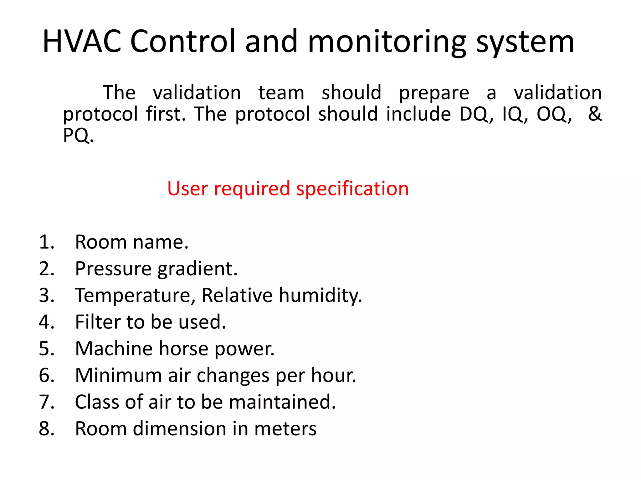
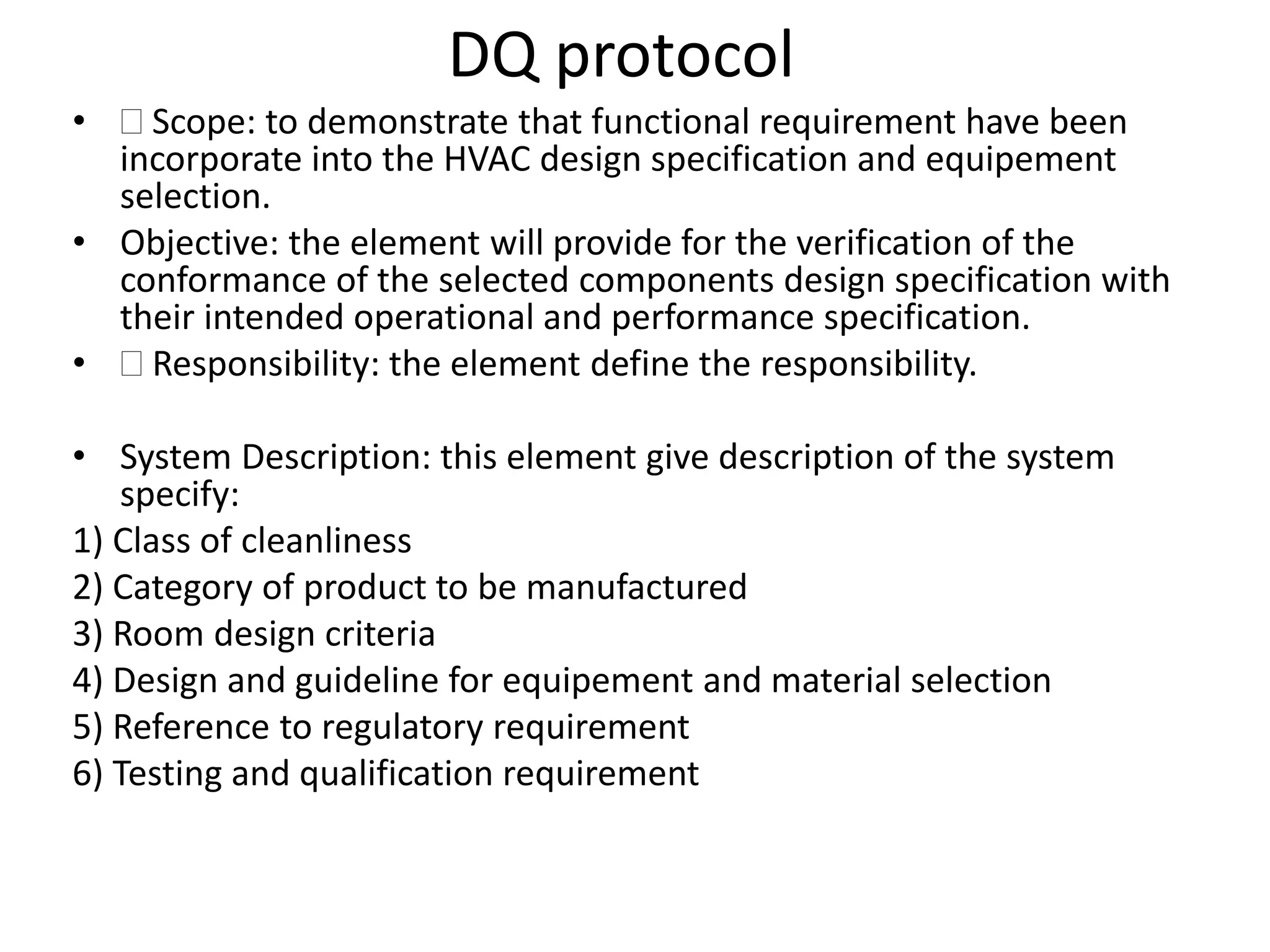
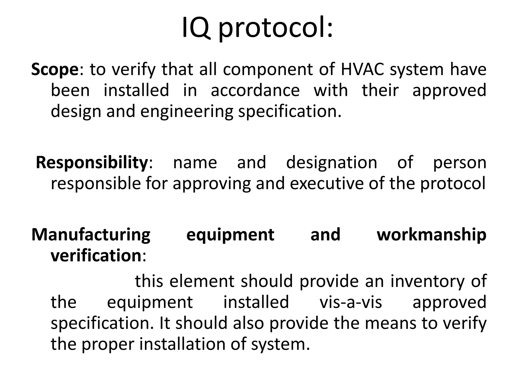
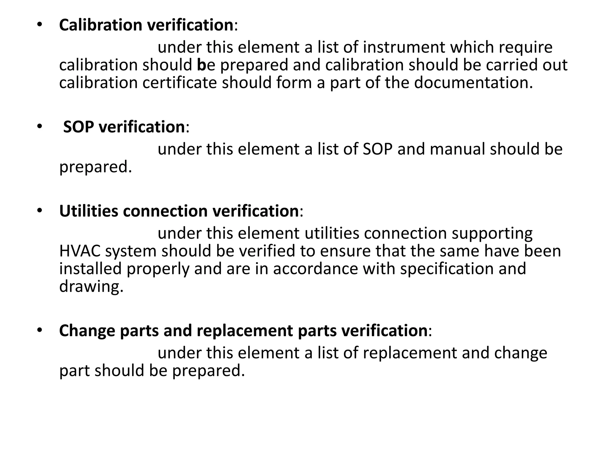
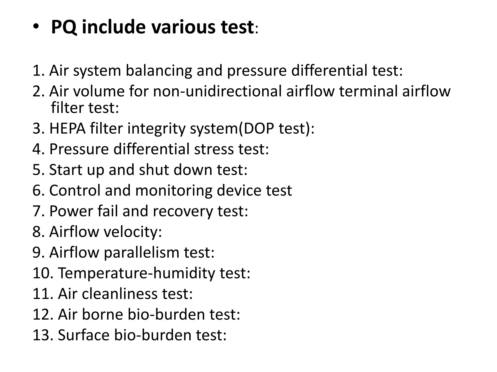
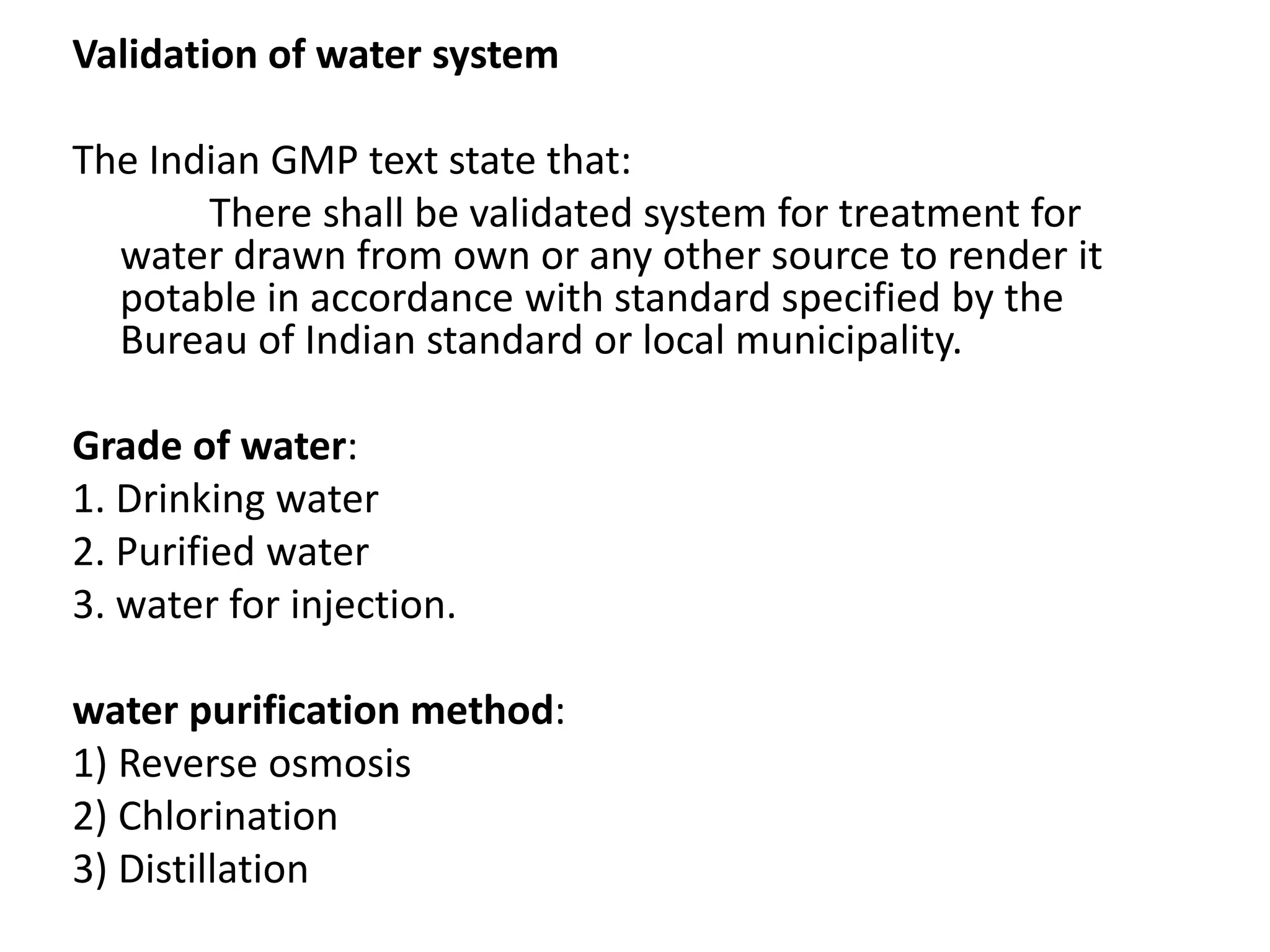
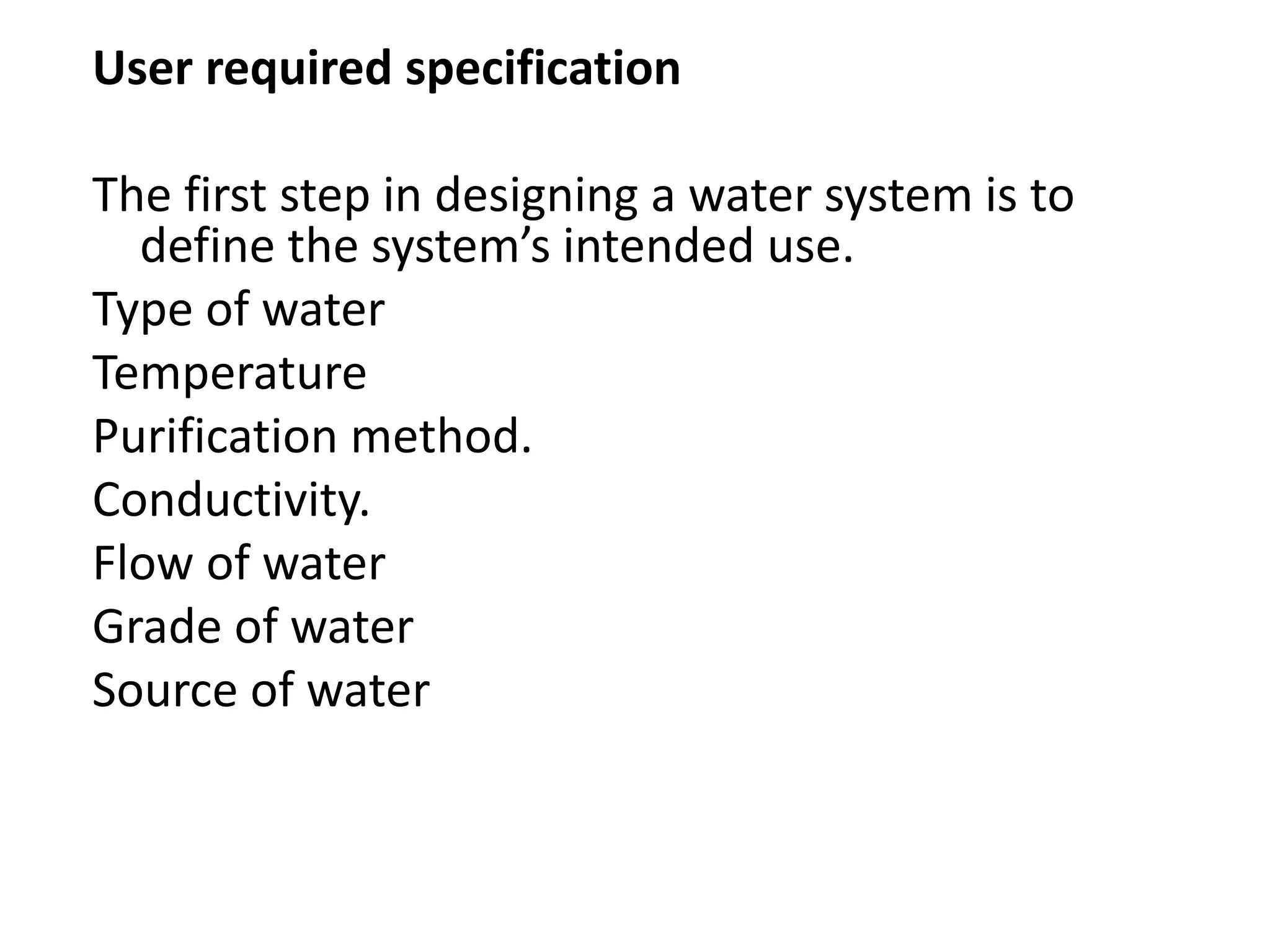
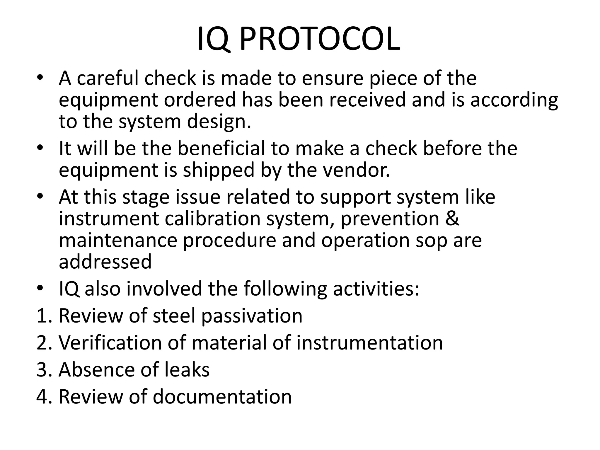
Validation utility system
Arpit Rajaram Suralkar
M Pharmacy (Quality Assurance)
Validation Of Utility System
• The use of critical utility systems in the pharmaceutical
industry is very important to final product quality.
• Critical utilities found in pharmaceutical, medical device,
and biotechnology production facilities usually support
various equipment and processes.
• These utilities must meet both quantitative and qualitative
specifications.
• These utilities must meet both quantitative and qualitative
specifications.
• The critical utilities that been used:
1. Water systems
2. Clean steam system
3. Heating Ventilation and Air Conditioning (HVAC) systems
4. Process gases
Why is Utility System Quality
Important in Pharmaceuticals?
• All pharmaceutical manufacturing facilities
need to adhere strictly to FDA-approved
regulations
• CGMP requirements can be useful in ensuring
the efficacy, quality and safety of product,
.
VALIDATION OF HVAC SYSTEM
• Heating, ventilation and air conditioning system are used
in the pharmaceutical plant to prevent contamination and
to provide comfortable working conditioning.
• Environmental parameter like conc. of airborne nonviable
and viable particulate matter, chemical and gaseous
material can affect the quality of finished product.
• The product quality can also be affected although to a
lesser extent by vibration, lighting and other radiation.
• Ambient air may have different contaminant the most
common being the dust. Dust can be roughly classify by
size:
• a) Coarse dust(particle size 50-500µ)
• b) Fine dust(particle size 1-50µ)
• c) Ultra fine dust (particle size 0.5-1.0µ)
HVAC Control and monitoring system
The validation team should prepare a validation
protocol first. The protocol should include DQ, IQ, OQ, &
PQ.
User required specification
1. Room name.
2. Pressure gradient.
3. Temperature, Relative humidity.
4. Filter to be used.
5. Machine horse power.
6. Minimum air changes per hour.
7. Class of air to be maintained.
8. Room dimension in meters
DQ protocol
•  Scope: to demonstrate that functional requirement have been
incorporate into the HVAC design specification and equipement
selection.
• Objective: the element will provide for the verification of the
conformance of the selected components design specification with
their intended operational and performance specification.
•  Responsibility: the element define the responsibility.
• System Description: this element give description of the system
specify:
1) Class of cleanliness
2) Category of product to be manufactured
3) Room design criteria
4) Design and guideline for equipement and material selection
5) Reference to regulatory requirement
6) Testing and qualification requirement
IQ protocol:
Scope: to verify that all component of HVAC system have
been installed in accordance with their approved
design and engineering specification.
Responsibility: name and designation of person
responsible for approving and executive of the protocol
Manufacturing equipment and workmanship
verification:
this element should provide an inventory of
the equipment installed vis-a-vis approved
specification. It should also provide the means to verify
the proper installation of system.
• Calibration verification:
under this element a list of instrument which require
calibration should be prepared and calibration should be carried out
calibration certificate should form a part of the documentation.
• SOP verification:
under this element a list of SOP and manual should be
prepared.
• Utilities connection verification:
under this element utilities connection supporting
HVAC system should be verified to ensure that the same have been
installed properly and are in accordance with specification and
drawing.
• Change parts and replacement parts verification:
under this element a list of replacement and change
part should be prepared.
• Maintenance procedure verification:
under this element it should be ensure
that a maintenance program exist as
recommended by the manufacturer.
• Lubricant verification:
under this element it should be ensure
that only approved lubricant have been used and
these do not come in contact with supply air.
• As built drawing listing & verification:
many time there are difference
between original drawing and as built drawing .
As built drawing is the drawing which has been
physically verified through inspection, signed and
dated by the person performing inspection
OQ protocol
• Objective: to verify that given component of
HVAC system operate as specified and are in
agreement with acceptance criteria fixed for the
system parameter.
• Responsibility: names and designation of person
who are responsible for approval and execution
of protocol.
• System description: under this element a brief
description of how the system operates and
sequence of control should be given.
• Instrumental calibration: under this element it should
be verified that all the instrumentation specified have
been installed and are in calibrated system.
• equipment calibration verification: certain instrument
might be required to verify operation of the system.
• SOP verification: under this element verification of all
SOP required operation system should be verified. If
SOP is under draft stage, it should be finalized.
• OQ test: these include a series of tests designed to
prove proper operation of HVAC system;
1) Air system balancing
2) HEPA filter integrity system
3) Pressure differential stress test.
4) Airflow velocity and uniformity system
PQ protocol
• The PQ protocol is similar to OQ protocol. In the PQ the
HVAC system is assessed for its performance with in
the area it serving.
• Data is collecting under static conditions as well as
under dynamic condition by stimulating the process or
actually carrying the process.
• The test that may be carried out during the PQ include;
1. Temperature-humidity control test.
2. Air cleanliness test.
3. Airborne bio-burden test.
4. Surface bio-burden test.
• PQ include various test:
1. Air system balancing and pressure differential test:
2. Air volume for non-unidirectional airflow terminal airflow
filter test:
3. HEPA filter integrity system(DOP test):
4. Pressure differential stress test:
5. Start up and shut down test:
6. Control and monitoring device test
7. Power fail and recovery test:
8. Airflow velocity:
9. Airflow parallelism test:
10. Temperature-humidity test:
11. Air cleanliness test:
12. Air borne bio-burden test:
13. Surface bio-burden test:
Validation of water system
The Indian GMP text state that:
There shall be validated system for treatment for
water drawn from own or any other source to render it
potable in accordance with standard specified by the
Bureau of Indian standard or local municipality.
Grade of water:
1. Drinking water
2. Purified water
3. water for injection.
water purification method:
1) Reverse osmosis
2) Chlorination
3) Distillation
User required specification
The first step in designing a water system is to
define the system’s intended use.
Type of water
Temperature
Purification method.
Conductivity.
Flow of water
Grade of water
Source of water
IQ PROTOCOL
• A careful check is made to ensure piece of the
equipment ordered has been received and is according
to the system design.
• It will be the beneficial to make a check before the
equipment is shipped by the vendor.
• At this stage issue related to support system like
instrument calibration system, prevention &
maintenance procedure and operation sop are
addressed
• IQ also involved the following activities:
1. Review of steel passivation
2. Verification of material of instrumentation
3. Absence of leaks
4. Review of documentation
OQ protocol:
•  OQ verifies the capability of the processing until that they
perform satisfactory within the operation limit
• The focus of the OQ is to define the critical item and practices e.g.
alarm conditions for utilities such as low stem pressure, differential
pressure limit, conductivity limit.
• calibration need are assesed and calibration are carried out
• Documented procedure are also developed fir the maintainance,
adjustments, monitoring and control of the equipement involved.
.
• Limites within which the plant will operate should be specified.
• The OQ protocol provide a functional testing of the system
component.
• PQ protocol:
Phase 1:
During the phase a test period of 2-4 weeks
should be spent monitoring the system. The system
should operate contineously without failure or
performance deviation. T include;
1. Sampling of the incoming feed water daily to verify its
quality.
2. 2. Sampling after each step in psurification process
daily.
3. 3. Finalization of operating ranges.
4. 4. Verification of provisional alert.
5. 5. Finalization of operation, sanitization, cleaning and
maintainance procedure.
6. 6. Testing of water for each microbiological and
chemical testing as per plan.
• Phase 2:
• After complition of phase1 a further period of 2-4 week should be
spent on monitoring the water system. the sampling system might
remain the same as in the phase1.
• This approach should demonstrate the following:
1. The water system operate consistency.
2. The water system produce and delivared constantly the require
quality of water in require quality.
• Phase 3:
• Usually run of 1 year after the succesfull complition of phase 2.
water can be used for manufacturing purpose during the phase.
• The phase has the following objective:
1. To demonstrate reliable performing in long run .
2. To evaluate seasonal variation in feed water.
3. To reduce sample location.
VALIDATION STEAM SYSTEM
There are 2 type of steam system in pharmaceutical industry.
The system which is called house steam. Consist of steam generator and
distribustion system made up of iron or steel.
The second type of system called as clean steam estabilished when steam is
used for directly treating the product or product contact surface.
Distribution line in both plant and clean steam are insulted to reduce heat
and to provide safety.
Approach of steam system validation include the following step:
1. Make a process diagram and identify major step.
2. Define major equipment process.
3. Carry out IQ & OQ.
4. Carry out PQ
• IQ protocol:
• Clean steam generator:
1. Conform the checklist according to purchase
specification
2. Connect the generator to the required utilities.
3. Tighten flanges or other fiting clean generator
chemically and passivate generator after
installation.
4. Carry out pressure testing and result record.
5. Check and calibrate all critical process intrument. If
calibration of any instrument can not be done by
internal staff, engage an external agency.
Distribuion system:
1. Conform that material of construction of
distribution system is as per the specification
of the company.
2. Compare the design drawing and the as built
drawing and make note of modification
carried out in the design drawing at the time
of construction.
3. Clean the distribution system efoe start up
and record it.
4. Carry out the pressure test and record the
result
• OQ protocol:
• Test all the point of the system for adequate
supply of the steam under maximum load or
other production conditions. If there is limitation
of use of only a few use point at time these
conditions should be tested as worst case
condition.
• Quality of steam should be tested ay all the use
point.
• Use point should be tested to find out that excess
condensate is not present under operation
condition
• If it is found excess condensate is present, it
should be removed by additional traps or other
suitable means.
• PQ protocol
• The PQ consist of the required testing
specified in protocol.
• A typical protocol would include several test
under defined load conditions.
• testing consist of conditioning steam at
various use point and subject condensate to
testing for WFI.

Validation utility system

  • 1.
    Validation utility system ArpitRajaram Suralkar M Pharmacy (Quality Assurance)
  • 2.
    Validation Of UtilitySystem • The use of critical utility systems in the pharmaceutical industry is very important to final product quality. • Critical utilities found in pharmaceutical, medical device, and biotechnology production facilities usually support various equipment and processes. • These utilities must meet both quantitative and qualitative specifications. • These utilities must meet both quantitative and qualitative specifications. • The critical utilities that been used: 1. Water systems 2. Clean steam system 3. Heating Ventilation and Air Conditioning (HVAC) systems 4. Process gases
  • 3.
    Why is UtilitySystem Quality Important in Pharmaceuticals? • All pharmaceutical manufacturing facilities need to adhere strictly to FDA-approved regulations • CGMP requirements can be useful in ensuring the efficacy, quality and safety of product, .
  • 4.
    VALIDATION OF HVACSYSTEM • Heating, ventilation and air conditioning system are used in the pharmaceutical plant to prevent contamination and to provide comfortable working conditioning. • Environmental parameter like conc. of airborne nonviable and viable particulate matter, chemical and gaseous material can affect the quality of finished product. • The product quality can also be affected although to a lesser extent by vibration, lighting and other radiation. • Ambient air may have different contaminant the most common being the dust. Dust can be roughly classify by size: • a) Coarse dust(particle size 50-500µ) • b) Fine dust(particle size 1-50µ) • c) Ultra fine dust (particle size 0.5-1.0µ)
  • 5.
    HVAC Control andmonitoring system The validation team should prepare a validation protocol first. The protocol should include DQ, IQ, OQ, & PQ. User required specification 1. Room name. 2. Pressure gradient. 3. Temperature, Relative humidity. 4. Filter to be used. 5. Machine horse power. 6. Minimum air changes per hour. 7. Class of air to be maintained. 8. Room dimension in meters
  • 6.
    DQ protocol • Scope: to demonstrate that functional requirement have been incorporate into the HVAC design specification and equipement selection. • Objective: the element will provide for the verification of the conformance of the selected components design specification with their intended operational and performance specification. •  Responsibility: the element define the responsibility. • System Description: this element give description of the system specify: 1) Class of cleanliness 2) Category of product to be manufactured 3) Room design criteria 4) Design and guideline for equipement and material selection 5) Reference to regulatory requirement 6) Testing and qualification requirement
  • 7.
    IQ protocol: Scope: toverify that all component of HVAC system have been installed in accordance with their approved design and engineering specification. Responsibility: name and designation of person responsible for approving and executive of the protocol Manufacturing equipment and workmanship verification: this element should provide an inventory of the equipment installed vis-a-vis approved specification. It should also provide the means to verify the proper installation of system.
  • 8.
    • Calibration verification: underthis element a list of instrument which require calibration should be prepared and calibration should be carried out calibration certificate should form a part of the documentation. • SOP verification: under this element a list of SOP and manual should be prepared. • Utilities connection verification: under this element utilities connection supporting HVAC system should be verified to ensure that the same have been installed properly and are in accordance with specification and drawing. • Change parts and replacement parts verification: under this element a list of replacement and change part should be prepared.
  • 9.
    • Maintenance procedureverification: under this element it should be ensure that a maintenance program exist as recommended by the manufacturer. • Lubricant verification: under this element it should be ensure that only approved lubricant have been used and these do not come in contact with supply air. • As built drawing listing & verification: many time there are difference between original drawing and as built drawing . As built drawing is the drawing which has been physically verified through inspection, signed and dated by the person performing inspection
  • 10.
    OQ protocol • Objective:to verify that given component of HVAC system operate as specified and are in agreement with acceptance criteria fixed for the system parameter. • Responsibility: names and designation of person who are responsible for approval and execution of protocol. • System description: under this element a brief description of how the system operates and sequence of control should be given.
  • 11.
    • Instrumental calibration:under this element it should be verified that all the instrumentation specified have been installed and are in calibrated system. • equipment calibration verification: certain instrument might be required to verify operation of the system. • SOP verification: under this element verification of all SOP required operation system should be verified. If SOP is under draft stage, it should be finalized. • OQ test: these include a series of tests designed to prove proper operation of HVAC system; 1) Air system balancing 2) HEPA filter integrity system 3) Pressure differential stress test. 4) Airflow velocity and uniformity system
  • 12.
    PQ protocol • ThePQ protocol is similar to OQ protocol. In the PQ the HVAC system is assessed for its performance with in the area it serving. • Data is collecting under static conditions as well as under dynamic condition by stimulating the process or actually carrying the process. • The test that may be carried out during the PQ include; 1. Temperature-humidity control test. 2. Air cleanliness test. 3. Airborne bio-burden test. 4. Surface bio-burden test.
  • 13.
    • PQ includevarious test: 1. Air system balancing and pressure differential test: 2. Air volume for non-unidirectional airflow terminal airflow filter test: 3. HEPA filter integrity system(DOP test): 4. Pressure differential stress test: 5. Start up and shut down test: 6. Control and monitoring device test 7. Power fail and recovery test: 8. Airflow velocity: 9. Airflow parallelism test: 10. Temperature-humidity test: 11. Air cleanliness test: 12. Air borne bio-burden test: 13. Surface bio-burden test:
  • 14.
    Validation of watersystem The Indian GMP text state that: There shall be validated system for treatment for water drawn from own or any other source to render it potable in accordance with standard specified by the Bureau of Indian standard or local municipality. Grade of water: 1. Drinking water 2. Purified water 3. water for injection. water purification method: 1) Reverse osmosis 2) Chlorination 3) Distillation
  • 15.
    User required specification Thefirst step in designing a water system is to define the system’s intended use. Type of water Temperature Purification method. Conductivity. Flow of water Grade of water Source of water
  • 16.
    IQ PROTOCOL • Acareful check is made to ensure piece of the equipment ordered has been received and is according to the system design. • It will be the beneficial to make a check before the equipment is shipped by the vendor. • At this stage issue related to support system like instrument calibration system, prevention & maintenance procedure and operation sop are addressed • IQ also involved the following activities: 1. Review of steel passivation 2. Verification of material of instrumentation 3. Absence of leaks 4. Review of documentation
  • 17.
    OQ protocol: • OQ verifies the capability of the processing until that they perform satisfactory within the operation limit • The focus of the OQ is to define the critical item and practices e.g. alarm conditions for utilities such as low stem pressure, differential pressure limit, conductivity limit. • calibration need are assesed and calibration are carried out • Documented procedure are also developed fir the maintainance, adjustments, monitoring and control of the equipement involved. . • Limites within which the plant will operate should be specified. • The OQ protocol provide a functional testing of the system component.
  • 18.
    • PQ protocol: Phase1: During the phase a test period of 2-4 weeks should be spent monitoring the system. The system should operate contineously without failure or performance deviation. T include; 1. Sampling of the incoming feed water daily to verify its quality. 2. 2. Sampling after each step in psurification process daily. 3. 3. Finalization of operating ranges. 4. 4. Verification of provisional alert. 5. 5. Finalization of operation, sanitization, cleaning and maintainance procedure. 6. 6. Testing of water for each microbiological and chemical testing as per plan.
  • 19.
    • Phase 2: •After complition of phase1 a further period of 2-4 week should be spent on monitoring the water system. the sampling system might remain the same as in the phase1. • This approach should demonstrate the following: 1. The water system operate consistency. 2. The water system produce and delivared constantly the require quality of water in require quality. • Phase 3: • Usually run of 1 year after the succesfull complition of phase 2. water can be used for manufacturing purpose during the phase. • The phase has the following objective: 1. To demonstrate reliable performing in long run . 2. To evaluate seasonal variation in feed water. 3. To reduce sample location.
  • 20.
    VALIDATION STEAM SYSTEM Thereare 2 type of steam system in pharmaceutical industry. The system which is called house steam. Consist of steam generator and distribustion system made up of iron or steel. The second type of system called as clean steam estabilished when steam is used for directly treating the product or product contact surface. Distribution line in both plant and clean steam are insulted to reduce heat and to provide safety. Approach of steam system validation include the following step: 1. Make a process diagram and identify major step. 2. Define major equipment process. 3. Carry out IQ & OQ. 4. Carry out PQ
  • 21.
    • IQ protocol: •Clean steam generator: 1. Conform the checklist according to purchase specification 2. Connect the generator to the required utilities. 3. Tighten flanges or other fiting clean generator chemically and passivate generator after installation. 4. Carry out pressure testing and result record. 5. Check and calibrate all critical process intrument. If calibration of any instrument can not be done by internal staff, engage an external agency.
  • 22.
    Distribuion system: 1. Conformthat material of construction of distribution system is as per the specification of the company. 2. Compare the design drawing and the as built drawing and make note of modification carried out in the design drawing at the time of construction. 3. Clean the distribution system efoe start up and record it. 4. Carry out the pressure test and record the result
  • 23.
    • OQ protocol: •Test all the point of the system for adequate supply of the steam under maximum load or other production conditions. If there is limitation of use of only a few use point at time these conditions should be tested as worst case condition. • Quality of steam should be tested ay all the use point. • Use point should be tested to find out that excess condensate is not present under operation condition • If it is found excess condensate is present, it should be removed by additional traps or other suitable means.
  • 24.
    • PQ protocol •The PQ consist of the required testing specified in protocol. • A typical protocol would include several test under defined load conditions. • testing consist of conditioning steam at various use point and subject condensate to testing for WFI.