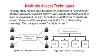
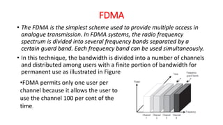
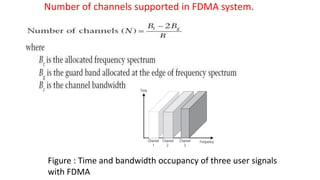
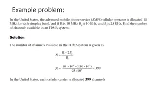
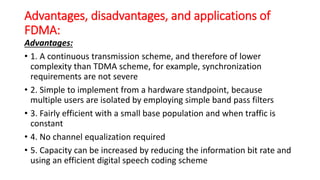
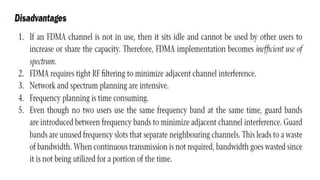
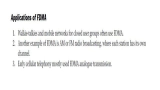
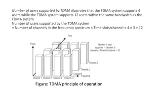
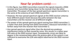
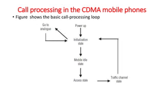
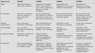
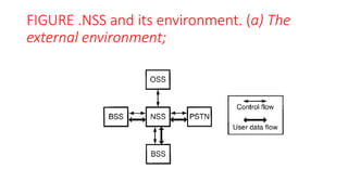
The document discusses various multiple access techniques used in wireless communication systems to allow multiple users to access a shared radio channel simultaneously. It describes Frequency Division Multiple Access (FDMA), Time Division Multiple Access (TDMA), Code Division Multiple Access (CDMA), and Space Division Multiple Access (SDMA). FDMA divides the bandwidth into different frequency channels. TDMA divides the time dimension into different time slots. CDMA uses unique codes to identify users within the same frequency band. SDMA enables spatial separation of users within the same frequency and time. The document provides details on the principles, advantages, and disadvantages of each multiple access technique.

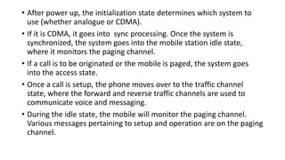
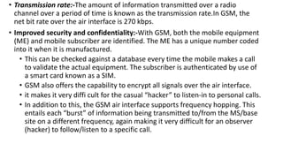
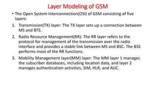
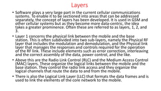
![• 3. Uplink common channels: The random-access channel (RACH) is
the only common uplink channel. RACH is the channel that the
mobile station chooses to access the calls.
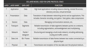
• There are two rates: RACH/F (full rate, one time slot every 8 BP), and
RACH/H (half rate, using 23 time slots in the 51 × 8 BP cycle, where 8
BP cycle [i.e. a frame] is 4.615ms).
• 4. Signaling channels: All the signaling channels have chosen one of
the physical channels,and the logical channels names are based on
their logical functions:
• 5. Slow Associated Control Channel (SACCH): A slow-rate TCH used
for signaling transport and used for non urgent procedures, mainly
handover decisions. It uses one-eighth rate. The TCH/F is always
allocated with SACCH. This combined TCH and SACCH is denoted
TACH/F.](https://image.slidesharecdn.com/vunit1-231009065843-6bc2a2fa/85/v-unit-1-pptx-66-320.jpg)
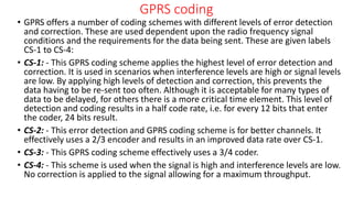
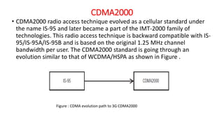
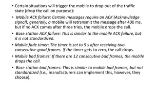
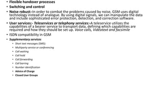
![3G Systems
• 3G mobile systems offer high bit rate services, high-quality videos,
images, and fast web access. They differ significantly from the 2G
technologies (global system for mobile communication [GSM] and
CDMA1). The aim of 3G is to provide communication services from
person to person at any place and at any time through any medium
using a compact lightweight terminal with guaranteed quality of
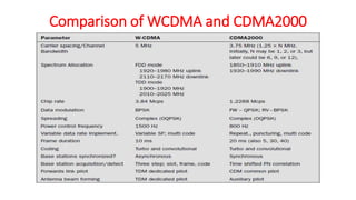
service (QoS) and security. The two standards of 3G technology that
are most popular in the world are
• Wideband code division multiple access (WCDMA)
• Code division multiple access 2000 (CDMA2000).](https://image.slidesharecdn.com/vunit1-231009065843-6bc2a2fa/85/v-unit-1-pptx-91-320.jpg)