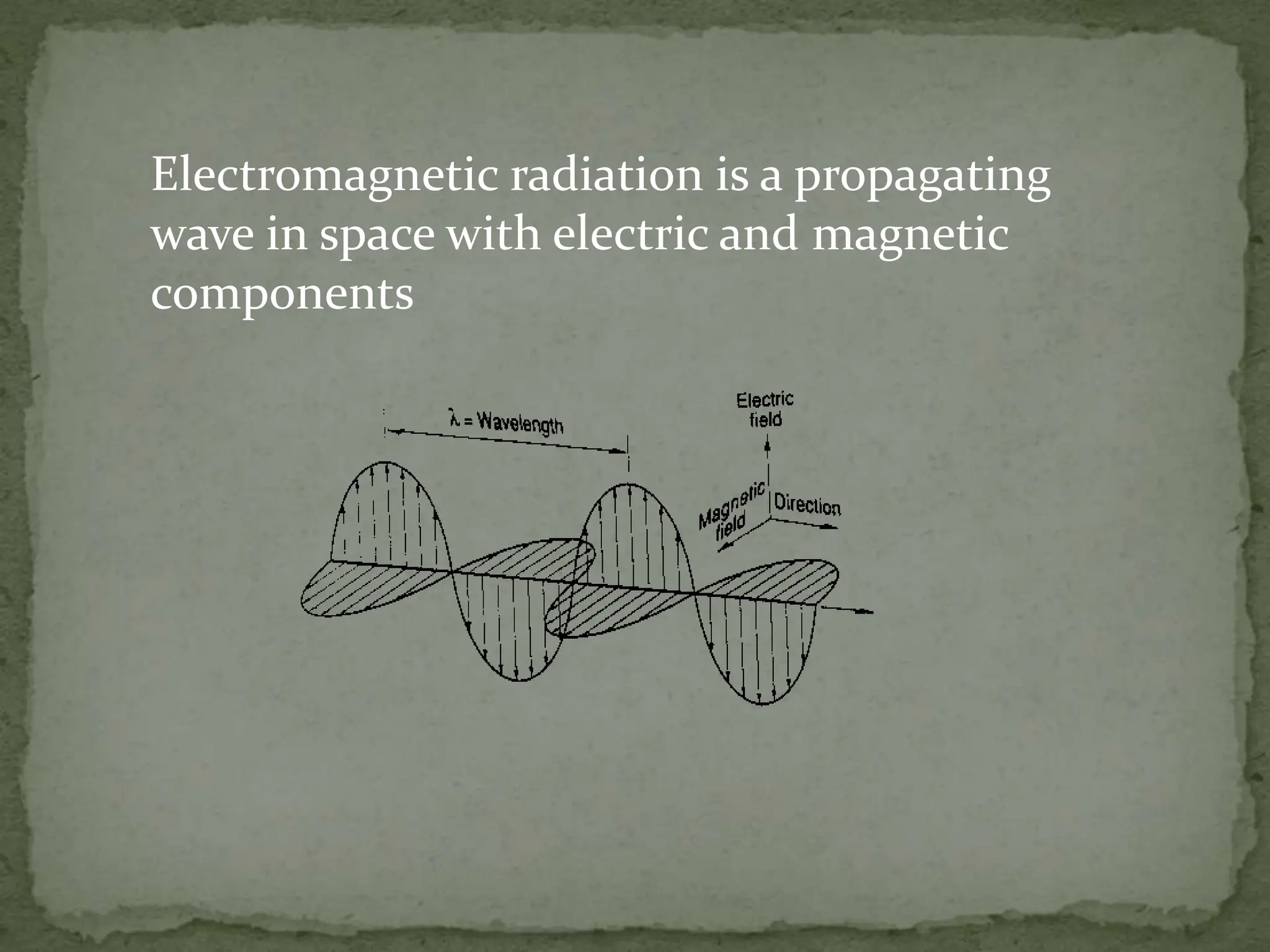
Light interacting with matter as an
analytical tool
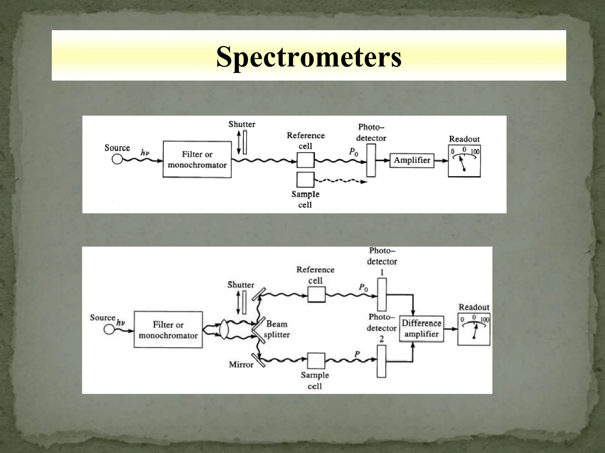
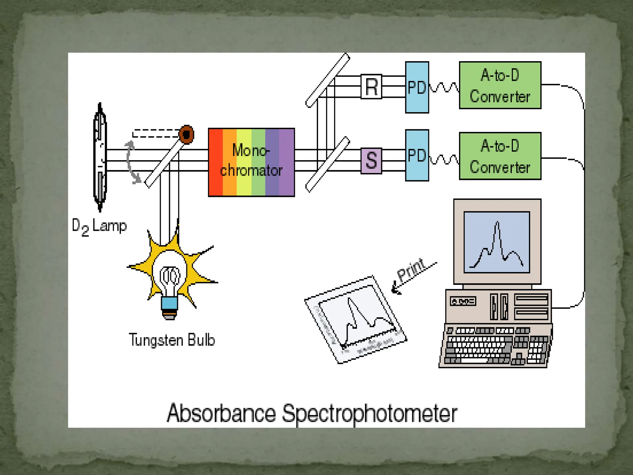
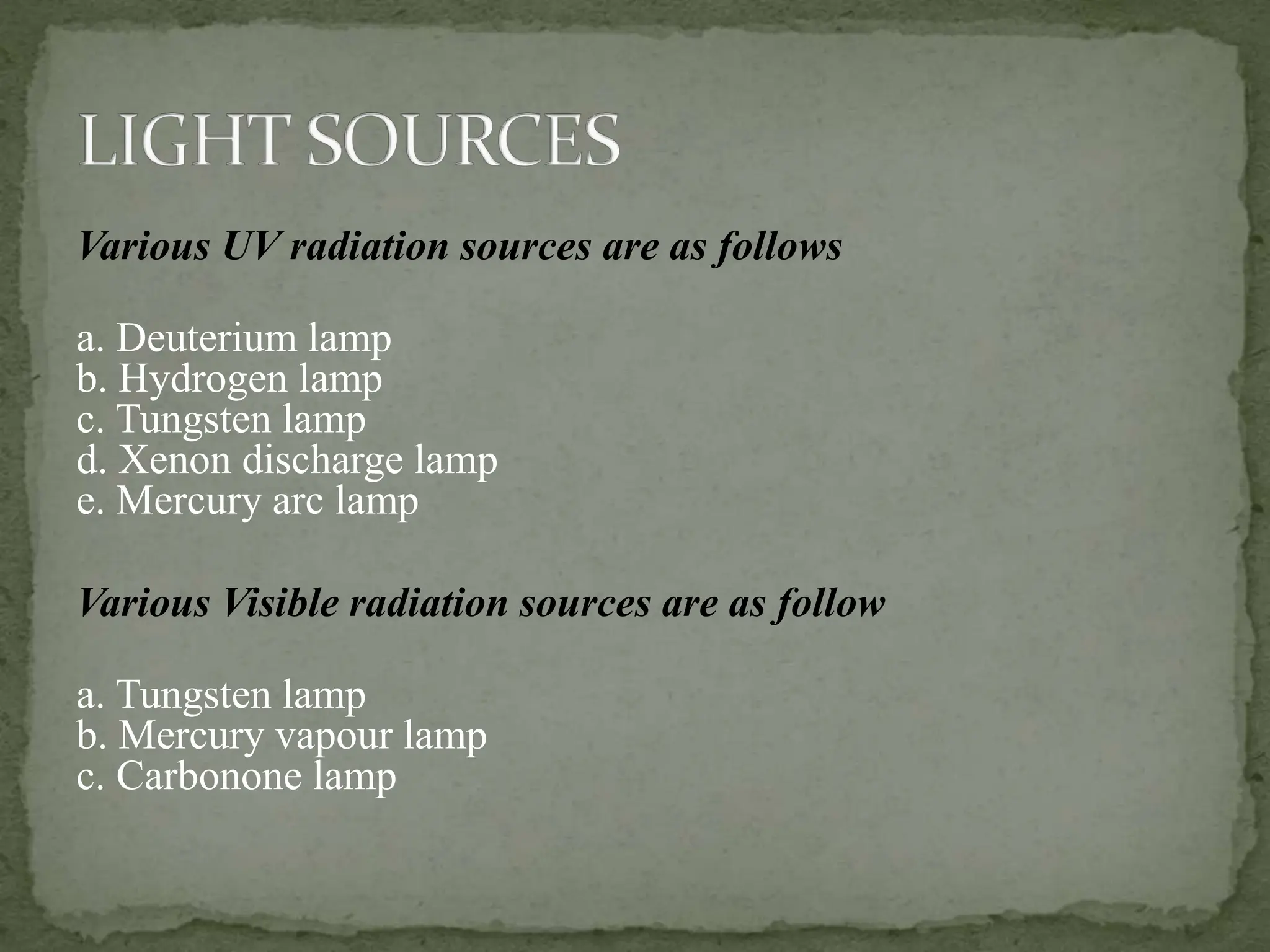
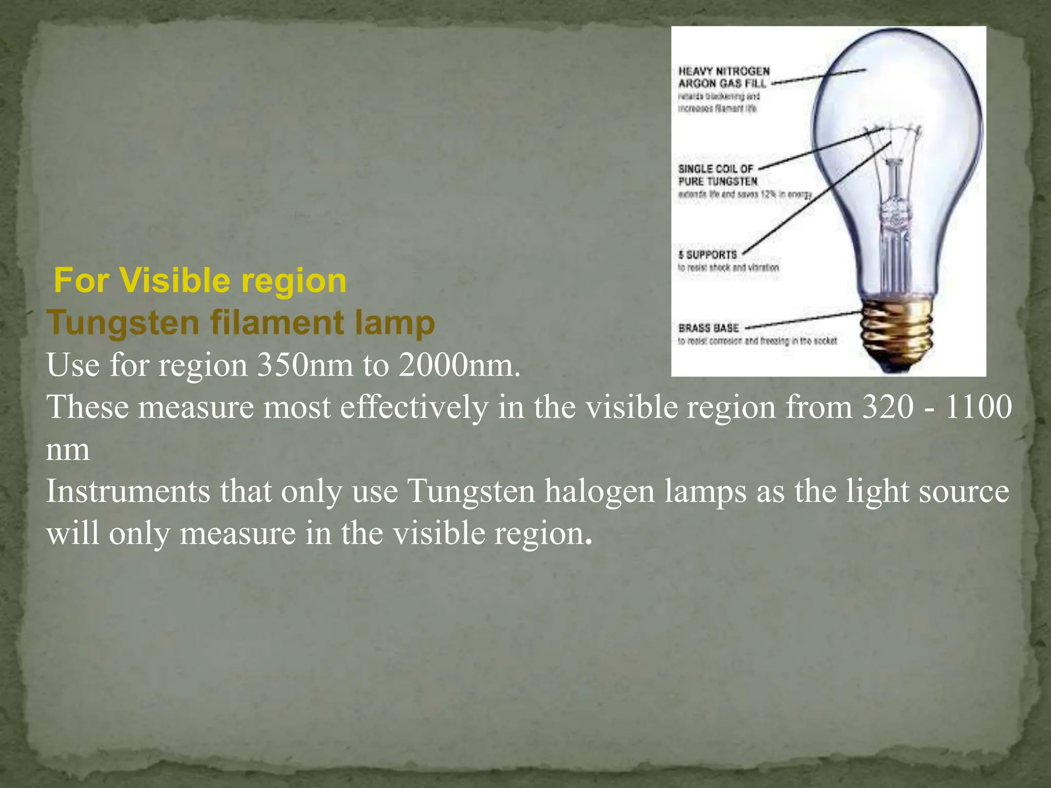
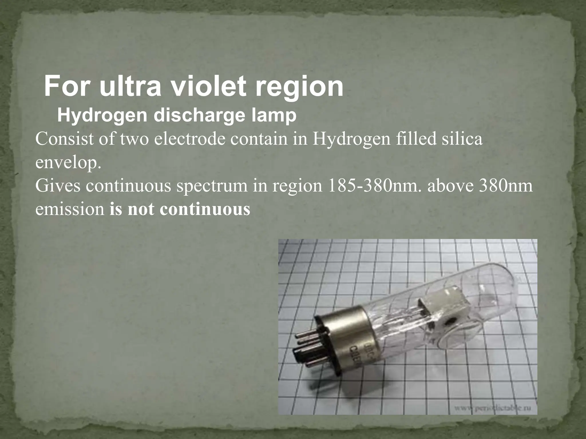
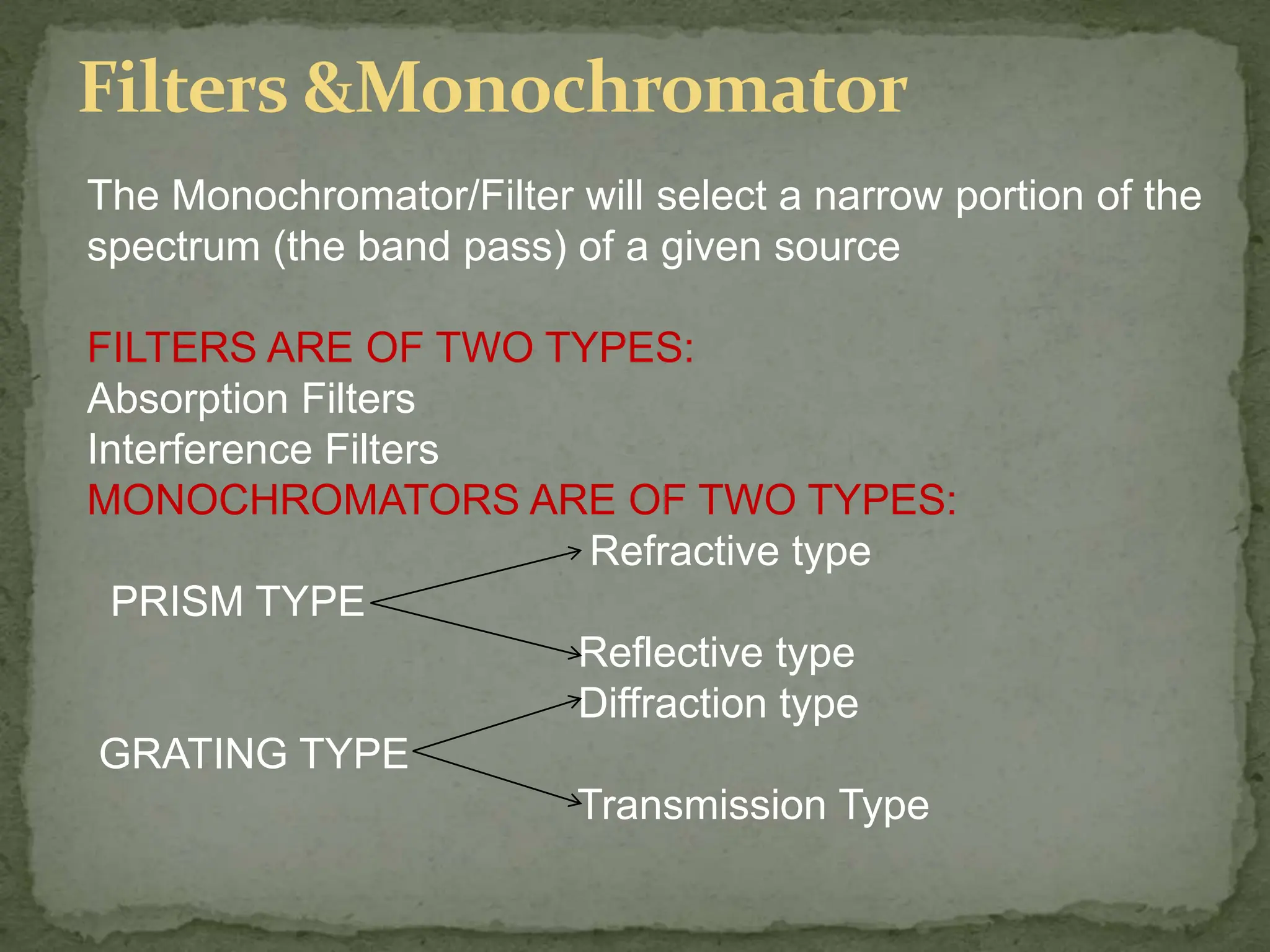
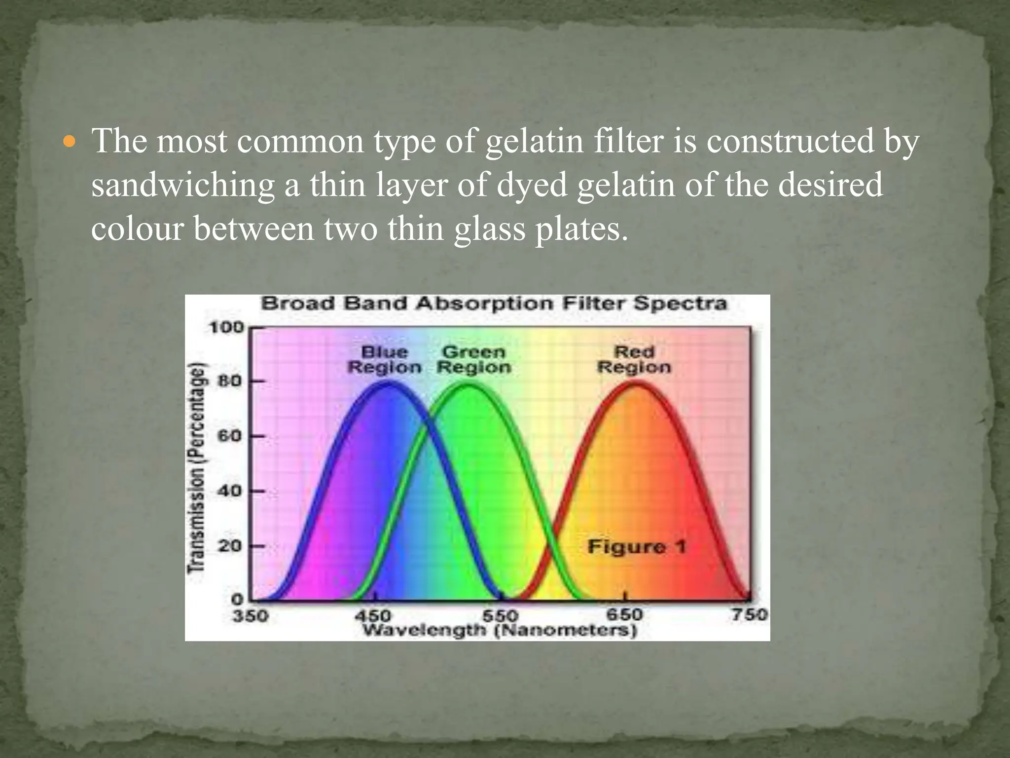
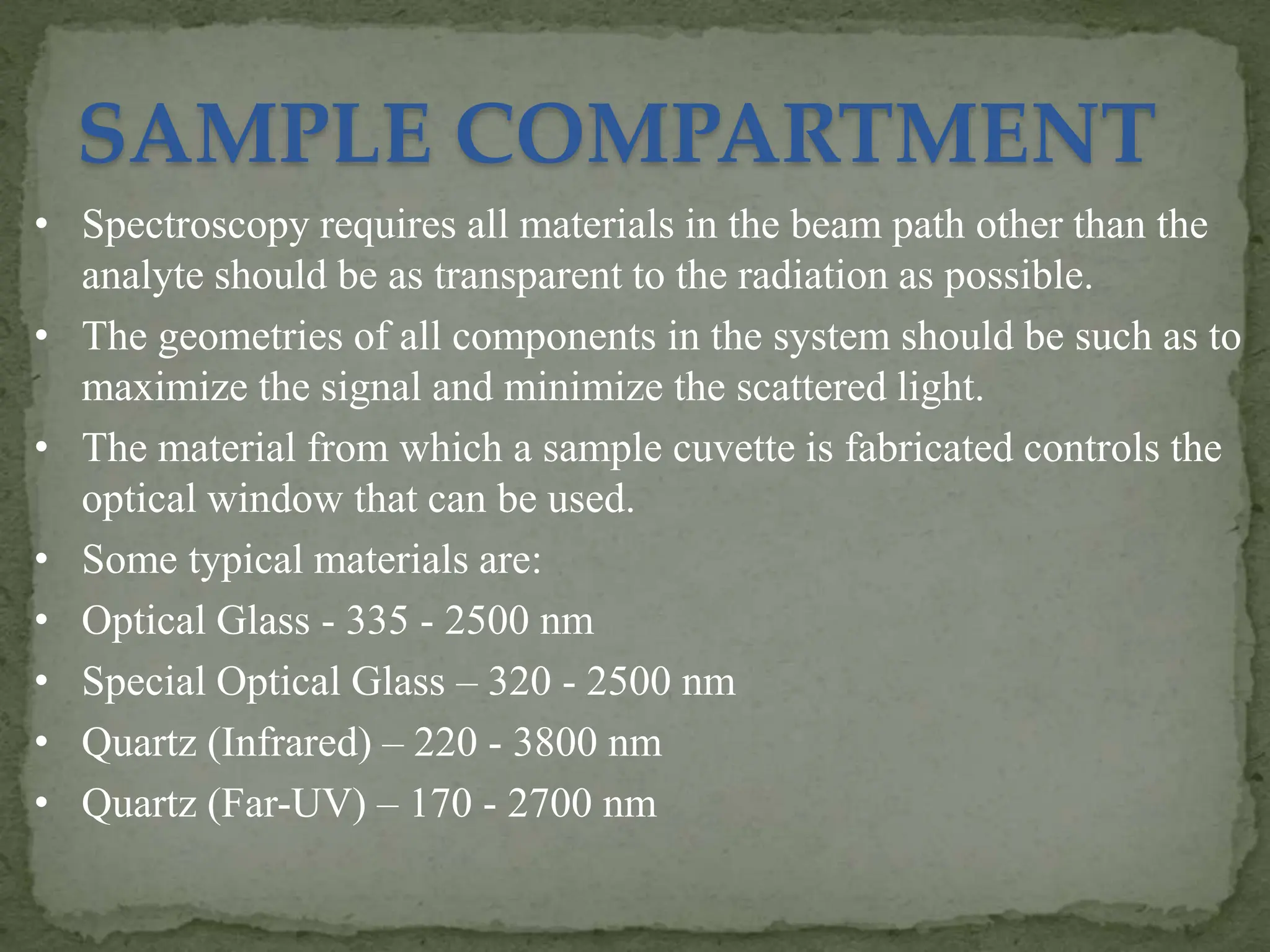
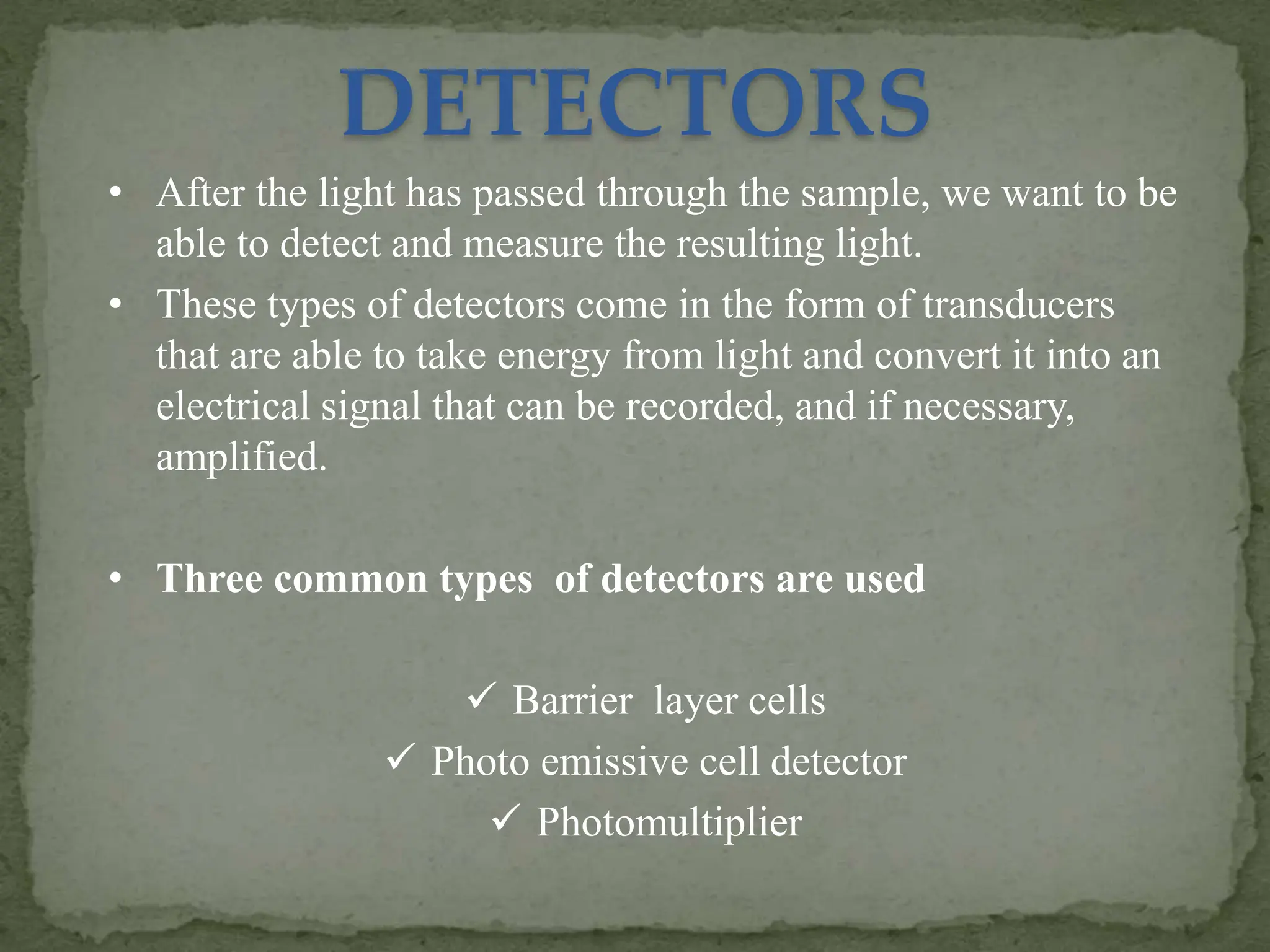
The radiations which travels with speed are called Electro
magnetic radiations.
It vibrates perpendicular to the direction of propagation with a
wave motion.
It is broken in to several regions called as Electro Magnetic
Spectrum
Different regions of the electromagnetic spectrum provide
different kinds of information as a result of interactions.
Light may be considered to have both wave-like and particle-
like characteristics.
Electromagnetic radiation is a propagating
wave in space with electric and magnetic
components
Electromagnetic Spectrum
high frequency (n) low
energy
X-Ray Ultraviolet infrared micro radio
wave wave
ultraviolet visible
wavelength (l)
short long
Ultraviolet region:
Near UV: 200-400 nm
Far or vacuum UV: <200 nm
Visible region:
Violet: 400 - 420 nm
Indigo: 420 - 440 nm
Blue: 440 - 490 nm
Green: 490 - 570 nm
Yellow: 570 - 585 nm
Orange: 585 - 620 nm
Red: 620 - 780 nm
Absorption
When white light passes
through or is reflected by
a colored substance, a
characteristic portion of
the mixed wavelengths is
absorbed.
Colours of visible Spectrum
The apparent colour of the substance is always the complement of the
colour absorbed
Complementary
colour
Colour of
absorbed light
Approximate
wavelength, nm
Green–Yellow
Violet
400-435
Yellow
Blue
435-500
Red
Green
500-570
Blue
Yellow
570-600
Green blue
Orange
600-630
Green
Red
630-700
Spectroscopy – Radiation Terminology
Wavelength (λ) is defined as the distance between
any two consecutive parts of the wave whose
vibrations are in phase, i.e. the distance between
two successive crest or
troughs.
Units: A°, nm , µm
Wave number – the number of
waves in a unit of
length or per cm,-the reciprocal of the
Wavelength.
Units:cm¯¹
Frequency (ν) – is the number of waves passing a
point in one second, i.e. the number of cycles per
second.
Units: (Hz) or s¯¹
Velocity (c): The product obtained from
multiplication of wavelength(λ) and frequency (ν) is
the velocity of light
c=ν x λ
Velocity of light in vacuum is 3x 10¹°cm/s or 3.x10⁸m/s
Photon (quanta) – quantum mechanics nature of
light to explain photoelectric effect
Spectroscopy- Quantification Terms
a) Radiant power (P) – It is the rate at which energy is
transported in a beam of radiant energy
b)Transmittance (T) –It is the ratio of the radiant
power transmitted by the sample (p) to the radiant
power incident on the sample(p₀).Thus transmittance
T = P/P0
c) Absorbance (A) –is the reciprocal of transmittance
A = log(1/T) = - logT = log P0/P
d) Absorptivity (a) –It is the ratio of the absorbance to
the product of concentration and length of optical
path.
It is a constant characteristic of (a=A/bxc) substance
and wavelength
Term and Symbol Definition Alternative Name
and Symbol
Radiant power p, p₀ Energy of radiation Radiation intensity
I,I₀
Absorbance A Log p₀/p Optical density D
Transmittance T p/p₀ Transmission T
Path length of
radiation b
− l ,d
Absorptivity a A/bc Extinction
coefficient k
Molar absorptivity ∈ A/bc Molar extinction
coefficient
The amount of radiation
absorbed may be measured
in a number of ways:
Transmittance, T = I / Io
% Transmittance, T % = 100 T
Absorbance, A = 2 - log₁₀T %
Io: is the intensity of light striking
the sample.
It: is the intensity of transmitted
light.
The relationship between absorbance and
transmittance is illustrated in the following diagram:
So, if all the light passes through a solution without any
absorption, then absorbance is zero, and percent
transmittance is 100%.
If all the light is absorbed, then percent transmittance is
zero, and absorption is infinite.
∈ can also be expressed as follows:
∈ = E( 1 per cent, 1 cm)x molecular weight/10
Where E( 1 per cent, 1 cm) means the absorbance of
1% w/v solution , using a path length of 1cm
Beer's law is applicable to a solution containing
more than one kind of absorbing substance ,
provided there is no interaction among the
various species. For multi component system
A тọтal = A₁+A₂++A₃+A₄‒ ‒ ‒ ‒An
According to Beer-Lambert law: log ( Io / It) = A = e c l
Where Io and It are the incident and transmitted intensities,
A = absorbance and e, a constant= absorptivity (formerly called the extinction coefficient).
The absorptivity depends on the wavelength of light as well as on the identity of the
absorbing substance and the identity of the solvent.
If the concentration is measured in mol.L-1, the absorptivity is called the molar
absorptivity. If several species in a solution absorb at the same wavelength without
chemically interacting with each other, then the total absorbance is the sum of the
individual absorbances for each species.
That is at a particular wavelength: A (total) = e1c1l +e2c2l +e3c3l+ . . . Where ei is the
molar absorptivity of the i-th species with concentration ci at a given wavelength.
For a two component system (say species present are: X & Y) when each component
absorbs appreciably at lambda max of one another, one can write: Al1 = (eX)l1.cX.l
+(eY)l1.cY.l Al2 = (eX)l2.cX.l +(eY)l2.cY.l
Where l1 and l2 are two different wavelengths and cX and cY are concentrations of two
species. In the above equations, A values are measureable. E values for two components at
two lambda max values can be determined from measurements done on single components.
One can measure the absorbance of solutions containing only one of the components at
each of the two lambda max values of the two components, and for each component can
calculate the e values at each of the two wavelengths. Then one needs to measure A of the
mixture at each of the two wavelengths and solve the above two equations for cX and cY.
Thus calibration and measurements at two wavelengths enables two components tobe
determined simultaneously.
Spectrometers
Source
Filters & Monochromator
Sample compartment
Detector
Recorder
Various UV radiation sources are as follows
a. Deuterium lamp
b. Hydrogen lamp
c. Tungsten lamp
d. Xenon discharge lamp
e. Mercury arc lamp
Various Visible radiation sources are as follow
a. Tungsten lamp
b. Mercury vapour lamp
c. Carbonone lamp
For Visible region
Tungsten filament lamp
Use for region 350nm to 2000nm.
These measure most effectively in the visible region from 320 - 1100
nm
Instruments that only use Tungsten halogen lamps as the light source
will only measure in the visible region.
For ultra violet region
Hydrogen discharge lamp
Consist of two electrode contain in Hydrogen filled silica
envelop.
Gives continuous spectrum in region 185-380nm. above 380nm
emission is not continuous
Deuterium lamps:
Deuterium arc lamps measure in the UV region 190 - 370 nm
As Deuterium lamps operate at high temperatures, normal glass
housings cannot be used for the casing. Instead, a fused quartz, UV
glass, or magnesium fluoride envelope is used.
When run continuously typical lamp life for a Deuterium lamp is
approximately 1000 hours, however this can be extended by up to a
factor of three using PTR technology.
Deuterium lamps are always used with a Tungsten halogen lamp to
allow measurements to be performed in both the UV and visible
regions.
The Monochromator/Filter will select a narrow portion of the
spectrum (the band pass) of a given source
FILTERS ARE OF TWO TYPES:
Absorption Filters
Interference Filters
MONOCHROMATORS ARE OF TWO TYPES:
Refractive type
PRISM TYPE
Reflective type
Diffraction type
GRATING TYPE
Transmission Type
ABSORPTION FILTERS
Absorption filters, commonly manufactured from dyed
glass or pigmented gelatin resins
Band widths are extremely large {300 – 250 nm}
Combining two absorbance filters of different λmax
 The most common type of gelatin filter is constructed by
sandwiching a thin layer of dyed gelatin of the desired
colour between two thin glass plates.
These are used to select
wavelengths more accurately by
providing a narrow band pass
typically of around 10nm
These filters rely on optical
interference (destructive wave
addition) to provide narrow bands
of radiation.
• Interference filter consists of a dielectric spacer film made up of CaF2, MgF2
between two parallel reflecting films.
• As light passes from one medium to the other the direction and wavelength of
light can be changed based on the index of refraction of both mediums involved
and the angle of the incident and exiting light (For more look at Snell’s law).
• Due to this behaviour, constructive and destructive interference can be
controlled by varying the thickness (d) of a transparent dielectric material
between two semi-reflective sheets and the angle the light is shined upon the
surface.
• As light hits the first semi-reflective sheet, a portion is reflected, while the rest
travels through the dielectric to be bent and reflected by the second semi-
reflective sheet.
• If the conditions are correct, the reflected light and the initial incident light will
be in phase and constructive interference occurs for only a particular
wavelength
It consists of entrance slit, collimator lens, Prism, Focusing
lens, Exit slit.
Reflective type prism Monochromator or Littrow type
mounting :
• Gratings are rulings made on
glass, Quartz or alkyl halides
• Depending upon the
instrument no. of rulings per
mm defers
• If it is UV-Visible no. of
gratings per mm are more
than 3600.
• The mechanism is that diffraction produces
reinforcement.
• The rays which are incident on the grating gets
reinforced with the reflected rays and hence
resulting radiation has wavelength governed by
equation
m λ =b(sin I + sin r)
m – order
λ – desired wavelength
b – grating spacing
i – angle of incidence
r - angle of diffraction
TRANSMISSION TYPE GRATING:
It is similar to diffraction grating, but refraction produces
instead of reflection
Refraction produces reinforcement
The wavelength of radiation produced by transmission grating
can be expressed by
d sin Φ
λ = -------------- d = 1/lines per cm
m
SAMPLE COMPARTMENT
• Spectroscopy requires all materials in the beam path other than the
analyte should be as transparent to the radiation as possible.
• The geometries of all components in the system should be such as to
maximize the signal and minimize the scattered light.
• The material from which a sample cuvette is fabricated controls the
optical window that can be used.
• Some typical materials are:
• Optical Glass - 335 - 2500 nm
• Special Optical Glass – 320 - 2500 nm
• Quartz (Infrared) – 220 - 3800 nm
• Quartz (Far-UV) – 170 - 2700 nm
• After the light has passed through the sample, we want to be
able to detect and measure the resulting light.
• These types of detectors come in the form of transducers
that are able to take energy from light and convert it into an
electrical signal that can be recorded, and if necessary,
amplified.
• Three common types of detectors are used
 Barrier layer cells
 Photo emissive cell detector
 Photomultiplier
DETECTORS
BARRIER LAYER CELL or PHOTO VOLTAIC
CELL
• It consist of
 The steel support plate 'A'
 layer of metallic selenium 'B', which is a few
hundredths of a millimetre in thickness.
 'C' is a thin transparent electrically-conductive layer,
applied by cathodic sputtering.
• It consists of a metallic base plate like iron or aluminium
which acts as one electrode.
• On its surface, a thin layer of a semiconductor metal like
selenium is deposited.
• Then the surface of selenium is covered by a very thin
layer of silver or gold which acts as a second collector
tube.
• When the radiation is incident upon the surface of
selenium, electrons are generated at the selenium- silver
surface and the electrons are collected by the silver.
• This accumulation at the silver surface creates an
electric voltage difference between the silver surface and
the basis of the cell.
Photo emissive cells Detector
• Phototubes are also known as photo emissive cells.
• A phototube consists of an evacuated glass bulb.
• There is light sensitive cathode inside it.
• The inner surface of cathode is coated with light sensitive
layer such as potassium oxide and silver oxide.
• When radiation is incident upon a cathode, photoelectrons
are emitted.
• These are collected by an anode.
• Then these are returned via external circuit. And by this
process current is amplified and recorded.
• The photomultiplier tube is a commonly used detector in UV
spectroscopy.
• It consists of a photo emissive cathode (a cathode which emits
electrons when struck by photons of radiation), several dynodes
(which emit several electrons for each electron striking them)
and an anode.
• A photon of radiation entering the tube strikes the cathode,
causing the emission of several electrons.
• These electrons are accelerated towards the first dynode (which
is 90V more positive than the cathode).
• The electrons strike the first dynode, causing the emission of
several electrons for each incident electron.
• These electrons are then accelerated towards the second
dynode, to produce more electrons which are accelerated
towards dynode three and so on.
• Eventually, the electrons are collected at the anode.
• By this time, each original photon has produced 106 - 107
electrons.
• The resulting current is amplified and measured.
• Photomultipliers are very sensitive to UV and visible
radiation.
• They have fast response times.
• Intense light damages photomultipliers;
• they are limited to measuring low power radiation.
APPLICATIONS:
A. APPLICATIONS IN ORGANIC COMPOUNDS
1.It is helps to show the relationship between different groups, it is useful to
detect the conjugation of the compounds
2.Detection of geometrical isomers, In case of geometrical isomers
compounds, that trans isomers exhibits λmax at slightly longer wavelength
and have larger extinction coefficient then the cis isomers .
3.Detection of functional groups, it is possible to detect the presence of
certain functional groups with the help of UV Spectrum.
GENERAL APPLICATIONS:
1. Qualitative analysis, UV absorption spectroscopy can characterizes
those type of compounds which absorb UV radiation. Identification is
done by comparing the absorption spectrum with the spectra of known
compound.
2. It is useful in Quantitative analysis of the compounds.
3. Detection of impurities, UV absorption spectroscopy is the one of the
best method for detecting impurities in organic compounds.
4. Tautomeric equilibrium, UV spectroscopy can be used to determine the
percentage of various keto and enol forms present in tautomeric equilibrium.
5. Chemical kinetics, UV spectroscopy can be used to study the kinetics of
reactions.
6. Molecular weight determination, molecular weights of compounds can be
measured by spectroscopy.
7. Analysis of inorganic compounds.
8. Measuring concentration of solution, absorption band can also used to
determine the concentration of compounds in a solution.
9. Inorganic chemistry, absorption spectra have been used in connection with
many problems in inorganic chemistry.
10. It is useful to determine the structure of the chloral.
References:
Instrumental methods of chemical analysis
-B.K Sharma
Instrumental methods of chemical analysis
- Gurdeep R. Chatwal
-Sham K. Anand
Principles of Instrumental Analysis
- Skoog
THANK YOU

UV-Visible.ppt

  • 1.
    Light interacting withmatter as an analytical tool
  • 18.
    The radiations whichtravels with speed are called Electro magnetic radiations. It vibrates perpendicular to the direction of propagation with a wave motion. It is broken in to several regions called as Electro Magnetic Spectrum Different regions of the electromagnetic spectrum provide different kinds of information as a result of interactions. Light may be considered to have both wave-like and particle- like characteristics.
  • 19.
    Electromagnetic radiation isa propagating wave in space with electric and magnetic components
  • 20.
    Electromagnetic Spectrum high frequency(n) low energy X-Ray Ultraviolet infrared micro radio wave wave ultraviolet visible wavelength (l) short long
  • 21.
    Ultraviolet region: Near UV:200-400 nm Far or vacuum UV: <200 nm Visible region: Violet: 400 - 420 nm Indigo: 420 - 440 nm Blue: 440 - 490 nm Green: 490 - 570 nm Yellow: 570 - 585 nm Orange: 585 - 620 nm Red: 620 - 780 nm Absorption When white light passes through or is reflected by a colored substance, a characteristic portion of the mixed wavelengths is absorbed.
  • 22.
    Colours of visibleSpectrum The apparent colour of the substance is always the complement of the colour absorbed Complementary colour Colour of absorbed light Approximate wavelength, nm Green–Yellow Violet 400-435 Yellow Blue 435-500 Red Green 500-570 Blue Yellow 570-600 Green blue Orange 600-630 Green Red 630-700
  • 23.
    Spectroscopy – RadiationTerminology Wavelength (λ) is defined as the distance between any two consecutive parts of the wave whose vibrations are in phase, i.e. the distance between two successive crest or troughs. Units: A°, nm , µm Wave number – the number of waves in a unit of length or per cm,-the reciprocal of the Wavelength. Units:cm¯¹
  • 24.
    Frequency (ν) –is the number of waves passing a point in one second, i.e. the number of cycles per second. Units: (Hz) or s¯¹ Velocity (c): The product obtained from multiplication of wavelength(λ) and frequency (ν) is the velocity of light c=ν x λ Velocity of light in vacuum is 3x 10¹°cm/s or 3.x10⁸m/s Photon (quanta) – quantum mechanics nature of light to explain photoelectric effect
  • 25.
    Spectroscopy- Quantification Terms a)Radiant power (P) – It is the rate at which energy is transported in a beam of radiant energy b)Transmittance (T) –It is the ratio of the radiant power transmitted by the sample (p) to the radiant power incident on the sample(p₀).Thus transmittance T = P/P0 c) Absorbance (A) –is the reciprocal of transmittance A = log(1/T) = - logT = log P0/P d) Absorptivity (a) –It is the ratio of the absorbance to the product of concentration and length of optical path. It is a constant characteristic of (a=A/bxc) substance and wavelength
  • 26.
    Term and SymbolDefinition Alternative Name and Symbol Radiant power p, p₀ Energy of radiation Radiation intensity I,I₀ Absorbance A Log p₀/p Optical density D Transmittance T p/p₀ Transmission T Path length of radiation b − l ,d Absorptivity a A/bc Extinction coefficient k Molar absorptivity ∈ A/bc Molar extinction coefficient
  • 27.
    The amount ofradiation absorbed may be measured in a number of ways: Transmittance, T = I / Io % Transmittance, T % = 100 T Absorbance, A = 2 - log₁₀T % Io: is the intensity of light striking the sample. It: is the intensity of transmitted light.
  • 28.
    The relationship betweenabsorbance and transmittance is illustrated in the following diagram: So, if all the light passes through a solution without any absorption, then absorbance is zero, and percent transmittance is 100%. If all the light is absorbed, then percent transmittance is zero, and absorption is infinite.
  • 32.
    ∈ can alsobe expressed as follows: ∈ = E( 1 per cent, 1 cm)x molecular weight/10 Where E( 1 per cent, 1 cm) means the absorbance of 1% w/v solution , using a path length of 1cm
  • 33.
    Beer's law isapplicable to a solution containing more than one kind of absorbing substance , provided there is no interaction among the various species. For multi component system A тọтal = A₁+A₂++A₃+A₄‒ ‒ ‒ ‒An
  • 37.
    According to Beer-Lambertlaw: log ( Io / It) = A = e c l Where Io and It are the incident and transmitted intensities, A = absorbance and e, a constant= absorptivity (formerly called the extinction coefficient). The absorptivity depends on the wavelength of light as well as on the identity of the absorbing substance and the identity of the solvent. If the concentration is measured in mol.L-1, the absorptivity is called the molar absorptivity. If several species in a solution absorb at the same wavelength without chemically interacting with each other, then the total absorbance is the sum of the individual absorbances for each species. That is at a particular wavelength: A (total) = e1c1l +e2c2l +e3c3l+ . . . Where ei is the molar absorptivity of the i-th species with concentration ci at a given wavelength. For a two component system (say species present are: X & Y) when each component absorbs appreciably at lambda max of one another, one can write: Al1 = (eX)l1.cX.l +(eY)l1.cY.l Al2 = (eX)l2.cX.l +(eY)l2.cY.l Where l1 and l2 are two different wavelengths and cX and cY are concentrations of two species. In the above equations, A values are measureable. E values for two components at two lambda max values can be determined from measurements done on single components. One can measure the absorbance of solutions containing only one of the components at each of the two lambda max values of the two components, and for each component can calculate the e values at each of the two wavelengths. Then one needs to measure A of the mixture at each of the two wavelengths and solve the above two equations for cX and cY. Thus calibration and measurements at two wavelengths enables two components tobe determined simultaneously.
  • 53.
  • 54.
    Source Filters & Monochromator Samplecompartment Detector Recorder
  • 57.
    Various UV radiationsources are as follows a. Deuterium lamp b. Hydrogen lamp c. Tungsten lamp d. Xenon discharge lamp e. Mercury arc lamp Various Visible radiation sources are as follow a. Tungsten lamp b. Mercury vapour lamp c. Carbonone lamp
  • 58.
    For Visible region Tungstenfilament lamp Use for region 350nm to 2000nm. These measure most effectively in the visible region from 320 - 1100 nm Instruments that only use Tungsten halogen lamps as the light source will only measure in the visible region.
  • 59.
    For ultra violetregion Hydrogen discharge lamp Consist of two electrode contain in Hydrogen filled silica envelop. Gives continuous spectrum in region 185-380nm. above 380nm emission is not continuous
  • 60.
    Deuterium lamps: Deuterium arclamps measure in the UV region 190 - 370 nm As Deuterium lamps operate at high temperatures, normal glass housings cannot be used for the casing. Instead, a fused quartz, UV glass, or magnesium fluoride envelope is used. When run continuously typical lamp life for a Deuterium lamp is approximately 1000 hours, however this can be extended by up to a factor of three using PTR technology. Deuterium lamps are always used with a Tungsten halogen lamp to allow measurements to be performed in both the UV and visible regions.
  • 61.
    The Monochromator/Filter willselect a narrow portion of the spectrum (the band pass) of a given source FILTERS ARE OF TWO TYPES: Absorption Filters Interference Filters MONOCHROMATORS ARE OF TWO TYPES: Refractive type PRISM TYPE Reflective type Diffraction type GRATING TYPE Transmission Type
  • 62.
    ABSORPTION FILTERS Absorption filters,commonly manufactured from dyed glass or pigmented gelatin resins Band widths are extremely large {300 – 250 nm} Combining two absorbance filters of different λmax
  • 63.
     The mostcommon type of gelatin filter is constructed by sandwiching a thin layer of dyed gelatin of the desired colour between two thin glass plates.
  • 65.
    These are usedto select wavelengths more accurately by providing a narrow band pass typically of around 10nm These filters rely on optical interference (destructive wave addition) to provide narrow bands of radiation.
  • 67.
    • Interference filterconsists of a dielectric spacer film made up of CaF2, MgF2 between two parallel reflecting films. • As light passes from one medium to the other the direction and wavelength of light can be changed based on the index of refraction of both mediums involved and the angle of the incident and exiting light (For more look at Snell’s law). • Due to this behaviour, constructive and destructive interference can be controlled by varying the thickness (d) of a transparent dielectric material between two semi-reflective sheets and the angle the light is shined upon the surface. • As light hits the first semi-reflective sheet, a portion is reflected, while the rest travels through the dielectric to be bent and reflected by the second semi- reflective sheet. • If the conditions are correct, the reflected light and the initial incident light will be in phase and constructive interference occurs for only a particular wavelength
  • 69.
    It consists ofentrance slit, collimator lens, Prism, Focusing lens, Exit slit.
  • 70.
    Reflective type prismMonochromator or Littrow type mounting :
  • 71.
    • Gratings arerulings made on glass, Quartz or alkyl halides • Depending upon the instrument no. of rulings per mm defers • If it is UV-Visible no. of gratings per mm are more than 3600.
  • 74.
    • The mechanismis that diffraction produces reinforcement. • The rays which are incident on the grating gets reinforced with the reflected rays and hence resulting radiation has wavelength governed by equation m λ =b(sin I + sin r) m – order λ – desired wavelength b – grating spacing i – angle of incidence r - angle of diffraction
  • 75.
    TRANSMISSION TYPE GRATING: Itis similar to diffraction grating, but refraction produces instead of reflection Refraction produces reinforcement The wavelength of radiation produced by transmission grating can be expressed by d sin Φ λ = -------------- d = 1/lines per cm m
  • 76.
    SAMPLE COMPARTMENT • Spectroscopyrequires all materials in the beam path other than the analyte should be as transparent to the radiation as possible. • The geometries of all components in the system should be such as to maximize the signal and minimize the scattered light. • The material from which a sample cuvette is fabricated controls the optical window that can be used. • Some typical materials are: • Optical Glass - 335 - 2500 nm • Special Optical Glass – 320 - 2500 nm • Quartz (Infrared) – 220 - 3800 nm • Quartz (Far-UV) – 170 - 2700 nm
  • 77.
    • After thelight has passed through the sample, we want to be able to detect and measure the resulting light. • These types of detectors come in the form of transducers that are able to take energy from light and convert it into an electrical signal that can be recorded, and if necessary, amplified. • Three common types of detectors are used  Barrier layer cells  Photo emissive cell detector  Photomultiplier DETECTORS
  • 78.
    BARRIER LAYER CELLor PHOTO VOLTAIC CELL • It consist of  The steel support plate 'A'  layer of metallic selenium 'B', which is a few hundredths of a millimetre in thickness.  'C' is a thin transparent electrically-conductive layer, applied by cathodic sputtering.
  • 80.
    • It consistsof a metallic base plate like iron or aluminium which acts as one electrode. • On its surface, a thin layer of a semiconductor metal like selenium is deposited. • Then the surface of selenium is covered by a very thin layer of silver or gold which acts as a second collector tube. • When the radiation is incident upon the surface of selenium, electrons are generated at the selenium- silver surface and the electrons are collected by the silver. • This accumulation at the silver surface creates an electric voltage difference between the silver surface and the basis of the cell.
  • 81.
    Photo emissive cellsDetector • Phototubes are also known as photo emissive cells. • A phototube consists of an evacuated glass bulb. • There is light sensitive cathode inside it. • The inner surface of cathode is coated with light sensitive layer such as potassium oxide and silver oxide. • When radiation is incident upon a cathode, photoelectrons are emitted. • These are collected by an anode. • Then these are returned via external circuit. And by this process current is amplified and recorded.
  • 83.
    • The photomultipliertube is a commonly used detector in UV spectroscopy. • It consists of a photo emissive cathode (a cathode which emits electrons when struck by photons of radiation), several dynodes (which emit several electrons for each electron striking them) and an anode. • A photon of radiation entering the tube strikes the cathode, causing the emission of several electrons. • These electrons are accelerated towards the first dynode (which is 90V more positive than the cathode). • The electrons strike the first dynode, causing the emission of several electrons for each incident electron.
  • 84.
    • These electronsare then accelerated towards the second dynode, to produce more electrons which are accelerated towards dynode three and so on. • Eventually, the electrons are collected at the anode. • By this time, each original photon has produced 106 - 107 electrons. • The resulting current is amplified and measured. • Photomultipliers are very sensitive to UV and visible radiation. • They have fast response times. • Intense light damages photomultipliers; • they are limited to measuring low power radiation.
  • 86.
    APPLICATIONS: A. APPLICATIONS INORGANIC COMPOUNDS 1.It is helps to show the relationship between different groups, it is useful to detect the conjugation of the compounds 2.Detection of geometrical isomers, In case of geometrical isomers compounds, that trans isomers exhibits λmax at slightly longer wavelength and have larger extinction coefficient then the cis isomers . 3.Detection of functional groups, it is possible to detect the presence of certain functional groups with the help of UV Spectrum. GENERAL APPLICATIONS: 1. Qualitative analysis, UV absorption spectroscopy can characterizes those type of compounds which absorb UV radiation. Identification is done by comparing the absorption spectrum with the spectra of known compound. 2. It is useful in Quantitative analysis of the compounds. 3. Detection of impurities, UV absorption spectroscopy is the one of the best method for detecting impurities in organic compounds.
  • 87.
    4. Tautomeric equilibrium,UV spectroscopy can be used to determine the percentage of various keto and enol forms present in tautomeric equilibrium. 5. Chemical kinetics, UV spectroscopy can be used to study the kinetics of reactions. 6. Molecular weight determination, molecular weights of compounds can be measured by spectroscopy. 7. Analysis of inorganic compounds. 8. Measuring concentration of solution, absorption band can also used to determine the concentration of compounds in a solution. 9. Inorganic chemistry, absorption spectra have been used in connection with many problems in inorganic chemistry. 10. It is useful to determine the structure of the chloral.
  • 88.
    References: Instrumental methods ofchemical analysis -B.K Sharma Instrumental methods of chemical analysis - Gurdeep R. Chatwal -Sham K. Anand Principles of Instrumental Analysis - Skoog
  • 89.