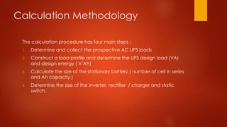
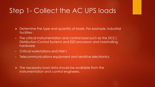
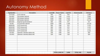
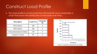
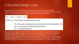
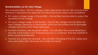
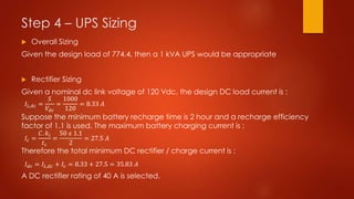
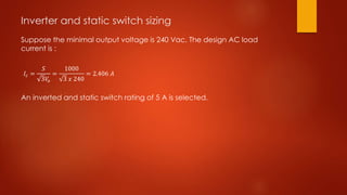
UPS
 UPS ( Uninterruptible power supply )
 Used to support critical/sensitive load
 It is typically a battery-backed system which will continue to
operate for a specified amount of time after main power supply
interruption.
 Used as stable power supplies that provide a reasonably constant
voltage and frequency output, independent of voltage input.
 Particularly useful for sensitive electrical equipment on main power
supplies that are prone to voltage or frequency fluctuations or
instability.
Why do the calculation ?
 UPS sizing calculation will determine the ratings of the main UPS
system component :
- Rectifier
- battery bank
- Inverter
In addition, the calculation result will also help determine the indicative
dimensions of the equipment (e.g. size of battery banks )for preliminary
layout purposes.
When to do calculation ?
The UPS sizing calculation can be done when the following prerequisite
information is known :
- UPS load that need to be supported
- Input / output AC voltage
- Autonomy time
- Battery type
Calculation Methodology
The calculation procedure has four main steps :
1. Determine and collect the prospective AC UPS loads
2. Construct a load profile and determine the UPS design load (VA)
and design energy ( V Ah)
3. Calculate the size of the stationary battery ( number of cell in series
and Ah capacity )
4. Determine the size of the inverter, rectifier / charger and static
switch.
Step 1- Collect the AC UPS loads
 Determine the type and quantity of loads. For example, industrial
facilities :
 The critical instrumentation and control load such as the DCS (
Distribution Control System) and ESD processor and marshalling
hardware
 Critical workstations and HMI’s
 Telecommunications equipment and sensitive electronics
 The necessary load data should be available from the
instrumentation and control engineers.
Step 2- Load Profile, Design Load,
and Design Energy
 Refer to the load profile calculation for detail on how to construct a
load profile, calculate design load and design energy.
 The “Autonomy method” for constructing load profile is typically
used for AC UPS system. Autonomy method is the number of hours
that the load needs to be supported during a power supply
interruption
 The autonomy time is often specified by the client ( in their
standards )
 IEEE 446 “IEEE Recommended Practice for Emergency and Standby
Power System for Industrial and Commercial Application” has some
guidance for autonomy time. Sometimes a single autonomy time is
used for entire UPS load, which obviously makes the construction of
the load profile easier to compute.
Calculating the Consumed Load VA
 For each load in VA, this can be calculated as follows:
Autonomy Method
Construct Load Profile
 The load profile is constructed from the load list and is essentially a
chart that shows the distribution of the loads over time.
Calculate Design Load
The design load is the instantaneous load for which the power conversion,
distribution and protection devices should be rated, e.g. rectifiers, inverters, cables,
fuses, circuit breakers, etc. The design can be calculated as follows:
It is common to make considerations for future load growth (typically somewhere
between 5 and 20%), to allow future loads to be supported. If no future loads are
expected, then this contingency can be ignored. A design margin is used to
account for any potential inaccuracies in estimating the loads, less-than-optimum
operating conditions due to improper maintenance, etc. Typically, a design margin
of 10% to 15% is recommended, but this may also depend on Client preferences.
Design Energy Demand
 The design energy demand is used for sizing energy storage
devices. From the load profile, the total energy (in terms of VAh)
can be computed by finding the area underneath the load profile
curve (i.e. integrating instantaneous power with respect to time over
the autonomy or 24h period). The design energy demand (or design
VAh) can then be calculated by the following equation:
Step 3 – Battery Sizing
Selection of type battery should consider the following factor as suggested by IEEE :
 Physical characteristics, e.g. dimensions, weight, container material, intercell connections, terminals
 application design life and expected life of cell
 Frequency and depth of discharge
 Ambient temperature
 Charging characteristics
 Maintenance requirements
 Ventilation requirements
 Cell orientation requirements (sealed lead-acid and NiCd)
 Seismic factors (shock and vibration)
Next, find the characteristics of the battery cells, typically from supplier data sheets. The characteristics
that should be collected include:
 Battery cell capacities (Ah)
 Cell temperature
 Electrolyte density at full charge (for lead-acid batteries)
 Cell float voltage
 Cell end-of-discharge voltage (EODV).
Nominal Battery (or DC Link) Voltage
The nominal battery / DC link voltage is often selected by the AC UPS manufacturer.
However, if required to be selected, the following factors need to be considered:
 DC output voltage range of the rectifier – the rectifier must be able to output the
specified DC link voltage
 DC input voltage range of the inverter – the DC link voltage must be within the
input voltage tolerances of the inverter. Note that the battery end of discharge
voltage should be within these tolerances.
 Number of battery cells required in series – this will affect the overall dimensions
and size of the battery rack. If physical space is a constraint, then less batteries in
series would be preferable.
 Total DC link current (at full load) – this will affect the sizing of the DC cables and
inter-cell battery links. Obviously the smaller the better.
Number of Cells in Series
The number of battery cells required to be connected in series must be
between the two following limits :
The limits are based on the input voltage tolerance of the inverter. As a
maximum, the battery at float voltage (or boost if applicable) needs to
be within the maximum input voltage range of the inverter. Likewise as
a minimum, the battery at its end of discharge voltage must be within
the minimum input voltage range of the inverter.
Determine Battery Capacity
The minimum battery capacity required to accommodate the design
load over the specified autonomy time can be calculated as follows :
Step 4 – UPS Sizing
Overall ups sizing
Most of the time, all you need to provide is the overall UPS kVA rating
and the UPS vendor will do the rest. Given the design load calculated
in Step 2, select an overall UPS rating that exceeds the design load.
Vendors typically have standard UPS ratings, so it is possible to simply
select the first standard rating that exceeds the design load. For
example, if the design load 12kVA, then the next size unit (e.g. 15kVA
UPS) would be selected.
Rectifier / Charger Sizing
The rectifier / charger should be sized to supply the inverter at full load
and also charge the batteries (at the maximum charge current). The
design DC load current can be calculated by :
Inverter Sizing
The inverter must be rated to continuously supply the UPS loads. Therefore,
the inverter can be sized using the design AC load current (based on the
selected UPS kVA rating) :
Static Switch Sizing
Like the inverter, the static switch must be rated to continuously supply the
UPS loads. Therefore, the static switch can be sized using the design AC
load current (as above for the inverter sizing)
Example case :
𝑆𝑑=𝑆𝑝(1+𝑘𝑔)(1+𝑘𝑐)
𝑆𝑝=150 + 200 + 200 + 90 = 640 𝑉𝐴
=640(1+0.1)(1+0.1)= 774.4 VA
𝐸𝑑=𝐸𝑡(1+𝑘𝑔)(1+𝑘𝑐)
𝐸𝑡=150.6 + 200.4 + 200.4 + 90.2 = 2680 𝑉𝐴h
=2680(1+0.1)(1+0.1)= 3242.8 V Ah
Step 1 & 2 :
Peak Load :
Design Load :
Energy demand :
Design Energy demand :
Step 3 – Battery Sizing
Suppose that the nominal battery voltage is Vdc = 120Vdc, the cell charging
voltage is Vc = 2.25Vdc/cell, the end-of-discharge voltage is Veod = 1.8Vdc/cell,
and the minimum and maximum load voltage tolerances areVl,min = 10%
and Vl,max = 20% respectively.
Given a depth of discharge kdod = 80%, battery ageing factor ka = 25%,
temperature correction factor for vented cells at 30 deg C of kt = 0.956 and a
capacity rating factor of kc = 10%, the minimum battery capacity is:
𝑁𝑚𝑎𝑥 =
𝑉𝑑𝑐(1 + 𝑉𝑖,𝑚𝑎𝑥)
𝑉𝑓
=
120(1 + 0.2)
2.25
= 64 𝑐𝑒𝑙𝑙
𝑁𝑚𝑖𝑛 =
𝑉𝑑𝑐(1 + 𝑉𝑖,𝑚𝑎𝑥)
𝑉𝑒𝑜𝑑
=
120(1 − 0.1)
1.8
= 60 𝑐𝑒𝑙𝑙
𝐶𝑚𝑖𝑛 =
𝐸𝑑(𝑘𝑎𝑥 𝑘𝑡𝑥𝑘𝑐)
𝑉𝑑𝑐 𝑥 𝑘𝑑𝑜𝑑
=
3242.8(1.25 𝑥 1.1 𝑥 0.956)
120 𝑥 0.8
= 44.4 𝐴ℎ
Step 4 – UPS Sizing
 Overall Sizing
Given the design load of 774.4, then a 1 kVA UPS would be appropriate
 Rectifier Sizing
Given a nominal dc link voltage of 120 Vdc, the design DC load current is :
Suppose the minimum battery recharge time is 2 hour and a recharge efficiency
factor of 1.1 is used. The maximum battery charging current is :
Therefore the total minimum DC rectifier / charge current is :
A DC rectifier rating of 40 A is selected.
𝐼𝐿,𝑑𝑐 =
𝑆
𝑉𝑑𝑐
=
1000
120
= 8.33 𝐴
𝐼𝑐 =
𝐶. 𝑘𝑖
𝑡𝑐
=
50 𝑥 1.1
2
= 27.5 𝐴
𝐼𝑑𝑐 = 𝐼𝐿,𝑑𝑐 + 𝐼𝑐 = 8.33 + 27.5 = 35.83 𝐴
Inverter and static switch sizing
Suppose the minimal output voltage is 240 Vac. The design AC load
current is :
An inverted and static switch rating of 5 A is selected.
𝐼𝑐 =
𝑆
3𝑉
𝑜
=
1000
3 𝑥 240
= 2.406 𝐴

UPS_Sizing_Calculation__170450556677.pdf

  • 1.
    UPS  UPS (Uninterruptible power supply )  Used to support critical/sensitive load  It is typically a battery-backed system which will continue to operate for a specified amount of time after main power supply interruption.  Used as stable power supplies that provide a reasonably constant voltage and frequency output, independent of voltage input.  Particularly useful for sensitive electrical equipment on main power supplies that are prone to voltage or frequency fluctuations or instability.
  • 2.
    Why do thecalculation ?  UPS sizing calculation will determine the ratings of the main UPS system component : - Rectifier - battery bank - Inverter In addition, the calculation result will also help determine the indicative dimensions of the equipment (e.g. size of battery banks )for preliminary layout purposes.
  • 3.
    When to docalculation ? The UPS sizing calculation can be done when the following prerequisite information is known : - UPS load that need to be supported - Input / output AC voltage - Autonomy time - Battery type
  • 4.
    Calculation Methodology The calculationprocedure has four main steps : 1. Determine and collect the prospective AC UPS loads 2. Construct a load profile and determine the UPS design load (VA) and design energy ( V Ah) 3. Calculate the size of the stationary battery ( number of cell in series and Ah capacity ) 4. Determine the size of the inverter, rectifier / charger and static switch.
  • 5.
    Step 1- Collectthe AC UPS loads  Determine the type and quantity of loads. For example, industrial facilities :  The critical instrumentation and control load such as the DCS ( Distribution Control System) and ESD processor and marshalling hardware  Critical workstations and HMI’s  Telecommunications equipment and sensitive electronics  The necessary load data should be available from the instrumentation and control engineers.
  • 6.
    Step 2- LoadProfile, Design Load, and Design Energy  Refer to the load profile calculation for detail on how to construct a load profile, calculate design load and design energy.  The “Autonomy method” for constructing load profile is typically used for AC UPS system. Autonomy method is the number of hours that the load needs to be supported during a power supply interruption  The autonomy time is often specified by the client ( in their standards )  IEEE 446 “IEEE Recommended Practice for Emergency and Standby Power System for Industrial and Commercial Application” has some guidance for autonomy time. Sometimes a single autonomy time is used for entire UPS load, which obviously makes the construction of the load profile easier to compute.
  • 7.
    Calculating the ConsumedLoad VA  For each load in VA, this can be calculated as follows:
  • 8.
  • 9.
    Construct Load Profile The load profile is constructed from the load list and is essentially a chart that shows the distribution of the loads over time.
  • 10.
    Calculate Design Load Thedesign load is the instantaneous load for which the power conversion, distribution and protection devices should be rated, e.g. rectifiers, inverters, cables, fuses, circuit breakers, etc. The design can be calculated as follows: It is common to make considerations for future load growth (typically somewhere between 5 and 20%), to allow future loads to be supported. If no future loads are expected, then this contingency can be ignored. A design margin is used to account for any potential inaccuracies in estimating the loads, less-than-optimum operating conditions due to improper maintenance, etc. Typically, a design margin of 10% to 15% is recommended, but this may also depend on Client preferences.
  • 11.
    Design Energy Demand The design energy demand is used for sizing energy storage devices. From the load profile, the total energy (in terms of VAh) can be computed by finding the area underneath the load profile curve (i.e. integrating instantaneous power with respect to time over the autonomy or 24h period). The design energy demand (or design VAh) can then be calculated by the following equation:
  • 12.
    Step 3 –Battery Sizing Selection of type battery should consider the following factor as suggested by IEEE :  Physical characteristics, e.g. dimensions, weight, container material, intercell connections, terminals  application design life and expected life of cell  Frequency and depth of discharge  Ambient temperature  Charging characteristics  Maintenance requirements  Ventilation requirements  Cell orientation requirements (sealed lead-acid and NiCd)  Seismic factors (shock and vibration) Next, find the characteristics of the battery cells, typically from supplier data sheets. The characteristics that should be collected include:  Battery cell capacities (Ah)  Cell temperature  Electrolyte density at full charge (for lead-acid batteries)  Cell float voltage  Cell end-of-discharge voltage (EODV).
  • 13.
    Nominal Battery (orDC Link) Voltage The nominal battery / DC link voltage is often selected by the AC UPS manufacturer. However, if required to be selected, the following factors need to be considered:  DC output voltage range of the rectifier – the rectifier must be able to output the specified DC link voltage  DC input voltage range of the inverter – the DC link voltage must be within the input voltage tolerances of the inverter. Note that the battery end of discharge voltage should be within these tolerances.  Number of battery cells required in series – this will affect the overall dimensions and size of the battery rack. If physical space is a constraint, then less batteries in series would be preferable.  Total DC link current (at full load) – this will affect the sizing of the DC cables and inter-cell battery links. Obviously the smaller the better.
  • 14.
    Number of Cellsin Series The number of battery cells required to be connected in series must be between the two following limits : The limits are based on the input voltage tolerance of the inverter. As a maximum, the battery at float voltage (or boost if applicable) needs to be within the maximum input voltage range of the inverter. Likewise as a minimum, the battery at its end of discharge voltage must be within the minimum input voltage range of the inverter.
  • 15.
    Determine Battery Capacity Theminimum battery capacity required to accommodate the design load over the specified autonomy time can be calculated as follows :
  • 16.
    Step 4 –UPS Sizing Overall ups sizing Most of the time, all you need to provide is the overall UPS kVA rating and the UPS vendor will do the rest. Given the design load calculated in Step 2, select an overall UPS rating that exceeds the design load. Vendors typically have standard UPS ratings, so it is possible to simply select the first standard rating that exceeds the design load. For example, if the design load 12kVA, then the next size unit (e.g. 15kVA UPS) would be selected.
  • 17.
    Rectifier / ChargerSizing The rectifier / charger should be sized to supply the inverter at full load and also charge the batteries (at the maximum charge current). The design DC load current can be calculated by :
  • 18.
    Inverter Sizing The invertermust be rated to continuously supply the UPS loads. Therefore, the inverter can be sized using the design AC load current (based on the selected UPS kVA rating) : Static Switch Sizing Like the inverter, the static switch must be rated to continuously supply the UPS loads. Therefore, the static switch can be sized using the design AC load current (as above for the inverter sizing)
  • 19.
    Example case : 𝑆𝑑=𝑆𝑝(1+𝑘𝑔)(1+𝑘𝑐) 𝑆𝑝=150+ 200 + 200 + 90 = 640 𝑉𝐴 =640(1+0.1)(1+0.1)= 774.4 VA 𝐸𝑑=𝐸𝑡(1+𝑘𝑔)(1+𝑘𝑐) 𝐸𝑡=150.6 + 200.4 + 200.4 + 90.2 = 2680 𝑉𝐴h =2680(1+0.1)(1+0.1)= 3242.8 V Ah Step 1 & 2 : Peak Load : Design Load : Energy demand : Design Energy demand :
  • 20.
    Step 3 –Battery Sizing Suppose that the nominal battery voltage is Vdc = 120Vdc, the cell charging voltage is Vc = 2.25Vdc/cell, the end-of-discharge voltage is Veod = 1.8Vdc/cell, and the minimum and maximum load voltage tolerances areVl,min = 10% and Vl,max = 20% respectively. Given a depth of discharge kdod = 80%, battery ageing factor ka = 25%, temperature correction factor for vented cells at 30 deg C of kt = 0.956 and a capacity rating factor of kc = 10%, the minimum battery capacity is: 𝑁𝑚𝑎𝑥 = 𝑉𝑑𝑐(1 + 𝑉𝑖,𝑚𝑎𝑥) 𝑉𝑓 = 120(1 + 0.2) 2.25 = 64 𝑐𝑒𝑙𝑙 𝑁𝑚𝑖𝑛 = 𝑉𝑑𝑐(1 + 𝑉𝑖,𝑚𝑎𝑥) 𝑉𝑒𝑜𝑑 = 120(1 − 0.1) 1.8 = 60 𝑐𝑒𝑙𝑙 𝐶𝑚𝑖𝑛 = 𝐸𝑑(𝑘𝑎𝑥 𝑘𝑡𝑥𝑘𝑐) 𝑉𝑑𝑐 𝑥 𝑘𝑑𝑜𝑑 = 3242.8(1.25 𝑥 1.1 𝑥 0.956) 120 𝑥 0.8 = 44.4 𝐴ℎ
  • 21.
    Step 4 –UPS Sizing  Overall Sizing Given the design load of 774.4, then a 1 kVA UPS would be appropriate  Rectifier Sizing Given a nominal dc link voltage of 120 Vdc, the design DC load current is : Suppose the minimum battery recharge time is 2 hour and a recharge efficiency factor of 1.1 is used. The maximum battery charging current is : Therefore the total minimum DC rectifier / charge current is : A DC rectifier rating of 40 A is selected. 𝐼𝐿,𝑑𝑐 = 𝑆 𝑉𝑑𝑐 = 1000 120 = 8.33 𝐴 𝐼𝑐 = 𝐶. 𝑘𝑖 𝑡𝑐 = 50 𝑥 1.1 2 = 27.5 𝐴 𝐼𝑑𝑐 = 𝐼𝐿,𝑑𝑐 + 𝐼𝑐 = 8.33 + 27.5 = 35.83 𝐴
  • 22.
    Inverter and staticswitch sizing Suppose the minimal output voltage is 240 Vac. The design AC load current is : An inverted and static switch rating of 5 A is selected. 𝐼𝑐 = 𝑆 3𝑉 𝑜 = 1000 3 𝑥 240 = 2.406 𝐴