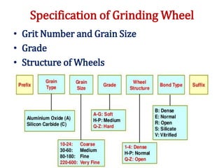
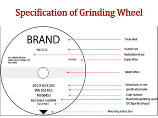
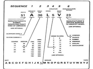
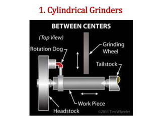
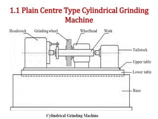
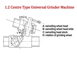
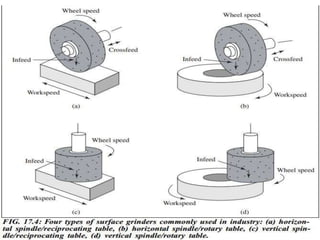
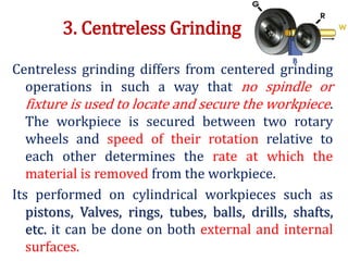
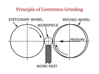
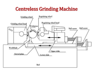
RAMCO INSTITUTE OF TECHNOLOGY
Mr.M.LAKSHMANAN
Assistant Professor (Senior Grade)
Department of Mechanical Engineering
UNIT IV
ABRASIVE PROCESS AND
BROACHING
UNIT -IV ABRASIVE PROCESS AND BROACHING -
Syllabus
Abrasive processes: grinding wheel – specifications and
selection, types of grinding process– cylindrical
grinding, surface grinding, centre less grinding and
internal grinding- Typical applications – concepts of
surface integrity, broaching machines: broach
construction – push, pull surface and continuous
broaching machines.
Grinding
Grinding is one of the abrasive processes. It’s a
metal cutting process in which the metal is
removed with the help of rotating grinding
wheel. This process removes comparatively
little material usually from 0.25mm to 0.5mm.
It is a metal cutting operation performed by
means of a rotating abrasive tool, called
Grinding wheel.
Such wheels are made of fine grains of
abrasive materials held together by a bonding
materials called a bond.
Grinding Wheel
Grinding wheels are made up of small abrasive
particles held together by bonding materials.
Thus it forms a multi edge cutter.
Grinding Wheel Abrasives:
Abrasive is a hard material. Its used to cut or
wear away other materials. Small sizes of
abrasives particles are used in grinding
wheels. They are called Abrasive Grains.
Types of Abrasive Materials
1.Natural abrasives
2.Artificial abrasives
1. Natural abrasives:
These are produced by uncontrolled forces of nature.
These are obtained from mines.
• Solid quartz(sio2)
• Emery (mixture of 50-60% Alumina + iron
oxide)coated paper
• Corundum (75-90% Crystalline Al2o3 + iron oxide)
• Diamond
Natural abrasives lack of uniformity of properties and the
reliability has largely been replaced by Artificial
abrasive.
2. Artificial abrasives:
Its manufactured under controlled conditions in
closed electric furnace in order to avoid the
introduction of impurities and to achieve the
necessary temperature for the chemical reaction
to take place. These abrasives have better cutting
properties and higher efficiency than natural
abrasives. The various manufactured abrasives
are:
• Silicon carbide
• Aluminum oxide
• Boron carbide
• Cubic boron nitride
Silicon carbide (SiC):
• Silica sand+ petroleum coke + salt mixed
• 2000°c to 4000°c for 34 hours
• Brittle
• Used for low tensile strength such as cast iron,
brass, copper, aluminum.
SiO2 + 3C = SiC + 2CO
Aluminum oxide (Al2O3):
• Very hard and tough grains having sharp
cutting edges.
• Bauxide + Coke + Iron scrap
• Electric furnace
• Tough, less brittle and high tensile strength
• Used for high speed steel, malleable cast iron,
wrought iron etc.
Boron Carbide (B4C):
• It is harder than silicon carbide but not as hard as
diamond
• Coke + boric acid
• Electric furnace
• Used for grinding and lapping very hard metals,
hard alloys, glass and jewels.
Cubic Boron Nitride (CBN):
• It is harder than Aluminum oxide
• Boron + Nitrogen
• Nitrogen atoms
• Thermal resistance
• Grinding HSS cutters, tool steels, punch press dies,
hardenable stainless steels
BOND
Bond is an adhesive substance which holds the
abrasive grains together to form the grinding
wheel. The bonds must sufficiently be strong to
withstand the stresses of high speed rotating
grinding wheel.
Types of Bonds:
1. Organic Bonds
 Resinoid
 Rubber
 Shellac
 Oxychloride
2. Non Organic Bonds
 Vitrified
 Silicate
Non Organic Bonds
Vitrified bond (V):
• Clay+ Abrasive grains mixed with water
• 715°c
• Very strong
• Acids and alkalis not affected
• Brittleness
• Long time
Silicate bond (S):
• Abrasive grains + silicate of soda
• 270°c for 20 to 80 hours.
• Water proof
• Wear quickly
• Blades, grinding cutter
• Large wheels upto 1500mm diameter can
easily be produced.
Organic Bonds
Resinoid / Bakelite bond (B):
• Abrasive grains+ mixed with natural resin
• 210°c to250°
• Grinding Cams
• High finish on the work piece
• Speed upto 300m/min
• Used in grinding of steel, cast iron,
Malleable iron castings.
Rubber bond (R):
• Abrasive grains+ Pure rubber and Sulphur
• Sulphur vulcanizing agent
• High class surface finish (Centreless Grinding)
• Wheel thick upto125mm
• Very strong and tough and close grained
Shellac bond (E):
• Abrasive grains+ coated with shellac
• Elastic bonded wheel
• 160°c to 200°c
• Very thin wheels can be produced (for Cutting off
operation)
• Cam shaft and Mill Rolls
Oxychloride bond (O):
• Abrasive grains+ mixed with Oxide and
Chloride of magnesium
• Disc shaped wheels.
• Less brittle
• Less sensitive to side loads as compared to
vitrified bond wheel
• Grinding in dry condition (Cool cutting action)
Specification of Grinding Wheel
• Grit Number and Grain Size
• Grade
• Structure of Wheels
Specification of Grinding Wheel
Grit Number and Grain Size
• It refers to the actual size of the abrasive
particles. The grain size is denoted by the grit
number. Grid Number is equal to the number
of meshes in 254 mm of a sieve through which
the grains can pass through.
• Larger is the grit number, smaller will be the
grain size (fine Grit) and vice versa.
• For rough machining, coarse grained wheels
(Smaller grit number) are used.
• For finishing, fine grained wheels (large grit
number) are used.
Grain size used for Grinding Operation
Grit
The size of the abrasive grains are indicated by
grit number or grain number.
Grinding Operation Grit number
Coarse 10 12 14 16 20 24 -
Medium 30 36 46 54 60 - -
Fine 80 100 120 150 180 - -
Very fine 220 240 280 320 400 500 600
GRADE
• The term grade refers to the bond strength.
• This is the strength with the bond holds the
abrasive grains in place.
• Grade or Hardness indicates the strength with
which the bonding material holds the abrasive
grains in the grinding wheel.
• It does not refer the hardness of abrasive
grains.
The degrees of hardness are specified by the
use of letters of the Alphabet. “A” indicates
the softest Grade whereas “Z” indicates the
hardest Grade.
Soft A B C D E F G H
Medium I J K L M N O P
Hard Q R S T U V W X Y Z
Structure of Wheels
• This term denotes the spacing between abrasive
grains or in other words the density of the wheel.
• The abrasive grains in the grinding wheel are
distributed through the bond.
• The relative spacing of abrasive is referred as
structure.
• When the spacing is small, the structure is called
Dense structure.
• When the spacing is wide, the structure is called
open structure. Structure Symbol
Dense 1 2 3 4 5 6 7 8
Open 9 10 11 12 13 14 15 or higher
Designation of Grinding Wheel
An Indian Standard Institution (IS:551 – 1954) has
specified a standard system of marking the
grinding wheels.
Elements:
• Type of abrasives
• Grain size or grit number
• Grade of the wheel
• Structure
• Type of bond
• Manufacturer’s code
Selection of grinding wheels
The following factor are to be considered.
1.Constant factor:
• Physical properties of Material to be ground
• Amount and rate of stock to be removed
• Contact area
• Type of grinding machine
2. Variable factors
• Work speed
• Wheel speed
• Condition of the grinding machine(Dry/Wet)
• Personal factors
1. Constant factor:
• The material to be ground
Abrasive
Grain size
Grade
structure
-Aluminum oxide wheel
-Coarse grain wheel
-hard grade wheel
-open structure wheel
For soft, ductile and
high tensile material
Abrasive
Grain size
Grade
structure
-silicon carbide wheel
-fine grain wheel
-soft grade wheel
-dense structure wheel
For hard and brittle
the material
• The grit and grade range for various class of
work
Class of work Grit size Grade
Rough work 14-30 Q-S
Cylindrical work 35-150 J-N
Centre less and
crankshaft
46-80 J-N
Surface grinding 20-36 G-M
Tool grinding 30-80 M-Q
Internal grinding 46-60 H-N
• Amount and rate of stock to be removed
-Coarse grain and wide spacing are used for fast
cutting.
-Fine grain and close spacing are used for fine
finish.
• Contact area
-When the contact area is small, fine grain and
close spacing
-When the contact area is large coarse grain and
wide spacing
• Type of grinding machine
-Heavy rigid machine
-Light rigid machine
2. Variable factor:
a) Work speed
-Hard wheel
-Soft wheel
b) Wheel speed
-Soft wheel
-Hard wheel
c) Condition of the grinding machine
-Dry conditions
-Wet conditions
d) Personal factor
-Skilled worker
-Unskilled worker
Reconditioning of Grinding Wheel
During grinding operation, the grinding of the wheel
are subjected to wear and the wheel loses its
cutting capacity. Grinding wheels are dressed to
restore their cutting capacity which is lost by the
phenomenon of loading and Glazing.
During the operation the chips formed get entrapped
in the inner granular space of abrasive particles.
Its called Loading.
When the bond of the abrasive is very hard, it does
not dislodge an abrasive particle. Therefore the
surface of the wheel becomes smooth and gets a
glassy like appearance. Its known as Glazing of the
wheel.
DRESSING
It’s the process of loading and breaking away the
glazed surface so that new sharp abrasive particles
are again present to work for efficient cutting is
called Dressing. The dressing is done using the tool
called Dresser.
Types of Dressing Tools:
• Star Wheel Dressing Tool
• Abrasive Stick
• Diamond Dressing Tool
Abrasive Stick
TRUING
Truing is the process of trimming the cutting
surface of the wheel to run true with the axis. By
truing the cutting surface of the worn out wheel
can be shaped to the original form.
Its also used to produce the required contour for
form grinding. Truing is done with a Diamond
Truing tool. Tis process is similar to dressing.
• The grinding face of the wheel may become
irregular.
• Hence it loses its original shape
• Truing is done to bring back the original of the
wheel.
Shapes of Grinding Wheel
Standard Shapes of Grinding Wheel Faces
Classification of Grinding Machine
• According to type of operation
 Tool Grinders
 Cut off Grinders
• According to the quality of surface finish
 Precision Grinders
 Rough Grinders
• According to the type of surface generated
 Cylindrical Grinders
 Internal Grinders
 Surface Grinders
 Tool Grinders
 Special purpose Grinding Machines
 Surface finishing Grinders
1. cylindrical grinders
 Plain cylindrical grinder
Universal cylindrical grinder
Centreless grinder
2. Internal grinders
 Plain internal grinder
Centreless internal grinder
Chucking internal grinder
Universal internal grinder
3.Surface grinder
(i) Reciprocating table
(a) Horizontal spindle
(b) Vertical spindle
(ii) Rotating table
(a) Horizontal spindle
(b) Vertical spindle
4. Tool and cutter grinder
(a) Universal
(b) Special
Rough Grinders
Its used for removing large amount of metal
from the workpiece. It is used for removing
projections such as sprue pins from casting,
projections in forging, finishing the
weldments, sharpening of hand tools.
Bench Grinder
Portable Grinder
Abrasive Belt Grinder
Swing Frame Grinder
Precision Grinders
Its used to manufacture parts of accurate
dimensions and good surface finish. The
workpiece and the grinding wheel are rigidly
mounted but they are adjustable according to
the requirement of the machining methods.
It is used for cylinder bores, gauges, tools,
cutters, machine guide ways, threads, gears,
cams etc.
1. Cylindrical Grinders
1.1 Plain Centre Type Cylindrical Grinding
Machine
1.2 Centre Type Universal Grinder Machine
2. Surface Grinders
• Horizontal Spindle Reciprocating Table Surface
Grinder
• Horizontal Spindle Rotary Table Surface
Grinder
• Vertical Spindle Reciprocating Table Surface
Grinder
• Vertical Spindle Rotary Table Surface Grinder
2.1 Horizontal Spindle Reciprocating Table
Surface Grinder
2.2 Horizontal Spindle Rotary Table Surface
Grinder
2.3 Vertical Spindle Reciprocating Table
Surface Grinder
2.4 Vertical Spindle Rotary Table Surface
Grinder
3. Centreless Grinding
Centreless grinding differs from centered grinding
operations in such a way that no spindle or
fixture is used to locate and secure the workpiece.
The workpiece is secured between two rotary
wheels and speed of their rotation relative to
each other determines the rate at which the
material is removed from the workpiece.
Its performed on cylindrical workpieces such as
pistons, Valves, rings, tubes, balls, drills, shafts,
etc. it can be done on both external and internal
surfaces.
Principle of Centreless Grinding
Centreless Grinding Machine
Methods of External Centreless Grinding
 Through Feed
 In Feed
 End Feed
1. Through Feed:
Its used for straight cylindrical workpiece such
as long shafts or bars, roller pins etc. In this
method regulating wheel is tilted at small
angle. It makes the work to move axially
through the space between grinding wheel
and regulating wheel. The guides are
provided at the ends of the wheel and guide
the movement of the workpiece.
The machine usually removes 0.2mm of stock in
one pass on the diameter of the work.
Through Feed
2. In Feed:
Its similar to plunge grinding. The work is placed
on the work rest against an end stop. It
prevents the axial movement of the workpiece.
The regulating wheel and work rest with the
workpieces are moved towards the grinding
wheel by hand feed. Its used to grind shoulders
and formed surfaces.
3. End Feed:
In this method, both grinding and regulating
wheels are tapered and thus, it produces
tapered workpieces. The workpiece is fed
lengthwise between wheels and its ground
as it advances until it reaches the end stop.
Internal Grinding
• Chucking Type
• Planetary Type
• Centreless Type
1. Chucking Type Internal Grinders
The workpiece is mounted in a chuck and
rotated about its axis. The workpiece is
mounted at the left side of the machine. The
grinding wheel (wheel head) is mounted at
the right end of the machine.
The grinding wheel is rotated and at the same
time, it reciprocates back and forth through
the length of the hole.
2. Planetary Type Internal Grinders
In this grinders, the work remains stationary
and the rotation of wheel spindle gives an
eccentric motion according to the diameter of
the hole to be ground.
Therefore in this operation, the motion of the
grinding wheel is in the form of the planet and
hence, its called planetary grinding.
3. Centreless Internal Grinding
In this centreless internal grinding, the work
is supported by three rolls.
One is the regulating wheel,
The second one is a supporting roll and the
last one is a pressure roll.
The pressure roll is used to hold the
workpiece against the support and
regulating rolls.
Advantages of Centreless Grinding
• Small diameter and long length work pieces can
be ground without any deflection as the work
piece.
• Size of job can be controlled easily and accurately.
• Suitable for mass production.
• Work holding devices like,chucks,dogs are not
possible.
Disadvantages
• It is not used for large diameter work piece
• Jobs having flat surface on cylindrical can not be
ground.
Size and specification of grinding machines
• The largest work piece which can be held on
a grinder
• The normal capacity of the grinder
• The width of the table
• The maximum traverse of the table
• Wheel diameter
• Height of the grinding head
Grinding Ratio
G= volume of material required
volume of wheel wear
Applications of Grinding Wheel
• Forming
• Gear Teeth Grinding
• Thread Grinding
• Cam Grinding
• Tool and Cutter Grinding
Surface Integrity
Surface integrity is the surface condition of a
workpiece after completing a particular
manufacturing process.
The concentrated energy consumption at the
contact region of a machining process can be
divided into Mechanical, Thermal and Chemical
effects which lead to differing intensities of
surface property alterations.
Types of Surface integrity characteristics:
Topography Characteristics – surface roughness,
waviness, errors of forms and flaws.
Surface layer Characteristics – Plastic deformation,
residual stresses, cracks, hardness, phase change,
recrystallization, etc.
Factors influence workpiece Surface Topographies
in Grinding
• Workpiece material – Harder materials allow finer
finishes
• Type of wheel – Fine Grains yield finer finishes
• Dressing procedure – Improperly dressed wheels will
damage the work surface.
• Feed rate – Finer finishes are obtained with
slower feed rates
• Machine rigidity – Older, worn machines yield a poor
quality finish
• Wheel condition – Clogged wheels cannot produce a
good finish
• Lubricant cleanliness – Coolant filtration removes waste that
could damage workpiece surface.
BROACHING
Broaching is a process of machining a surface
with a special multipoint cutting tool called
Broach which has successively higher cutting
edges in a fixed path.
It is faster and cheaper method of machining but
depth of removed material is limited to 6mm or
less. External and Internal surfaces can be
machined by broaching.
It is used to machine key ways,splines,square,
rectangular and polygon holes, internal gear
etc.
External Broaching
Internal Broaching
Specification of Broaching Machine
Main Specifications:
• Maximum length of the stroke in mm
• Maximum force developed by the slide in
Tonnes.
Minor Specifications:
• Power rating of electrical motor in H.P
• Speed and feed Range
• Weight of thee machine in Tonnes
• Floor space required in square meter.
Types of Broaching Machine
• According to the direction of the cutter
1.Horizontal 2. Vertical
• According to the method of cutting
1.Pull type 2.Push type 3. Continuous type
• According to the type of drive
1.Mechanical drive 2. Hydraulic drive
• According to the number of pull heads
1.single head 2. multiple pull head
• According to the type of operation
1.External type 2. Internal type
Horizontal Broaching Machines
1.Horizontal type Internal Broaching Machine
All Horizontal broaching machines are of pull
type and provided with either hydraulic or an
electric drive. Its operated at a low speed of 2
to 15m per minute.
Its used for small and medium sized works like
keyways and internal gears, etc.
2. Horizontal Type Surface Broaching Machine
The broach is pulled over the top surface of the
workpiece. The cutting speed ranges from 3 to
12 mpm with a return speed up to 30mpm.
Vertical Broaching Machine
1. Push Down Type
2. Pull Down Type
3. Pull Up Type
1. Push Down Type Vertical Broaching Machine
The push type vertical broaching machine is
used in the surface broaching operation. It
consists of a box shaped column, slide and
drive mechanism. The slide is provided with
a quick return mechanism.
2. Pull Down Type Vertical Broaching Machine
These machines are
mostly used for internal
broaching operations. Its
pulled through the job.
The tail end of the
broach is automatically
engaged by a pulling
mechanism and it is
pulled down through the
job.
Pull Down Type Vertical Broaching Machine
3. Pull Up Type Vertical Broaching Machine
In this type, the ram slides
on the vertical column of
the machine.
The ram carries the pulling
head at its bottom. The
broach is pulled upward.
Continuous Broaching Machines
Its used for high production rate of small
parts.
Types:
• Horizontal Type
• Vertical Type
• Rotary Type
1. Horizontal Type Continuous Broaching Machine
It is one type of surface broaching machine. It has a
driving unit which consists of two sprockets. They are
connected by an endless chain. Fixtures are mounted
at intervals on the chain for loading and holding
workpieces.
The broach is horizontally fixed in the frame of the
machine. The rigid guiding member is arranged
under the chain in the zone where the workpiece
passes under the broach. The work is automatically
clamped before it reaches the Tool.
2. Vertical Type Continuous Broaching Machine
When the axes of two sprockets are vertical. Its
called Vertical Broaching Machining. The
broach is vertically placed on the frame of the
machine.
3. Rotary Type Continuous Broaching Machine
The machine has a rotary table and vertical
column. In vertical column the broach is
horizontally fitted above the table. A series of
fixtures are mounted on the rotary table for
locating and holding workpieces.
Broach Nomenclature
The broach is composed of a series of teeth. Each
tooth is standing slightly higher than the
previous one. This rise per tooth is the feed per
tooth and it determines the material removed
by the tool.
Types of Broaching Tools
• Push Broach
• Pull Broach
• Progressive Broach
• Push Broach:
• Pull Broach:
• Progressive Broach:
Broaching Tool Materials
• High speed tool steel such as alloy steel and
stainless steel
• TiN Coated carbides
• Aluminium
• Brass
• 12L14
Applications of Broaching Machines
• Straight and helical slots
• External surfaces of various shape
• External and internal toothed gears
• Holes of cross sectional shape
HONING
Honing is an abrasive machining process that
produces a precision surface on a metal
workpiece by scrubbing an abrasive stone
against it along a controlled path. Honing is
primarily used to improve the geometric form
of a surface, but may also improve the surface
texture.
Unit IV   Abrasive Process and Broaching

Unit IV Abrasive Process and Broaching

  • 1.
    RAMCO INSTITUTE OFTECHNOLOGY Mr.M.LAKSHMANAN Assistant Professor (Senior Grade) Department of Mechanical Engineering
  • 2.
  • 3.
    UNIT -IV ABRASIVEPROCESS AND BROACHING - Syllabus Abrasive processes: grinding wheel – specifications and selection, types of grinding process– cylindrical grinding, surface grinding, centre less grinding and internal grinding- Typical applications – concepts of surface integrity, broaching machines: broach construction – push, pull surface and continuous broaching machines.
  • 4.
    Grinding Grinding is oneof the abrasive processes. It’s a metal cutting process in which the metal is removed with the help of rotating grinding wheel. This process removes comparatively little material usually from 0.25mm to 0.5mm. It is a metal cutting operation performed by means of a rotating abrasive tool, called Grinding wheel. Such wheels are made of fine grains of abrasive materials held together by a bonding materials called a bond.
  • 5.
    Grinding Wheel Grinding wheelsare made up of small abrasive particles held together by bonding materials. Thus it forms a multi edge cutter. Grinding Wheel Abrasives: Abrasive is a hard material. Its used to cut or wear away other materials. Small sizes of abrasives particles are used in grinding wheels. They are called Abrasive Grains.
  • 6.
    Types of AbrasiveMaterials 1.Natural abrasives 2.Artificial abrasives 1. Natural abrasives: These are produced by uncontrolled forces of nature. These are obtained from mines. • Solid quartz(sio2) • Emery (mixture of 50-60% Alumina + iron oxide)coated paper • Corundum (75-90% Crystalline Al2o3 + iron oxide) • Diamond Natural abrasives lack of uniformity of properties and the reliability has largely been replaced by Artificial abrasive.
  • 7.
    2. Artificial abrasives: Itsmanufactured under controlled conditions in closed electric furnace in order to avoid the introduction of impurities and to achieve the necessary temperature for the chemical reaction to take place. These abrasives have better cutting properties and higher efficiency than natural abrasives. The various manufactured abrasives are: • Silicon carbide • Aluminum oxide • Boron carbide • Cubic boron nitride
  • 8.
    Silicon carbide (SiC): •Silica sand+ petroleum coke + salt mixed • 2000°c to 4000°c for 34 hours • Brittle • Used for low tensile strength such as cast iron, brass, copper, aluminum. SiO2 + 3C = SiC + 2CO
  • 9.
    Aluminum oxide (Al2O3): •Very hard and tough grains having sharp cutting edges. • Bauxide + Coke + Iron scrap • Electric furnace • Tough, less brittle and high tensile strength • Used for high speed steel, malleable cast iron, wrought iron etc.
  • 10.
    Boron Carbide (B4C): •It is harder than silicon carbide but not as hard as diamond • Coke + boric acid • Electric furnace • Used for grinding and lapping very hard metals, hard alloys, glass and jewels. Cubic Boron Nitride (CBN): • It is harder than Aluminum oxide • Boron + Nitrogen • Nitrogen atoms • Thermal resistance • Grinding HSS cutters, tool steels, punch press dies, hardenable stainless steels
  • 11.
    BOND Bond is anadhesive substance which holds the abrasive grains together to form the grinding wheel. The bonds must sufficiently be strong to withstand the stresses of high speed rotating grinding wheel. Types of Bonds: 1. Organic Bonds  Resinoid  Rubber  Shellac  Oxychloride 2. Non Organic Bonds  Vitrified  Silicate
  • 12.
    Non Organic Bonds Vitrifiedbond (V): • Clay+ Abrasive grains mixed with water • 715°c • Very strong • Acids and alkalis not affected • Brittleness • Long time
  • 13.
    Silicate bond (S): •Abrasive grains + silicate of soda • 270°c for 20 to 80 hours. • Water proof • Wear quickly • Blades, grinding cutter • Large wheels upto 1500mm diameter can easily be produced.
  • 14.
    Organic Bonds Resinoid /Bakelite bond (B): • Abrasive grains+ mixed with natural resin • 210°c to250° • Grinding Cams • High finish on the work piece • Speed upto 300m/min • Used in grinding of steel, cast iron, Malleable iron castings.
  • 15.
    Rubber bond (R): •Abrasive grains+ Pure rubber and Sulphur • Sulphur vulcanizing agent • High class surface finish (Centreless Grinding) • Wheel thick upto125mm • Very strong and tough and close grained Shellac bond (E): • Abrasive grains+ coated with shellac • Elastic bonded wheel • 160°c to 200°c • Very thin wheels can be produced (for Cutting off operation) • Cam shaft and Mill Rolls
  • 16.
    Oxychloride bond (O): •Abrasive grains+ mixed with Oxide and Chloride of magnesium • Disc shaped wheels. • Less brittle • Less sensitive to side loads as compared to vitrified bond wheel • Grinding in dry condition (Cool cutting action)
  • 17.
    Specification of GrindingWheel • Grit Number and Grain Size • Grade • Structure of Wheels
  • 18.
  • 19.
    Grit Number andGrain Size • It refers to the actual size of the abrasive particles. The grain size is denoted by the grit number. Grid Number is equal to the number of meshes in 254 mm of a sieve through which the grains can pass through. • Larger is the grit number, smaller will be the grain size (fine Grit) and vice versa. • For rough machining, coarse grained wheels (Smaller grit number) are used. • For finishing, fine grained wheels (large grit number) are used.
  • 20.
    Grain size usedfor Grinding Operation Grit The size of the abrasive grains are indicated by grit number or grain number. Grinding Operation Grit number Coarse 10 12 14 16 20 24 - Medium 30 36 46 54 60 - - Fine 80 100 120 150 180 - - Very fine 220 240 280 320 400 500 600
  • 21.
    GRADE • The termgrade refers to the bond strength. • This is the strength with the bond holds the abrasive grains in place. • Grade or Hardness indicates the strength with which the bonding material holds the abrasive grains in the grinding wheel. • It does not refer the hardness of abrasive grains.
  • 22.
    The degrees ofhardness are specified by the use of letters of the Alphabet. “A” indicates the softest Grade whereas “Z” indicates the hardest Grade. Soft A B C D E F G H Medium I J K L M N O P Hard Q R S T U V W X Y Z
  • 23.
    Structure of Wheels •This term denotes the spacing between abrasive grains or in other words the density of the wheel. • The abrasive grains in the grinding wheel are distributed through the bond. • The relative spacing of abrasive is referred as structure. • When the spacing is small, the structure is called Dense structure. • When the spacing is wide, the structure is called open structure. Structure Symbol Dense 1 2 3 4 5 6 7 8 Open 9 10 11 12 13 14 15 or higher
  • 24.
    Designation of GrindingWheel An Indian Standard Institution (IS:551 – 1954) has specified a standard system of marking the grinding wheels. Elements: • Type of abrasives • Grain size or grit number • Grade of the wheel • Structure • Type of bond • Manufacturer’s code
  • 26.
    Selection of grindingwheels The following factor are to be considered. 1.Constant factor: • Physical properties of Material to be ground • Amount and rate of stock to be removed • Contact area • Type of grinding machine
  • 27.
    2. Variable factors •Work speed • Wheel speed • Condition of the grinding machine(Dry/Wet) • Personal factors
  • 28.
    1. Constant factor: •The material to be ground Abrasive Grain size Grade structure -Aluminum oxide wheel -Coarse grain wheel -hard grade wheel -open structure wheel For soft, ductile and high tensile material Abrasive Grain size Grade structure -silicon carbide wheel -fine grain wheel -soft grade wheel -dense structure wheel For hard and brittle the material
  • 29.
    • The gritand grade range for various class of work Class of work Grit size Grade Rough work 14-30 Q-S Cylindrical work 35-150 J-N Centre less and crankshaft 46-80 J-N Surface grinding 20-36 G-M Tool grinding 30-80 M-Q Internal grinding 46-60 H-N
  • 30.
    • Amount andrate of stock to be removed -Coarse grain and wide spacing are used for fast cutting. -Fine grain and close spacing are used for fine finish. • Contact area -When the contact area is small, fine grain and close spacing -When the contact area is large coarse grain and wide spacing
  • 31.
    • Type ofgrinding machine -Heavy rigid machine -Light rigid machine 2. Variable factor: a) Work speed -Hard wheel -Soft wheel
  • 32.
    b) Wheel speed -Softwheel -Hard wheel c) Condition of the grinding machine -Dry conditions -Wet conditions d) Personal factor -Skilled worker -Unskilled worker
  • 33.
    Reconditioning of GrindingWheel During grinding operation, the grinding of the wheel are subjected to wear and the wheel loses its cutting capacity. Grinding wheels are dressed to restore their cutting capacity which is lost by the phenomenon of loading and Glazing. During the operation the chips formed get entrapped in the inner granular space of abrasive particles. Its called Loading. When the bond of the abrasive is very hard, it does not dislodge an abrasive particle. Therefore the surface of the wheel becomes smooth and gets a glassy like appearance. Its known as Glazing of the wheel.
  • 34.
    DRESSING It’s the processof loading and breaking away the glazed surface so that new sharp abrasive particles are again present to work for efficient cutting is called Dressing. The dressing is done using the tool called Dresser. Types of Dressing Tools: • Star Wheel Dressing Tool • Abrasive Stick • Diamond Dressing Tool
  • 36.
  • 39.
    TRUING Truing is theprocess of trimming the cutting surface of the wheel to run true with the axis. By truing the cutting surface of the worn out wheel can be shaped to the original form. Its also used to produce the required contour for form grinding. Truing is done with a Diamond Truing tool. Tis process is similar to dressing.
  • 41.
    • The grindingface of the wheel may become irregular. • Hence it loses its original shape • Truing is done to bring back the original of the wheel.
  • 42.
  • 43.
    Standard Shapes ofGrinding Wheel Faces
  • 44.
    Classification of GrindingMachine • According to type of operation  Tool Grinders  Cut off Grinders • According to the quality of surface finish  Precision Grinders  Rough Grinders • According to the type of surface generated  Cylindrical Grinders  Internal Grinders  Surface Grinders  Tool Grinders  Special purpose Grinding Machines  Surface finishing Grinders
  • 45.
    1. cylindrical grinders Plain cylindrical grinder Universal cylindrical grinder Centreless grinder 2. Internal grinders  Plain internal grinder Centreless internal grinder Chucking internal grinder Universal internal grinder
  • 46.
    3.Surface grinder (i) Reciprocatingtable (a) Horizontal spindle (b) Vertical spindle (ii) Rotating table (a) Horizontal spindle (b) Vertical spindle 4. Tool and cutter grinder (a) Universal (b) Special
  • 47.
    Rough Grinders Its usedfor removing large amount of metal from the workpiece. It is used for removing projections such as sprue pins from casting, projections in forging, finishing the weldments, sharpening of hand tools.
  • 48.
  • 49.
  • 50.
  • 51.
  • 52.
    Precision Grinders Its usedto manufacture parts of accurate dimensions and good surface finish. The workpiece and the grinding wheel are rigidly mounted but they are adjustable according to the requirement of the machining methods. It is used for cylinder bores, gauges, tools, cutters, machine guide ways, threads, gears, cams etc.
  • 53.
  • 54.
    1.1 Plain CentreType Cylindrical Grinding Machine
  • 55.
    1.2 Centre TypeUniversal Grinder Machine
  • 56.
    2. Surface Grinders •Horizontal Spindle Reciprocating Table Surface Grinder • Horizontal Spindle Rotary Table Surface Grinder • Vertical Spindle Reciprocating Table Surface Grinder • Vertical Spindle Rotary Table Surface Grinder
  • 57.
    2.1 Horizontal SpindleReciprocating Table Surface Grinder
  • 60.
    2.2 Horizontal SpindleRotary Table Surface Grinder
  • 61.
    2.3 Vertical SpindleReciprocating Table Surface Grinder
  • 63.
    2.4 Vertical SpindleRotary Table Surface Grinder
  • 66.
    3. Centreless Grinding Centrelessgrinding differs from centered grinding operations in such a way that no spindle or fixture is used to locate and secure the workpiece. The workpiece is secured between two rotary wheels and speed of their rotation relative to each other determines the rate at which the material is removed from the workpiece. Its performed on cylindrical workpieces such as pistons, Valves, rings, tubes, balls, drills, shafts, etc. it can be done on both external and internal surfaces.
  • 67.
  • 68.
  • 69.
  • 70.
    Methods of ExternalCentreless Grinding  Through Feed  In Feed  End Feed
  • 71.
    1. Through Feed: Itsused for straight cylindrical workpiece such as long shafts or bars, roller pins etc. In this method regulating wheel is tilted at small angle. It makes the work to move axially through the space between grinding wheel and regulating wheel. The guides are provided at the ends of the wheel and guide the movement of the workpiece. The machine usually removes 0.2mm of stock in one pass on the diameter of the work.
  • 72.
  • 73.
    2. In Feed: Itssimilar to plunge grinding. The work is placed on the work rest against an end stop. It prevents the axial movement of the workpiece. The regulating wheel and work rest with the workpieces are moved towards the grinding wheel by hand feed. Its used to grind shoulders and formed surfaces.
  • 74.
    3. End Feed: Inthis method, both grinding and regulating wheels are tapered and thus, it produces tapered workpieces. The workpiece is fed lengthwise between wheels and its ground as it advances until it reaches the end stop.
  • 75.
    Internal Grinding • ChuckingType • Planetary Type • Centreless Type
  • 76.
    1. Chucking TypeInternal Grinders The workpiece is mounted in a chuck and rotated about its axis. The workpiece is mounted at the left side of the machine. The grinding wheel (wheel head) is mounted at the right end of the machine. The grinding wheel is rotated and at the same time, it reciprocates back and forth through the length of the hole.
  • 78.
    2. Planetary TypeInternal Grinders In this grinders, the work remains stationary and the rotation of wheel spindle gives an eccentric motion according to the diameter of the hole to be ground. Therefore in this operation, the motion of the grinding wheel is in the form of the planet and hence, its called planetary grinding.
  • 79.
  • 80.
    In this centrelessinternal grinding, the work is supported by three rolls. One is the regulating wheel, The second one is a supporting roll and the last one is a pressure roll. The pressure roll is used to hold the workpiece against the support and regulating rolls.
  • 82.
    Advantages of CentrelessGrinding • Small diameter and long length work pieces can be ground without any deflection as the work piece. • Size of job can be controlled easily and accurately. • Suitable for mass production. • Work holding devices like,chucks,dogs are not possible. Disadvantages • It is not used for large diameter work piece • Jobs having flat surface on cylindrical can not be ground.
  • 83.
    Size and specificationof grinding machines • The largest work piece which can be held on a grinder • The normal capacity of the grinder • The width of the table • The maximum traverse of the table • Wheel diameter • Height of the grinding head
  • 84.
    Grinding Ratio G= volumeof material required volume of wheel wear
  • 85.
    Applications of GrindingWheel • Forming • Gear Teeth Grinding • Thread Grinding • Cam Grinding • Tool and Cutter Grinding
  • 87.
    Surface Integrity Surface integrityis the surface condition of a workpiece after completing a particular manufacturing process. The concentrated energy consumption at the contact region of a machining process can be divided into Mechanical, Thermal and Chemical effects which lead to differing intensities of surface property alterations. Types of Surface integrity characteristics: Topography Characteristics – surface roughness, waviness, errors of forms and flaws. Surface layer Characteristics – Plastic deformation, residual stresses, cracks, hardness, phase change, recrystallization, etc.
  • 88.
    Factors influence workpieceSurface Topographies in Grinding • Workpiece material – Harder materials allow finer finishes • Type of wheel – Fine Grains yield finer finishes • Dressing procedure – Improperly dressed wheels will damage the work surface. • Feed rate – Finer finishes are obtained with slower feed rates • Machine rigidity – Older, worn machines yield a poor quality finish • Wheel condition – Clogged wheels cannot produce a good finish • Lubricant cleanliness – Coolant filtration removes waste that could damage workpiece surface.
  • 89.
    BROACHING Broaching is aprocess of machining a surface with a special multipoint cutting tool called Broach which has successively higher cutting edges in a fixed path. It is faster and cheaper method of machining but depth of removed material is limited to 6mm or less. External and Internal surfaces can be machined by broaching. It is used to machine key ways,splines,square, rectangular and polygon holes, internal gear etc.
  • 90.
  • 92.
  • 94.
    Specification of BroachingMachine Main Specifications: • Maximum length of the stroke in mm • Maximum force developed by the slide in Tonnes. Minor Specifications: • Power rating of electrical motor in H.P • Speed and feed Range • Weight of thee machine in Tonnes • Floor space required in square meter.
  • 95.
    Types of BroachingMachine • According to the direction of the cutter 1.Horizontal 2. Vertical • According to the method of cutting 1.Pull type 2.Push type 3. Continuous type • According to the type of drive 1.Mechanical drive 2. Hydraulic drive • According to the number of pull heads 1.single head 2. multiple pull head • According to the type of operation 1.External type 2. Internal type
  • 96.
    Horizontal Broaching Machines 1.Horizontaltype Internal Broaching Machine
  • 97.
    All Horizontal broachingmachines are of pull type and provided with either hydraulic or an electric drive. Its operated at a low speed of 2 to 15m per minute. Its used for small and medium sized works like keyways and internal gears, etc.
  • 99.
    2. Horizontal TypeSurface Broaching Machine The broach is pulled over the top surface of the workpiece. The cutting speed ranges from 3 to 12 mpm with a return speed up to 30mpm.
  • 100.
    Vertical Broaching Machine 1.Push Down Type 2. Pull Down Type 3. Pull Up Type 1. Push Down Type Vertical Broaching Machine The push type vertical broaching machine is used in the surface broaching operation. It consists of a box shaped column, slide and drive mechanism. The slide is provided with a quick return mechanism.
  • 103.
    2. Pull DownType Vertical Broaching Machine These machines are mostly used for internal broaching operations. Its pulled through the job. The tail end of the broach is automatically engaged by a pulling mechanism and it is pulled down through the job.
  • 104.
    Pull Down TypeVertical Broaching Machine
  • 105.
    3. Pull UpType Vertical Broaching Machine In this type, the ram slides on the vertical column of the machine. The ram carries the pulling head at its bottom. The broach is pulled upward.
  • 106.
    Continuous Broaching Machines Itsused for high production rate of small parts. Types: • Horizontal Type • Vertical Type • Rotary Type
  • 107.
    1. Horizontal TypeContinuous Broaching Machine It is one type of surface broaching machine. It has a driving unit which consists of two sprockets. They are connected by an endless chain. Fixtures are mounted at intervals on the chain for loading and holding workpieces. The broach is horizontally fixed in the frame of the machine. The rigid guiding member is arranged under the chain in the zone where the workpiece passes under the broach. The work is automatically clamped before it reaches the Tool.
  • 109.
    2. Vertical TypeContinuous Broaching Machine When the axes of two sprockets are vertical. Its called Vertical Broaching Machining. The broach is vertically placed on the frame of the machine.
  • 110.
    3. Rotary TypeContinuous Broaching Machine The machine has a rotary table and vertical column. In vertical column the broach is horizontally fitted above the table. A series of fixtures are mounted on the rotary table for locating and holding workpieces.
  • 111.
    Broach Nomenclature The broachis composed of a series of teeth. Each tooth is standing slightly higher than the previous one. This rise per tooth is the feed per tooth and it determines the material removed by the tool.
  • 113.
    Types of BroachingTools • Push Broach • Pull Broach • Progressive Broach • Push Broach:
  • 114.
  • 115.
  • 116.
    Broaching Tool Materials •High speed tool steel such as alloy steel and stainless steel • TiN Coated carbides • Aluminium • Brass • 12L14
  • 117.
    Applications of BroachingMachines • Straight and helical slots • External surfaces of various shape • External and internal toothed gears • Holes of cross sectional shape
  • 118.
    HONING Honing is anabrasive machining process that produces a precision surface on a metal workpiece by scrubbing an abrasive stone against it along a controlled path. Honing is primarily used to improve the geometric form of a surface, but may also improve the surface texture.