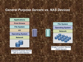
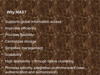
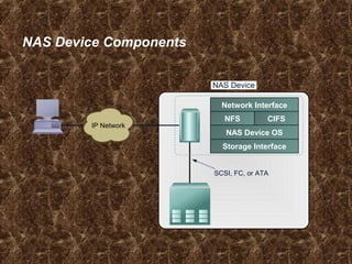
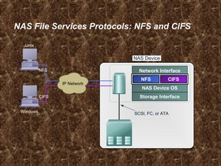
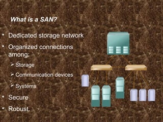
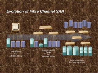
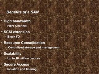
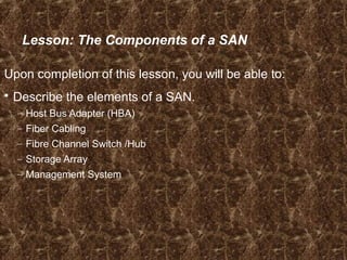
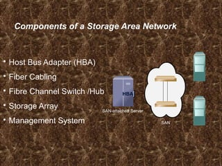
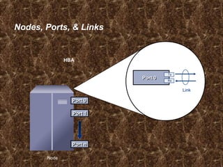
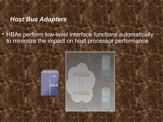
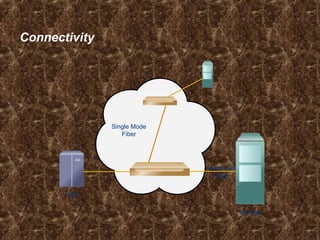
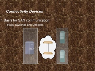
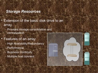
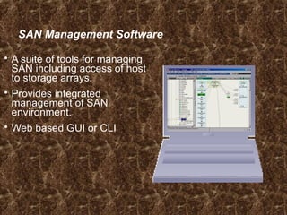
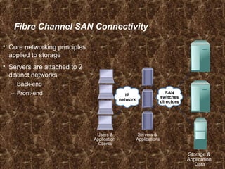
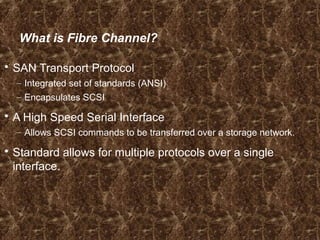
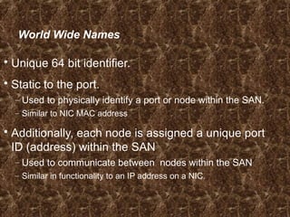
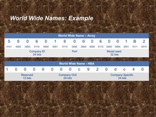
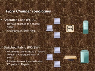
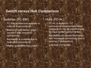
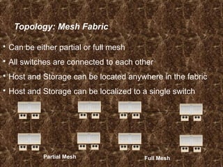
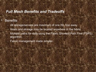
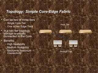
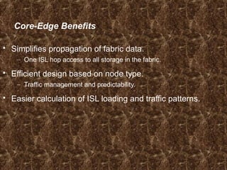
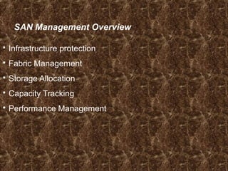
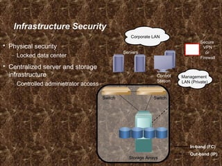
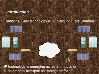
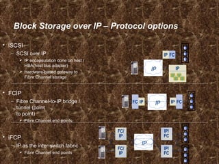
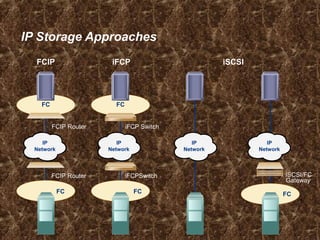
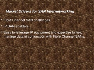
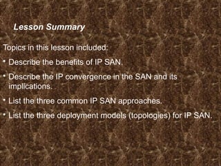
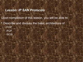
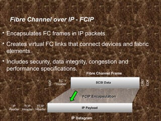
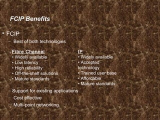
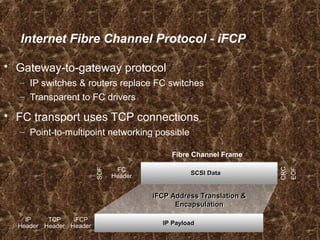
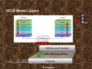
Section 3 – Networked Storage
Introduction
Section Objectives
Upon completion of this section, you will be able to:
 Describe the elements, connectivity, and management of:
Direct Attached Storage (DAS), Network Attached
Storage (NAS), FC and IP Storage Area Networks (SAN),
Content Addressed Storage (CAS)
 Compare the benefits and challenges of each of the
storage models
In this Section …
This section contains the following modules:
1. Direct Attached Storage (DAS)
2. Networked Attached Storage (NAS)
3. Storage Area Networks (SAN)
4. IP Storage Area Networks (IP SAN)
5. Content Addressed Storage (CAS)
Direct Attached Storage (DAS)
Module 3.1
Direct Attached Storage (DAS)
After completing this module you will be able to:
 Discuss the benefits of DAS based storage strategy
 Describe the elements of DAS
 Describe the connectivity options for DAS
 Discuss DAS management considerations
 Identify the best environments for DAS solutions
DAS Benefits
 Ideal for local data provisioning
 Quick deployment for small environments
 Simple to deploy in simple configurations
 Reliability
 Low capital expense
 Low complexity
Physical Elements of DAS
CPU
 Motherboard
 Clustered group of processors
 Processor cards
 Complete system
 Internal
 External
 Hard disk(s)
 CD-ROM drive
 Optical drive
 Removable media
 Tape devices/tape library
 RAID/intelligent array(s)
 Portable media drives
Connectivity
Storage
DAS Management: Internal
 Host provides:
– Disk partitioning (Volume management)
– File system layout
– Data addressing
 Direct Attached Storage managed individually through the
server and the OS
DAS Management: External
 Array based management
 Availability – multi-path I/O
 Lower TCO for managing data and storage Infrastructure
DAS Performance Considerations
Factors to be considered for DAS performance:
• Hard disks
• Memory cache
• Virtual memory (paging)
• Storage controllers
• Protocol supported (e.g. SCSI, FireWire, USB, etc.)
• RAID level
• Bus
Internal DAS Application Example
Hard Drive
40 Pin Ribbon Cable
Motherboard
External DAS Application Example
ESCON HBA
Cable for
external DAS
connectivity
DAS Challenges
 Hosts must be directly connected
 Data availability issues
– Many single points of failure
Bus, multiple path software, host, application
 Data slowdowns possible
– CPU congestion, caching, multi-pathing
 Volumes are not globally available to all hosts
 Scalability concerns
DAS Challenges
 Hosts must be directly connected
 Data availability
 Data slowdowns possible
– CPU congestion, caching, multi-pathing
 Scalability is limited
– Number of connectivity ports to hosts
– Number of addressable disks
– Distance limitations
 Downtime required for maintenance
Module Summary
Key points covered in this module:
 DAS can be:
– An integrated part of the host computer
– Directly connected to a single server
 DAS is made up of a CPU, connectivity, and
storage devices
– There are several options within each of these categories
 DAS connectivity uses block-level access
protocols
Check Your Knowledge
 What are the physical elements of DAS?
 Give an example of when DAS is a good solution.
 Describe internal DAS connectivity.
 Describe external DAS connectivity.
 What are some areas that you need to consider as part of
DAS management?

Network Attached Storage (NAS)
Module 3.2
NAS – Network Attached Storage
After completing this module, you will be able to:
 Discuss the benefits of NAS based storage strategy
 Describe the elements of NAS
 Discuss connectivity options for NAS
 Discuss NAS management considerations by
environment
 Identify the best environments for NAS solutions
In this Module …
This module contains the following lessons:
 What is NAS?
 Managing a NAS Environment
 NAS Application Examples
Lesson: What is NAS?
Upon completion of this lesson, you should be able to:
 Define NAS and describe its key attributes
 List the benefits of NAS
 Describe NAS connectivity
NAS Evolution
Network Attached Storage (NAS)
Stand Alone PC
Networked File SharingNetworked PCsPortable Media
for File Sharing
What is NAS?
NAS is shared storage on a network
infrastructure. Clients
Application
Server
Print
Server NAS Device
NAS Head Storage
General Purpose Servers vs. NAS Devices
Network
Operating System
I/O
File System
Print Drivers
Applications
General Purpose Server
(NT or Unix Server)
Network
Operating System
File System
Single Function Device
(NAS Server)
Why NAS?
 Supports global information access
 Improves efficiency
 Provides flexibility
 Centralizes storage
 Simplifies management
 Scalability
 High availability – through native clustering
 Provides security integration to environment (user
authentication and authorization)
NAS Device Components
NAS Device
CIFSNFS
Network Interface
Storage Interface
NAS Device OS
SCSI, FC, or ATA
IP Network
NAS File Services Protocols: NFS and CIFS
NAS Device
Network Interface
Storage Interface
NAS Device OS
SCSI, FC, or ATA
CIFSNFS
IP Network
Windows
Unix
NFS
CIFS
Network File System (NFS)
 Client/server application
 Uses RPC mechanisms over TCP protocol
 Mount points grant access to remote hierarchical file
structures for local file system structures
 Access to the mount can be controlled by permissions
Common Internet File System (CIFS)
 Public version of the Server Message Block (SMB)
protocol
 Client applications access files on a computer running
server applications that accept the SMB protocol
 Better control of files than FTP
 Potentially better access than Web browsers and HTTP
NAS Physical Elements
 Data movers/filers
 Management interface
– Configure network interfaces
– Create, mount, or export file system
– Install, configure and manage all data movers/filers
– Can be accessed locally or remotely
 Connectivity
– NAS head to storage
– NAS head to network
 Storage
Integrated vs. Gateway NAS
Integrated NAS
NAS Gateway
IP Network
IP Network
FC Fabric
NAS Head
NAS Head
Integrated NAS System
NAS Head
Storage
Direct Attach
IP Network
Gateway NAS System
Clients
Application Servers
Storage
NAS Gateway
FC Switch
IP Network
Lesson Summary
 A NAS server is an appliance optimized for file serving
functions.
 Generally it has a specialized operating system
 NAS supports multiple protocols
 NAS can be implemented as an integrated system or as a
gateway
Fibre Channel
Storage Area Networks (SAN)
Module 3.3
Fibre Channel Storage Area Networks (SAN)
Upon completion of this module, you will be able to:
 Describe the features and benefits of SAN.
 Describe the physical and logical elements of SAN.
 List common SAN topologies.
 Compare and contrast connectivity devices.
 Describe connectivity options of SAN.
 Describe the I/O flow in the SAN environment.
 List SAN management considerations.
 Describe applications of a SAN strategy.
In this module …
This module contains the following lessons:
 Fibre Channel SAN Overview.
 The Components of a SAN.
 FC SAN Connectivity.
 SAN Management.
 SAN Deployment Examples.
 Case Study and Applications of FC SAN.
Lesson: Fibre Channel SAN Overview
Upon completion of this lesson, you will be able to:
 Define a FC SAN.
 Describe the features of FC SAN based storage.
 Describe the benefits of an FC SAN based storage
strategy.
Business Needs and Technology Challenges
 Information when and where the business user needs it
 Integrate technology infrastructure with business
processes
 Flexible, resilient architecture
What is a SAN?
 Dedicated storage network
 Organized connections
among:
 Storage
 Communication devices
 Systems
 Secure
 Robust.
Evolution of Fibre Channel SAN
SAN Islands
FC
Arbitrated Loop
Interconnected
SANs
FC
Switched Fabric
Enterprise SANs
FC Switched Fabric
HUB
Benefits of a SAN
 High bandwidth
– Fibre Channel
 SCSI extension
– Block I/O
 Resource Consolidation
– Centralized storage and management
 Scalability
– Up to 16 million devices
 Secure Access
– Isolation and filtering
Lesson Summary
Topics in this lesson included:
 Definition of a SAN
 Features and Benefits of SANs
Lesson: The Components of a SAN
Upon completion of this lesson, you will be able to:
 Describe the elements of a SAN.
– Host Bus Adapter (HBA)
– Fiber Cabling
– Fibre Channel Switch /Hub
– Storage Array
– Management System
Components of a Storage Area Network
 Host Bus Adapter (HBA)
 Fiber Cabling
 Fibre Channel Switch /Hub
 Storage Array
 Management System
HBAHBA
SAN-attached Server
SAN
Nodes, Ports, & Links
Node
HBA
Port 0Port 0
Port 1Port 1
Port nPort n
Link
Port 0Port 0 Rx
Tx
HBA
Host Bus Adapters
 HBAs perform low-level interface functions automatically
to minimize the impact on host processor performance
HBA
Connectivity
Single Mode
Fiber
Storage
Multimode
Fiber
Host
Connectivity Devices
 Basis for SAN communication
– Hubs, Switches and Directors
HBA
Storage Resources
 Extension of the basic disk drive to an
array.
– Provides storage consolidation and
centralization
 Features of an array
– High Availability/Redundancy
– Performance
– Business Continuity
– Multiple host connect
HBA
SAN Management Software
 A suite of tools for managing
SAN including access of host
to storage arrays.
 Provides integrated
management of SAN
environment.
 Web based GUI or CLI
Lesson: Summary
Topics in this lesson included:
 The elements of a SAN:
– Host Bus Adapter (HBA)
– Fiber Cabling
– Fibre Channel Switch /Hub
– Storage Array
– Management System
Lesson: Fibre Channel SAN Connectivity
Upon completion of this lesson, you will be able to:
 Describe the Fibre Channel SAN connectivity method and
topologies
 Describe Fibre Channel devices
 Describe Fibre Channel communication protocols
 Describe Fibre Channel login procedures
Fibre Channel SAN Connectivity
 Core networking principles
applied to storage
 Servers are attached to 2
distinct networks
– Back-end
– Front-end
Users &
Application
Clients
Storage &
Application
Data
Servers &
Applications
SAN
switches
directors
IP
network
What is Fibre Channel?
 SAN Transport Protocol
– Integrated set of standards (ANSI)
– Encapsulates SCSI
 A High Speed Serial Interface
– Allows SCSI commands to be transferred over a storage network.
 Standard allows for multiple protocols over a single
interface.
World Wide Names
 Unique 64 bit identifier.
 Static to the port.
– Used to physically identify a port or node within the SAN.
– Similar to NIC MAC address
 Additionally, each node is assigned a unique port
ID (address) within the SAN
– Used to communicate between nodes within the SAN
– Similar in functionality to an IP address on a NIC.
World Wide Names: Example
World Wide Name - HBA
1 0 0 0 0 0 0 0 c 9 2 0 d c 4 0
Reserved
12 bits
Company OUI
24 bits
Company Specific
24 bits
World Wide Name – Array
5 0 0 6 0 1 6 0 0 0 6 0 0 1 B 2
0101 0000 0000 0110 0000 0001 0110 0000 0000 0000 0110 0000 0000 0001 1011 0010
Company ID
24 bits
Port Model seed
32 bits
Fibre Channel Addressing
 Fibre Channel addresses are used for transporting
frames from source ports to destination ports.
 Address assignment method varies with the associated
topology (loop vs switch)
– Loop – self assigning
– Switch – centralized authority
 Certain addresses are reserved
– FFFFFC is Name Server
– FFFFFE is Fabric Login
What is a Fabric?
 Virtual space used by nodes to
communicate with each other
once they are joined.
 Component identifiers:
– Domain ID
– Worldwide Name (WWN)
Fabric
Fibre Channel Topologies
 Arbitrated Loop (FC-AL)
– Devices attached to a shared
“loop”
– Analogous to Token Ring
 Switched Fabric (FC-SW)
– All devices connected to a “Fabric
Switch” – Analogous to an IP
switch
– Initiators have unique dedicated
I/O paths to Targets
Switch
HUB
Switch versus Hub Comparison
 Switches (FC-SW)
– FC-SW architecture scalable to
millions of connections.
– Bandwidth per device stays
constant with increased
connectivity.
– Bandwidth is scalable due to
dedicated connections.
– Higher availability than hubs.
 Hubs (FC-AL)
– FC-AL is limited to 127
connections (substantially fewer
connections can be implemented
for ideal system performance).
– Bandwidth per device diminishes
with increased connectivity due to
sharing of connections.
– Low cost connection.
Topology: Mesh Fabric
 Can be either partial or full mesh
 All switches are connected to each other
 Host and Storage can be located anywhere in the fabric
 Host and Storage can be localized to a single switch
Partial Mesh Full Mesh
Full Mesh Benefits and Tradeoffs
 Benefits
– All storage/servers are maximum of one ISL hop away.
– Hosts and storage may be located anywhere in the fabric.
– Multiple paths for data using the Fabric Shortest Path First (FSPS)
algorithm.
– Fabric management made simpler.
Topology: Simple Core-Edge Fabric
 Can be two or three tiers
– Single Core Tier
– One or two Edge Tiers
 In a two tier topology,
storage is usually
connected to the Core
 Benefits
– High Availability
– Medium Scalability
– Medium to maximum
Connectivity
Storage Tier
Host Tier
Core-Edge Benefits
 Simplifies propagation of fabric data.
– One ISL hop access to all storage in the fabric.
 Efficient design based on node type.
– Traffic management and predictability.
 Easier calculation of ISL loading and traffic patterns.
Lesson: Summary
 Topics in this lesson included:
 The Fibre Channel SAN connectivity methods and
topologies
 Fibre Channel devices
 Fibre Channel communication protocols
 Fibre Channel login procedures
Lesson: SAN Management
Upon completion of this lesson, you will be able to:
 Describe SAN management functions
– Infrastructure protection
– Provisioning
– Capacity Management
– Performance Management
SAN Management Overview
 Infrastructure protection
 Fabric Management
 Storage Allocation
 Capacity Tracking
 Performance Management
Infrastructure Security
 Physical security
– Locked data center
 Centralized server and storage
infrastructure
– Controlled administrator access
Storage Arrays
Switch Switch
Secure
VPN
or
Firewall
Servers
Control
Station
Corporate LAN
Management
LAN (Private)
In-band (FC)
Out-band (IP)
Switch/Fabric Management Tools
 Vendor supplied management software
– Embedded within the switch
– Graphical User Interface (GUI) or Command Line Interface (CLI)
 Functionality
– Common functions
Performance monitoring
Discovery
Access Management (Zoning)
– Different “look and feel” between vendors
 Additional third party software add-ons
– Enhanced functionality, such as automation
Fabric Management: Zoning
Zoning Components
Zone Zone Zone
Zones
(Library)
Zone SetZones Sets
(Library)
Members
(WWN’s) Member Member Member MemberMember Member
Provisioning: LUN Masking
 Restricts volume access to
specific hosts and/or
host clusters.
 Servers can only access the
volumes that they are assigned.
 Access controlled in the storage
and not in the fabric
– Makes distributed administration
secure
 Tools to manage masking
– GUI
– Command Line
Capacity Management
 Tracking and managing assets
– Number of ports assigned
– Storage allocated
 Utilization profile
– Indicates the percent usage of a given resource over time
– Allows for forecasting
 SAN management software provides the tools
– Inventory databases
– Report writers
Performance Management
 What is it?
– Capturing metrics and monitoring trends
– Proactively or Reactively responding
– Planning for future growth
 Areas and functions
– Host, Fabric and Storage Performance
– Building baselines for the environment
Lesson: Summary
 Topics in this lesson included:
– Infrastructure protection
– Provisioning
– Capacity Management
– Performance Management
Internet Protocol
Storage Area Networks (IP SAN)
Module 3.4
IP Storage Area Networks
Upon completion of this module, you will be able to:
 Describe the benefits of IP SAN.
 Describe IP convergence in the SAN and its implications.
 Describe and discuss the basic architecture of
– FCIP
– iFCP
– iSCSI
 Explain potential applications of IP SAN technology.
In this module …
This module contains the following lessons:
 IP SAN Overview.
 IP SAN Protocols.
 Applications of IP SAN.
Lesson: IP SAN Overview
Upon completion of this lesson, you will be able to:
 Describe the benefits of IP SAN.
 Describe the IP convergence in the SAN and its
implications.
 List the three common IP SAN approaches.
 List the three deployment models (topologies) for IP SAN.
Introduction
 Traditional SAN technology is built around Fibre Channel.
 IP technology is emerging as an alternative or
supplemental transport for storage traffic.
= IP
= FC
FCFC IPIP IPIP FCFCIP
FC/
IP
FC/
IP
FC/
IP
FC/
IP
IP
IP/
FC
IP/
FC
IP/
FC
IP/
FC
Block Storage over IP – Protocol options
 iSCSI
– SCSI over IP
 IP encapsulation done on host /
HBA(host bus adapter)
 Hardware-based gateway to
Fibre Channel storage
 FCIP
– Fibre Channel-to-IP bridge /
tunnel (point
to point)
 Fibre Channel end points
 iFCP
– IP as the inter-switch fabric
 Fibre Channel end points
IPIPIP
IPIP FCFC
IP Storage Approaches
iSCSI
FCFC
FC
FC
FC
IP
Network
IP
Network
IP
Network
IP
Network
iFCPFCIP
iFCP Switch
iFCPSwitch
FCIP Router
FCIP Router iSCSI/FC
Gateway
Market Drivers for SAN Internetworking
 Fibre Channel SAN challenges.
 IP SAN enablers.
 Easy to leverage IP equipment and expertise to help
manage data in conjunction with Fibre Channel SANs.
Benefits of IP SAN
 Cost Effective
 Extend the reach of a SAN
IP is Cost Effective
 Most organizations already have IP networks and
familiarity with traditional network management.
 Leverages existing Fibre Channel applications.
Extend the Reach of Your SAN
 Standard Fibre Channel Distances.
 IP Extends Fibre Channel applications over
regional/global distances.
 At higher link speeds, IP can handle synchronous
applications.
Lesson Summary
Topics in this lesson included:
 Describe the benefits of IP SAN.
 Describe the IP convergence in the SAN and its
implications.
 List the three common IP SAN approaches.
 List the three deployment models (topologies) for IP SAN.
Lesson: IP SAN Protocols
Upon completion of this lesson, you will be able to:
 Describe and discuss the basic architecture of
– FCIP
– iFCP
– iSCSI
Fibre Channel over IP - FCIP
 Encapsulates FC frames in IP packets.
 Creates virtual FC links that connect devices and fabric
elements.
 Includes security, data integrity, congestion and
performance specifications.
IP Datagram
IP
Header
TCP
Header
FCIP
Header IP PayloadIP Payload
Fibre Channel Frame
SOF
FC
Header
CRC
EOF
SCSI DataSCSI Data
FCIP EncapsulationFCIP Encapsulation
FCIP Benefits
 FCIP
– Best of both technologies
– Support for existing applications
– Cost effective
– Multi-point networking
Fibre Channel
• Widely available
• Low latency
• High reliability
• Off-the-shelf solutions
• Mature standards
IP
• Widely available
• Accepted
technology
• Trained user base
• Affordable
• Mature standards
Internet Fibre Channel Protocol - iFCP
 Gateway-to-gateway protocol
– IP switches & routers replace FC switches
– Transparent to FC drivers
 FC transport uses TCP connections
– Point-to-multipoint networking possible
IP
Header
TCP
Header
iFCP
Header IP PayloadIP Payload
Fibre Channel Frame
SOF
FC
Header
CRC
EOF
SCSI DataSCSI Data
iFCP Address Translation &
Encapsulation
iFCP Address Translation &
Encapsulation
iFCP Benefits
 Works with wide range of devices.
 Flexible.
 Less potential bottlenecking vs. FCIP.
iSCSI
 A method to transfer blocks of data using the TCP/IP
network.
 Serialized service delivery subsystem.
 SCSI protocol over IP.
iSCSI Model Layers
IP
Header
TCP
Header
iSCSI
Header
IP PayloadIP Payload
SCSI DataSCSI Command Descriptor
SCSI CDB encapsulation
IP Datagram
Storage
Lesson Summary
Topics in this lesson included:
 The basic architecture of FCIP.
 The basic architecture of iFCP.
 The basic architecture of iSCSI.
Content Addressed Storage (CAS)
Module 3.5
Content Addressed Storage (CAS)
Upon completion of this module, you will be able to:
 Describe the features and benefits of a CAS based
storage strategy.
 List the physical and logical elements of CAS.
 Describe the storage and retrieval process for CAS data
objects.
 Describe the best environments for CAS solutions.
In this Module …
This module contains the following lessons:
 CAS Description and Benefits
 Elements of CAS
 Data Object Storage and Retrieval
 CAS Applications and Case Scenarios
Lesson: CAS Description and Benefits
Upon completion of this lesson, you be able to:
 Define CAS.
 Describe the key attributes of CAS.
 List the features, benefits and drawbacks of CAS.
What is Content Addressed Storage (CAS)?
 Object-oriented, location-independent approach to data
storage.
 Repository for the “Objects”.
 Access mechanism to interface with repository.
 Globally unique identifiers provide access to objects.
 Extensible metadata that enables automated data
management practices and applications.
What Is Fixed Content?
Electronic Documents
• Contracts, claims, etc.
• E-mail and attachments
• Financial spread sheets
• CAD/CAM designs
• Presentations
Digital Records
• Documents
– Checks, securities trades
– Historical preservation
• Photographs
– Personal / professional
• Geophysical
– Seismic, astronomic,
geographic
Digital Assets Retained For Active Reference And Value
Leverage
Historical Value
Improve
Service Levels
Generate
New Revenues
Rich Media
• Medical
– X-rays, MRIs, CTI
• Video
– News / media, movies
– Security serveillance
• Audio
– Voicemail
– Radio
Challenges of Storing Fixed Content
 Most new digital content is fixed content.
 Fixed content is growing at more than 90%
annually.
 Long-term preservation is required (years-
decades).
 Simultaneous multi-user access.
 Need for faster access to records for business and
legal reasons.
 Need for location independent data, enabling
technology refresh and migration.
 Emerging regulations require retention.

Shortcomings of Traditional Storage Options
 Tape is slow, and standards are always changing.
 Optical is expensive, and requires vast amounts of media
in order to store data of any size.
 Many times companies retire tape products without
warning.
 Many times recovering files from tape and optical is time
consuming.
 Data on tape and optical is subject to media degradation.
Benefits of CAS
 Immutability and authentication
 Location independence
 Single instance storage
 Faster record retrieval
 Record-level retention,
protection and disposition
 Technology independence
 Online (like Disk)
 Optimized TCO
 Scalability
Drawbacks of CAS
There are some drawbacks with CAS:
 Can be slower than SAN, NAS, or DAS.
 Application integration.
 Initial cost of ownership is higher even though TCO is
significantly lower.
Lesson: Summary
Key points covered in this lesson:
 CAS Definition
 CAS Description
 Benefits and Drawbacks
Lesson: Elements of CAS
Upon completion of this lesson, you will be able to:
 Describe the Physical Elements of CAS.
 Describe the Logical Elements of CAS.
 Storage devices (CAS Based)
 Servers (to which storage devices get connected)
 Client
Physical Elements of CAS
API
ServerClient CAS-based
Storage
Logical Elements of CAS
 The Logical Elements of CAS include the Object-Level
Access Protocols.
CAS
API
API
Metadata
39HLTTT2H0404EU6M4A9MUR7TE4
Content Address
Lesson Summary
Key points covered in this lesson:
 Physical Elements of CAS
 Logical Elements of CAS
Lesson: Data Object Storage and Retrieval
Upon completion of this lesson, you will be able to:
 Describe how data gets stored in a CAS environment.
 Describe how data is retrieved from a CAS environment.
How CAS Stores a Data Object
API
Application Server
Client
CAS
Object ID
Client presents data
to API to be archived
1
Unique Content
Address is calculated
2
Object is sent to CAS
via CAS API over IP
3
CAS authenticates the
Content Address and
stores the object
4
Acknowledgement
returned to application
5
Object-ID is retained
and stored for future use
6
How CAS Retrieves a Data Object
Application Server
Client
CAS
Object is needed by
an application
1 CAS authenticates
the request and
delivers the object
4
Application finds
Content Address of
object to be retrieved
2 Retrieval request is
sent to the CAS via
CAS API over IP
3
API
Object ID
Lesson: Summary
Key points covered in this lesson:
 How data gets stored in a CAS environment.
 How data is retrieved from a CAS environment.

Understanding nas (network attached storage)

  • 1.
    Section 3 –Networked Storage Introduction
  • 2.
    Section Objectives Upon completionof this section, you will be able to:  Describe the elements, connectivity, and management of: Direct Attached Storage (DAS), Network Attached Storage (NAS), FC and IP Storage Area Networks (SAN), Content Addressed Storage (CAS)  Compare the benefits and challenges of each of the storage models
  • 3.
    In this Section… This section contains the following modules: 1. Direct Attached Storage (DAS) 2. Networked Attached Storage (NAS) 3. Storage Area Networks (SAN) 4. IP Storage Area Networks (IP SAN) 5. Content Addressed Storage (CAS)
  • 4.
    Direct Attached Storage(DAS) Module 3.1
  • 5.
    Direct Attached Storage(DAS) After completing this module you will be able to:  Discuss the benefits of DAS based storage strategy  Describe the elements of DAS  Describe the connectivity options for DAS  Discuss DAS management considerations  Identify the best environments for DAS solutions
  • 6.
    DAS Benefits  Idealfor local data provisioning  Quick deployment for small environments  Simple to deploy in simple configurations  Reliability  Low capital expense  Low complexity
  • 7.
    Physical Elements ofDAS CPU  Motherboard  Clustered group of processors  Processor cards  Complete system  Internal  External  Hard disk(s)  CD-ROM drive  Optical drive  Removable media  Tape devices/tape library  RAID/intelligent array(s)  Portable media drives Connectivity Storage
  • 8.
    DAS Management: Internal Host provides: – Disk partitioning (Volume management) – File system layout – Data addressing  Direct Attached Storage managed individually through the server and the OS
  • 9.
    DAS Management: External Array based management  Availability – multi-path I/O  Lower TCO for managing data and storage Infrastructure
  • 10.
    DAS Performance Considerations Factorsto be considered for DAS performance: • Hard disks • Memory cache • Virtual memory (paging) • Storage controllers • Protocol supported (e.g. SCSI, FireWire, USB, etc.) • RAID level • Bus
  • 11.
    Internal DAS ApplicationExample Hard Drive 40 Pin Ribbon Cable Motherboard
  • 12.
    External DAS ApplicationExample ESCON HBA Cable for external DAS connectivity
  • 13.
    DAS Challenges  Hostsmust be directly connected  Data availability issues – Many single points of failure Bus, multiple path software, host, application  Data slowdowns possible – CPU congestion, caching, multi-pathing  Volumes are not globally available to all hosts  Scalability concerns
  • 14.
    DAS Challenges  Hostsmust be directly connected  Data availability  Data slowdowns possible – CPU congestion, caching, multi-pathing  Scalability is limited – Number of connectivity ports to hosts – Number of addressable disks – Distance limitations  Downtime required for maintenance
  • 15.
    Module Summary Key pointscovered in this module:  DAS can be: – An integrated part of the host computer – Directly connected to a single server  DAS is made up of a CPU, connectivity, and storage devices – There are several options within each of these categories  DAS connectivity uses block-level access protocols
  • 16.
    Check Your Knowledge What are the physical elements of DAS?  Give an example of when DAS is a good solution.  Describe internal DAS connectivity.  Describe external DAS connectivity.  What are some areas that you need to consider as part of DAS management? 
  • 17.
    Network Attached Storage(NAS) Module 3.2
  • 18.
    NAS – NetworkAttached Storage After completing this module, you will be able to:  Discuss the benefits of NAS based storage strategy  Describe the elements of NAS  Discuss connectivity options for NAS  Discuss NAS management considerations by environment  Identify the best environments for NAS solutions
  • 19.
    In this Module… This module contains the following lessons:  What is NAS?  Managing a NAS Environment  NAS Application Examples
  • 20.
    Lesson: What isNAS? Upon completion of this lesson, you should be able to:  Define NAS and describe its key attributes  List the benefits of NAS  Describe NAS connectivity
  • 21.
    NAS Evolution Network AttachedStorage (NAS) Stand Alone PC Networked File SharingNetworked PCsPortable Media for File Sharing
  • 22.
    What is NAS? NASis shared storage on a network infrastructure. Clients Application Server Print Server NAS Device NAS Head Storage
  • 23.
    General Purpose Serversvs. NAS Devices Network Operating System I/O File System Print Drivers Applications General Purpose Server (NT or Unix Server) Network Operating System File System Single Function Device (NAS Server)
  • 24.
    Why NAS?  Supportsglobal information access  Improves efficiency  Provides flexibility  Centralizes storage  Simplifies management  Scalability  High availability – through native clustering  Provides security integration to environment (user authentication and authorization)
  • 25.
    NAS Device Components NASDevice CIFSNFS Network Interface Storage Interface NAS Device OS SCSI, FC, or ATA IP Network
  • 26.
    NAS File ServicesProtocols: NFS and CIFS NAS Device Network Interface Storage Interface NAS Device OS SCSI, FC, or ATA CIFSNFS IP Network Windows Unix NFS CIFS
  • 27.
    Network File System(NFS)  Client/server application  Uses RPC mechanisms over TCP protocol  Mount points grant access to remote hierarchical file structures for local file system structures  Access to the mount can be controlled by permissions
  • 28.
    Common Internet FileSystem (CIFS)  Public version of the Server Message Block (SMB) protocol  Client applications access files on a computer running server applications that accept the SMB protocol  Better control of files than FTP  Potentially better access than Web browsers and HTTP
  • 29.
    NAS Physical Elements Data movers/filers  Management interface – Configure network interfaces – Create, mount, or export file system – Install, configure and manage all data movers/filers – Can be accessed locally or remotely  Connectivity – NAS head to storage – NAS head to network  Storage
  • 30.
    Integrated vs. GatewayNAS Integrated NAS NAS Gateway IP Network IP Network FC Fabric NAS Head NAS Head
  • 31.
    Integrated NAS System IntegratedNAS System NAS Head Storage Direct Attach IP Network
  • 32.
    Gateway NAS System Clients ApplicationServers Storage NAS Gateway FC Switch IP Network
  • 33.
    Lesson Summary  ANAS server is an appliance optimized for file serving functions.  Generally it has a specialized operating system  NAS supports multiple protocols  NAS can be implemented as an integrated system or as a gateway
  • 34.
    Fibre Channel Storage AreaNetworks (SAN) Module 3.3
  • 35.
    Fibre Channel StorageArea Networks (SAN) Upon completion of this module, you will be able to:  Describe the features and benefits of SAN.  Describe the physical and logical elements of SAN.  List common SAN topologies.  Compare and contrast connectivity devices.  Describe connectivity options of SAN.  Describe the I/O flow in the SAN environment.  List SAN management considerations.  Describe applications of a SAN strategy.
  • 36.
    In this module… This module contains the following lessons:  Fibre Channel SAN Overview.  The Components of a SAN.  FC SAN Connectivity.  SAN Management.  SAN Deployment Examples.  Case Study and Applications of FC SAN.
  • 37.
    Lesson: Fibre ChannelSAN Overview Upon completion of this lesson, you will be able to:  Define a FC SAN.  Describe the features of FC SAN based storage.  Describe the benefits of an FC SAN based storage strategy.
  • 38.
    Business Needs andTechnology Challenges  Information when and where the business user needs it  Integrate technology infrastructure with business processes  Flexible, resilient architecture
  • 39.
    What is aSAN?  Dedicated storage network  Organized connections among:  Storage  Communication devices  Systems  Secure  Robust.
  • 40.
    Evolution of FibreChannel SAN SAN Islands FC Arbitrated Loop Interconnected SANs FC Switched Fabric Enterprise SANs FC Switched Fabric HUB
  • 41.
    Benefits of aSAN  High bandwidth – Fibre Channel  SCSI extension – Block I/O  Resource Consolidation – Centralized storage and management  Scalability – Up to 16 million devices  Secure Access – Isolation and filtering
  • 42.
    Lesson Summary Topics inthis lesson included:  Definition of a SAN  Features and Benefits of SANs
  • 43.
    Lesson: The Componentsof a SAN Upon completion of this lesson, you will be able to:  Describe the elements of a SAN. – Host Bus Adapter (HBA) – Fiber Cabling – Fibre Channel Switch /Hub – Storage Array – Management System
  • 44.
    Components of aStorage Area Network  Host Bus Adapter (HBA)  Fiber Cabling  Fibre Channel Switch /Hub  Storage Array  Management System HBAHBA SAN-attached Server SAN
  • 45.
    Nodes, Ports, &Links Node HBA Port 0Port 0 Port 1Port 1 Port nPort n Link Port 0Port 0 Rx Tx
  • 46.
    HBA Host Bus Adapters HBAs perform low-level interface functions automatically to minimize the impact on host processor performance HBA
  • 47.
  • 48.
    Connectivity Devices  Basisfor SAN communication – Hubs, Switches and Directors HBA
  • 49.
    Storage Resources  Extensionof the basic disk drive to an array. – Provides storage consolidation and centralization  Features of an array – High Availability/Redundancy – Performance – Business Continuity – Multiple host connect HBA
  • 50.
    SAN Management Software A suite of tools for managing SAN including access of host to storage arrays.  Provides integrated management of SAN environment.  Web based GUI or CLI
  • 51.
    Lesson: Summary Topics inthis lesson included:  The elements of a SAN: – Host Bus Adapter (HBA) – Fiber Cabling – Fibre Channel Switch /Hub – Storage Array – Management System
  • 52.
    Lesson: Fibre ChannelSAN Connectivity Upon completion of this lesson, you will be able to:  Describe the Fibre Channel SAN connectivity method and topologies  Describe Fibre Channel devices  Describe Fibre Channel communication protocols  Describe Fibre Channel login procedures
  • 53.
    Fibre Channel SANConnectivity  Core networking principles applied to storage  Servers are attached to 2 distinct networks – Back-end – Front-end Users & Application Clients Storage & Application Data Servers & Applications SAN switches directors IP network
  • 54.
    What is FibreChannel?  SAN Transport Protocol – Integrated set of standards (ANSI) – Encapsulates SCSI  A High Speed Serial Interface – Allows SCSI commands to be transferred over a storage network.  Standard allows for multiple protocols over a single interface.
  • 55.
    World Wide Names Unique 64 bit identifier.  Static to the port. – Used to physically identify a port or node within the SAN. – Similar to NIC MAC address  Additionally, each node is assigned a unique port ID (address) within the SAN – Used to communicate between nodes within the SAN – Similar in functionality to an IP address on a NIC.
  • 56.
    World Wide Names:Example World Wide Name - HBA 1 0 0 0 0 0 0 0 c 9 2 0 d c 4 0 Reserved 12 bits Company OUI 24 bits Company Specific 24 bits World Wide Name – Array 5 0 0 6 0 1 6 0 0 0 6 0 0 1 B 2 0101 0000 0000 0110 0000 0001 0110 0000 0000 0000 0110 0000 0000 0001 1011 0010 Company ID 24 bits Port Model seed 32 bits
  • 57.
    Fibre Channel Addressing Fibre Channel addresses are used for transporting frames from source ports to destination ports.  Address assignment method varies with the associated topology (loop vs switch) – Loop – self assigning – Switch – centralized authority  Certain addresses are reserved – FFFFFC is Name Server – FFFFFE is Fabric Login
  • 58.
    What is aFabric?  Virtual space used by nodes to communicate with each other once they are joined.  Component identifiers: – Domain ID – Worldwide Name (WWN) Fabric
  • 59.
    Fibre Channel Topologies Arbitrated Loop (FC-AL) – Devices attached to a shared “loop” – Analogous to Token Ring  Switched Fabric (FC-SW) – All devices connected to a “Fabric Switch” – Analogous to an IP switch – Initiators have unique dedicated I/O paths to Targets Switch HUB
  • 60.
    Switch versus HubComparison  Switches (FC-SW) – FC-SW architecture scalable to millions of connections. – Bandwidth per device stays constant with increased connectivity. – Bandwidth is scalable due to dedicated connections. – Higher availability than hubs.  Hubs (FC-AL) – FC-AL is limited to 127 connections (substantially fewer connections can be implemented for ideal system performance). – Bandwidth per device diminishes with increased connectivity due to sharing of connections. – Low cost connection.
  • 61.
    Topology: Mesh Fabric Can be either partial or full mesh  All switches are connected to each other  Host and Storage can be located anywhere in the fabric  Host and Storage can be localized to a single switch Partial Mesh Full Mesh
  • 62.
    Full Mesh Benefitsand Tradeoffs  Benefits – All storage/servers are maximum of one ISL hop away. – Hosts and storage may be located anywhere in the fabric. – Multiple paths for data using the Fabric Shortest Path First (FSPS) algorithm. – Fabric management made simpler.
  • 63.
    Topology: Simple Core-EdgeFabric  Can be two or three tiers – Single Core Tier – One or two Edge Tiers  In a two tier topology, storage is usually connected to the Core  Benefits – High Availability – Medium Scalability – Medium to maximum Connectivity Storage Tier Host Tier
  • 64.
    Core-Edge Benefits  Simplifiespropagation of fabric data. – One ISL hop access to all storage in the fabric.  Efficient design based on node type. – Traffic management and predictability.  Easier calculation of ISL loading and traffic patterns.
  • 65.
    Lesson: Summary  Topicsin this lesson included:  The Fibre Channel SAN connectivity methods and topologies  Fibre Channel devices  Fibre Channel communication protocols  Fibre Channel login procedures
  • 66.
    Lesson: SAN Management Uponcompletion of this lesson, you will be able to:  Describe SAN management functions – Infrastructure protection – Provisioning – Capacity Management – Performance Management
  • 67.
    SAN Management Overview Infrastructure protection  Fabric Management  Storage Allocation  Capacity Tracking  Performance Management
  • 68.
    Infrastructure Security  Physicalsecurity – Locked data center  Centralized server and storage infrastructure – Controlled administrator access Storage Arrays Switch Switch Secure VPN or Firewall Servers Control Station Corporate LAN Management LAN (Private) In-band (FC) Out-band (IP)
  • 69.
    Switch/Fabric Management Tools Vendor supplied management software – Embedded within the switch – Graphical User Interface (GUI) or Command Line Interface (CLI)  Functionality – Common functions Performance monitoring Discovery Access Management (Zoning) – Different “look and feel” between vendors  Additional third party software add-ons – Enhanced functionality, such as automation
  • 70.
  • 71.
    Zoning Components Zone ZoneZone Zones (Library) Zone SetZones Sets (Library) Members (WWN’s) Member Member Member MemberMember Member
  • 72.
    Provisioning: LUN Masking Restricts volume access to specific hosts and/or host clusters.  Servers can only access the volumes that they are assigned.  Access controlled in the storage and not in the fabric – Makes distributed administration secure  Tools to manage masking – GUI – Command Line
  • 73.
    Capacity Management  Trackingand managing assets – Number of ports assigned – Storage allocated  Utilization profile – Indicates the percent usage of a given resource over time – Allows for forecasting  SAN management software provides the tools – Inventory databases – Report writers
  • 74.
    Performance Management  Whatis it? – Capturing metrics and monitoring trends – Proactively or Reactively responding – Planning for future growth  Areas and functions – Host, Fabric and Storage Performance – Building baselines for the environment
  • 75.
    Lesson: Summary  Topicsin this lesson included: – Infrastructure protection – Provisioning – Capacity Management – Performance Management
  • 76.
    Internet Protocol Storage AreaNetworks (IP SAN) Module 3.4
  • 77.
    IP Storage AreaNetworks Upon completion of this module, you will be able to:  Describe the benefits of IP SAN.  Describe IP convergence in the SAN and its implications.  Describe and discuss the basic architecture of – FCIP – iFCP – iSCSI  Explain potential applications of IP SAN technology.
  • 78.
    In this module… This module contains the following lessons:  IP SAN Overview.  IP SAN Protocols.  Applications of IP SAN.
  • 79.
    Lesson: IP SANOverview Upon completion of this lesson, you will be able to:  Describe the benefits of IP SAN.  Describe the IP convergence in the SAN and its implications.  List the three common IP SAN approaches.  List the three deployment models (topologies) for IP SAN.
  • 80.
    Introduction  Traditional SANtechnology is built around Fibre Channel.  IP technology is emerging as an alternative or supplemental transport for storage traffic. = IP = FC
  • 81.
    FCFC IPIP IPIPFCFCIP FC/ IP FC/ IP FC/ IP FC/ IP IP IP/ FC IP/ FC IP/ FC IP/ FC Block Storage over IP – Protocol options  iSCSI – SCSI over IP  IP encapsulation done on host / HBA(host bus adapter)  Hardware-based gateway to Fibre Channel storage  FCIP – Fibre Channel-to-IP bridge / tunnel (point to point)  Fibre Channel end points  iFCP – IP as the inter-switch fabric  Fibre Channel end points IPIPIP IPIP FCFC
  • 82.
  • 83.
    Market Drivers forSAN Internetworking  Fibre Channel SAN challenges.  IP SAN enablers.  Easy to leverage IP equipment and expertise to help manage data in conjunction with Fibre Channel SANs.
  • 84.
    Benefits of IPSAN  Cost Effective  Extend the reach of a SAN
  • 85.
    IP is CostEffective  Most organizations already have IP networks and familiarity with traditional network management.  Leverages existing Fibre Channel applications.
  • 86.
    Extend the Reachof Your SAN  Standard Fibre Channel Distances.  IP Extends Fibre Channel applications over regional/global distances.  At higher link speeds, IP can handle synchronous applications.
  • 87.
    Lesson Summary Topics inthis lesson included:  Describe the benefits of IP SAN.  Describe the IP convergence in the SAN and its implications.  List the three common IP SAN approaches.  List the three deployment models (topologies) for IP SAN.
  • 88.
    Lesson: IP SANProtocols Upon completion of this lesson, you will be able to:  Describe and discuss the basic architecture of – FCIP – iFCP – iSCSI
  • 89.
    Fibre Channel overIP - FCIP  Encapsulates FC frames in IP packets.  Creates virtual FC links that connect devices and fabric elements.  Includes security, data integrity, congestion and performance specifications. IP Datagram IP Header TCP Header FCIP Header IP PayloadIP Payload Fibre Channel Frame SOF FC Header CRC EOF SCSI DataSCSI Data FCIP EncapsulationFCIP Encapsulation
  • 90.
    FCIP Benefits  FCIP –Best of both technologies – Support for existing applications – Cost effective – Multi-point networking Fibre Channel • Widely available • Low latency • High reliability • Off-the-shelf solutions • Mature standards IP • Widely available • Accepted technology • Trained user base • Affordable • Mature standards
  • 91.
    Internet Fibre ChannelProtocol - iFCP  Gateway-to-gateway protocol – IP switches & routers replace FC switches – Transparent to FC drivers  FC transport uses TCP connections – Point-to-multipoint networking possible IP Header TCP Header iFCP Header IP PayloadIP Payload Fibre Channel Frame SOF FC Header CRC EOF SCSI DataSCSI Data iFCP Address Translation & Encapsulation iFCP Address Translation & Encapsulation
  • 92.
    iFCP Benefits  Workswith wide range of devices.  Flexible.  Less potential bottlenecking vs. FCIP.
  • 93.
    iSCSI  A methodto transfer blocks of data using the TCP/IP network.  Serialized service delivery subsystem.  SCSI protocol over IP.
  • 94.
    iSCSI Model Layers IP Header TCP Header iSCSI Header IPPayloadIP Payload SCSI DataSCSI Command Descriptor SCSI CDB encapsulation IP Datagram Storage
  • 95.
    Lesson Summary Topics inthis lesson included:  The basic architecture of FCIP.  The basic architecture of iFCP.  The basic architecture of iSCSI.
  • 96.
    Content Addressed Storage(CAS) Module 3.5
  • 97.
    Content Addressed Storage(CAS) Upon completion of this module, you will be able to:  Describe the features and benefits of a CAS based storage strategy.  List the physical and logical elements of CAS.  Describe the storage and retrieval process for CAS data objects.  Describe the best environments for CAS solutions.
  • 98.
    In this Module… This module contains the following lessons:  CAS Description and Benefits  Elements of CAS  Data Object Storage and Retrieval  CAS Applications and Case Scenarios
  • 99.
    Lesson: CAS Descriptionand Benefits Upon completion of this lesson, you be able to:  Define CAS.  Describe the key attributes of CAS.  List the features, benefits and drawbacks of CAS.
  • 100.
    What is ContentAddressed Storage (CAS)?  Object-oriented, location-independent approach to data storage.  Repository for the “Objects”.  Access mechanism to interface with repository.  Globally unique identifiers provide access to objects.  Extensible metadata that enables automated data management practices and applications.
  • 101.
    What Is FixedContent? Electronic Documents • Contracts, claims, etc. • E-mail and attachments • Financial spread sheets • CAD/CAM designs • Presentations Digital Records • Documents – Checks, securities trades – Historical preservation • Photographs – Personal / professional • Geophysical – Seismic, astronomic, geographic Digital Assets Retained For Active Reference And Value Leverage Historical Value Improve Service Levels Generate New Revenues Rich Media • Medical – X-rays, MRIs, CTI • Video – News / media, movies – Security serveillance • Audio – Voicemail – Radio
  • 102.
    Challenges of StoringFixed Content  Most new digital content is fixed content.  Fixed content is growing at more than 90% annually.  Long-term preservation is required (years- decades).  Simultaneous multi-user access.  Need for faster access to records for business and legal reasons.  Need for location independent data, enabling technology refresh and migration.  Emerging regulations require retention. 
  • 103.
    Shortcomings of TraditionalStorage Options  Tape is slow, and standards are always changing.  Optical is expensive, and requires vast amounts of media in order to store data of any size.  Many times companies retire tape products without warning.  Many times recovering files from tape and optical is time consuming.  Data on tape and optical is subject to media degradation.
  • 104.
    Benefits of CAS Immutability and authentication  Location independence  Single instance storage  Faster record retrieval  Record-level retention, protection and disposition  Technology independence  Online (like Disk)  Optimized TCO  Scalability
  • 105.
    Drawbacks of CAS Thereare some drawbacks with CAS:  Can be slower than SAN, NAS, or DAS.  Application integration.  Initial cost of ownership is higher even though TCO is significantly lower.
  • 106.
    Lesson: Summary Key pointscovered in this lesson:  CAS Definition  CAS Description  Benefits and Drawbacks
  • 107.
    Lesson: Elements ofCAS Upon completion of this lesson, you will be able to:  Describe the Physical Elements of CAS.  Describe the Logical Elements of CAS.
  • 108.
     Storage devices(CAS Based)  Servers (to which storage devices get connected)  Client Physical Elements of CAS API ServerClient CAS-based Storage
  • 109.
    Logical Elements ofCAS  The Logical Elements of CAS include the Object-Level Access Protocols. CAS API API Metadata 39HLTTT2H0404EU6M4A9MUR7TE4 Content Address
  • 110.
    Lesson Summary Key pointscovered in this lesson:  Physical Elements of CAS  Logical Elements of CAS
  • 111.
    Lesson: Data ObjectStorage and Retrieval Upon completion of this lesson, you will be able to:  Describe how data gets stored in a CAS environment.  Describe how data is retrieved from a CAS environment.
  • 112.
    How CAS Storesa Data Object API Application Server Client CAS Object ID Client presents data to API to be archived 1 Unique Content Address is calculated 2 Object is sent to CAS via CAS API over IP 3 CAS authenticates the Content Address and stores the object 4 Acknowledgement returned to application 5 Object-ID is retained and stored for future use 6
  • 113.
    How CAS Retrievesa Data Object Application Server Client CAS Object is needed by an application 1 CAS authenticates the request and delivers the object 4 Application finds Content Address of object to be retrieved 2 Retrieval request is sent to the CAS via CAS API over IP 3 API Object ID
  • 114.
    Lesson: Summary Key pointscovered in this lesson:  How data gets stored in a CAS environment.  How data is retrieved from a CAS environment.

Editor's Notes

  • #2 Copyright © 2006 EMC Corporation. Do not Copy - All Rights Reserved.
  • #3 Copyright © 2006 EMC Corporation. Do not Copy - All Rights Reserved.
  • #4 Copyright © 2006 EMC Corporation. Do not Copy - All Rights Reserved.
  • #5 Copyright © 2006 EMC Corporation. Do not Copy - All Rights Reserved.
  • #6 Copyright © 2006 EMC Corporation. Do not Copy - All Rights Reserved.
  • #7 Copyright © 2006 EMC Corporation. Do not Copy - All Rights Reserved.
  • #8 Copyright © 2006 EMC Corporation. Do not Copy - All Rights Reserved.
  • #9 Copyright © 2006 EMC Corporation. Do not Copy - All Rights Reserved.
  • #10 Copyright © 2006 EMC Corporation. Do not Copy - All Rights Reserved.
  • #11 Copyright © 2006 EMC Corporation. Do not Copy - All Rights Reserved.
  • #12 Copyright © 2006 EMC Corporation. Do not Copy - All Rights Reserved.
  • #13 Copyright © 2006 EMC Corporation. Do not Copy - All Rights Reserved.
  • #14 Copyright © 2006 EMC Corporation. Do not Copy - All Rights Reserved.
  • #15 Copyright © 2006 EMC Corporation. Do not Copy - All Rights Reserved.
  • #16 Copyright © 2006 EMC Corporation. Do not Copy - All Rights Reserved.
  • #17 Copyright © 2006 EMC Corporation. Do not Copy - All Rights Reserved.
  • #18 Copyright © 2006 EMC Corporation. Do not Copy - All Rights Reserved.
  • #19 Copyright © 2006 EMC Corporation. Do not Copy - All Rights Reserved.
  • #20 Copyright © 2006 EMC Corporation. Do not Copy - All Rights Reserved.
  • #21 Copyright © 2006 EMC Corporation. Do not Copy - All Rights Reserved.
  • #22 Copyright © 2006 EMC Corporation. Do not Copy - All Rights Reserved.
  • #23 Copyright © 2006 EMC Corporation. Do not Copy - All Rights Reserved.
  • #24 Copyright © 2006 EMC Corporation. Do not Copy - All Rights Reserved.
  • #25 Copyright © 2006 EMC Corporation. Do not Copy - All Rights Reserved.
  • #26 Copyright © 2006 EMC Corporation. Do not Copy - All Rights Reserved.
  • #27 Copyright © 2006 EMC Corporation. Do not Copy - All Rights Reserved.
  • #28 Copyright © 2006 EMC Corporation. Do not Copy - All Rights Reserved.
  • #29 Copyright © 2006 EMC Corporation. Do not Copy - All Rights Reserved.
  • #30 Copyright © 2006 EMC Corporation. Do not Copy - All Rights Reserved.
  • #31 Copyright © 2006 EMC Corporation. Do not Copy - All Rights Reserved.
  • #32 Copyright © 2006 EMC Corporation. Do not Copy - All Rights Reserved.
  • #33 Copyright © 2006 EMC Corporation. Do not Copy - All Rights Reserved.
  • #34 Copyright © 2006 EMC Corporation. Do not Copy - All Rights Reserved.
  • #35 Copyright © 2006 EMC Corporation. Do not Copy - All Rights Reserved.
  • #36 Copyright © 2006 EMC Corporation. Do not Copy - All Rights Reserved.
  • #37 Copyright © 2006 EMC Corporation. Do not Copy - All Rights Reserved.
  • #38 Copyright © 2006 EMC Corporation. Do not Copy - All Rights Reserved.
  • #39 Copyright © 2006 EMC Corporation. Do not Copy - All Rights Reserved.
  • #40 Copyright © 2006 EMC Corporation. Do not Copy - All Rights Reserved.
  • #41 Copyright © 2006 EMC Corporation. Do not Copy - All Rights Reserved.
  • #42 Copyright © 2006 EMC Corporation. Do not Copy - All Rights Reserved.
  • #43 Copyright © 2006 EMC Corporation. Do not Copy - All Rights Reserved.
  • #44 Copyright © 2006 EMC Corporation. Do not Copy - All Rights Reserved.
  • #45 Copyright © 2006 EMC Corporation. Do not Copy - All Rights Reserved.
  • #46 Copyright © 2006 EMC Corporation. Do not Copy - All Rights Reserved.
  • #47 Copyright © 2006 EMC Corporation. Do not Copy - All Rights Reserved.
  • #48 Copyright © 2006 EMC Corporation. Do not Copy - All Rights Reserved.
  • #49 Copyright © 2006 EMC Corporation. Do not Copy - All Rights Reserved.
  • #50 Copyright © 2006 EMC Corporation. Do not Copy - All Rights Reserved.
  • #51 Copyright © 2006 EMC Corporation. Do not Copy - All Rights Reserved.
  • #52 Copyright © 2006 EMC Corporation. Do not Copy - All Rights Reserved.
  • #53 Copyright © 2006 EMC Corporation. Do not Copy - All Rights Reserved.
  • #54 Copyright © 2006 EMC Corporation. Do not Copy - All Rights Reserved.
  • #55 Copyright © 2006 EMC Corporation. Do not Copy - All Rights Reserved.
  • #56 Copyright © 2006 EMC Corporation. Do not Copy - All Rights Reserved.
  • #57 Copyright © 2006 EMC Corporation. Do not Copy - All Rights Reserved.
  • #58 Copyright © 2006 EMC Corporation. Do not Copy - All Rights Reserved.
  • #59 Copyright © 2006 EMC Corporation. Do not Copy - All Rights Reserved.
  • #60 Copyright © 2006 EMC Corporation. Do not Copy - All Rights Reserved.
  • #61 Copyright © 2006 EMC Corporation. Do not Copy - All Rights Reserved.
  • #62 Copyright © 2006 EMC Corporation. Do not Copy - All Rights Reserved.
  • #63 Copyright © 2006 EMC Corporation. Do not Copy - All Rights Reserved.
  • #64 Copyright © 2006 EMC Corporation. Do not Copy - All Rights Reserved.
  • #65 Copyright © 2006 EMC Corporation. Do not Copy - All Rights Reserved.
  • #66 Copyright © 2006 EMC Corporation. Do not Copy - All Rights Reserved.
  • #67 Copyright © 2006 EMC Corporation. Do not Copy - All Rights Reserved.
  • #68 Copyright © 2006 EMC Corporation. Do not Copy - All Rights Reserved.
  • #69 Copyright © 2006 EMC Corporation. Do not Copy - All Rights Reserved.
  • #70 Copyright © 2006 EMC Corporation. Do not Copy - All Rights Reserved.
  • #71 Copyright © 2006 EMC Corporation. Do not Copy - All Rights Reserved.
  • #72 Copyright © 2006 EMC Corporation. Do not Copy - All Rights Reserved.
  • #73 Copyright © 2006 EMC Corporation. Do not Copy - All Rights Reserved.
  • #74 Copyright © 2006 EMC Corporation. Do not Copy - All Rights Reserved.
  • #75 Copyright © 2006 EMC Corporation. Do not Copy - All Rights Reserved.
  • #76 Copyright © 2006 EMC Corporation. Do not Copy - All Rights Reserved.
  • #77 Copyright © 2006 EMC Corporation. Do not Copy - All Rights Reserved.
  • #78 Copyright © 2006 EMC Corporation. Do not Copy - All Rights Reserved.
  • #79 Copyright © 2006 EMC Corporation. Do not Copy - All Rights Reserved.
  • #80 Copyright © 2006 EMC Corporation. Do not Copy - All Rights Reserved.
  • #81 Copyright © 2006 EMC Corporation. Do not Copy - All Rights Reserved.
  • #82 Copyright © 2006 EMC Corporation. Do not Copy - All Rights Reserved.
  • #83 Copyright © 2006 EMC Corporation. Do not Copy - All Rights Reserved.
  • #84 Copyright © 2006 EMC Corporation. Do not Copy - All Rights Reserved.
  • #85 Copyright © 2006 EMC Corporation. Do not Copy - All Rights Reserved.
  • #86 Copyright © 2006 EMC Corporation. Do not Copy - All Rights Reserved.
  • #87 Copyright © 2006 EMC Corporation. Do not Copy - All Rights Reserved.
  • #88 Copyright © 2006 EMC Corporation. Do not Copy - All Rights Reserved.
  • #89 Copyright © 2006 EMC Corporation. Do not Copy - All Rights Reserved.
  • #90 Copyright © 2006 EMC Corporation. Do not Copy - All Rights Reserved.
  • #91 Copyright © 2006 EMC Corporation. Do not Copy - All Rights Reserved.
  • #92 Copyright © 2006 EMC Corporation. Do not Copy - All Rights Reserved.
  • #93 Copyright © 2006 EMC Corporation. Do not Copy - All Rights Reserved.
  • #94 Copyright © 2006 EMC Corporation. Do not Copy - All Rights Reserved.
  • #95 Copyright © 2006 EMC Corporation. Do not Copy - All Rights Reserved.
  • #96 Copyright © 2006 EMC Corporation. Do not Copy - All Rights Reserved. x
  • #97 Copyright © 2006 EMC Corporation. Do not Copy - All Rights Reserved.
  • #98 Copyright © 2006 EMC Corporation. Do not Copy - All Rights Reserved.
  • #99 Copyright © 2006 EMC Corporation. Do not Copy - All Rights Reserved.
  • #100 Copyright © 2006 EMC Corporation. Do not Copy - All Rights Reserved.
  • #101 Copyright © 2006 EMC Corporation. Do not Copy - All Rights Reserved.
  • #102 Copyright © 2006 EMC Corporation. Do not Copy - All Rights Reserved.
  • #103 Copyright © 2006 EMC Corporation. Do not Copy - All Rights Reserved.
  • #104 Copyright © 2006 EMC Corporation. Do not Copy - All Rights Reserved.
  • #105 Copyright © 2006 EMC Corporation. Do not Copy - All Rights Reserved.
  • #106 Copyright © 2006 EMC Corporation. Do not Copy - All Rights Reserved.
  • #107 Copyright © 2006 EMC Corporation. Do not Copy - All Rights Reserved.
  • #108 Copyright © 2006 EMC Corporation. Do not Copy - All Rights Reserved.
  • #109 Copyright © 2006 EMC Corporation. Do not Copy - All Rights Reserved.
  • #110 Copyright © 2006 EMC Corporation. Do not Copy - All Rights Reserved.
  • #111 Copyright © 2006 EMC Corporation. Do not Copy - All Rights Reserved.
  • #112 Copyright © 2006 EMC Corporation. Do not Copy - All Rights Reserved.
  • #113 Copyright © 2006 EMC Corporation. Do not Copy - All Rights Reserved.
  • #114 Copyright © 2006 EMC Corporation. Do not Copy - All Rights Reserved.
  • #115 Copyright © 2006 EMC Corporation. Do not Copy - All Rights Reserved.