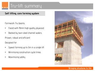
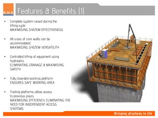
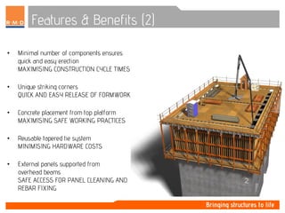
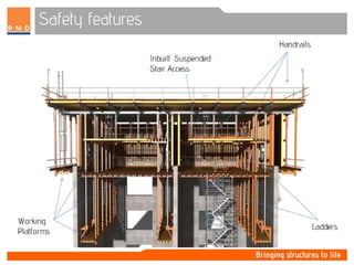
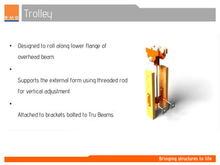
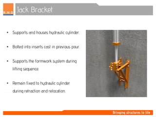
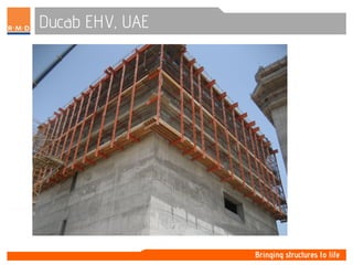
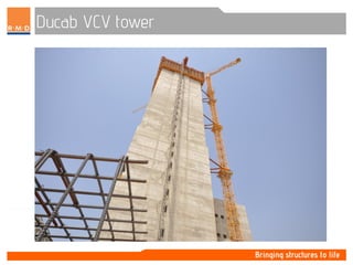
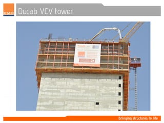
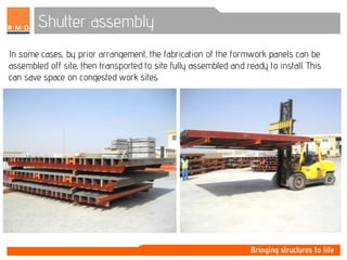
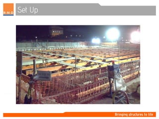
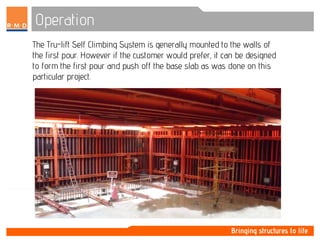
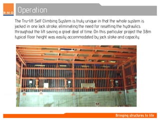
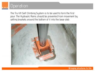
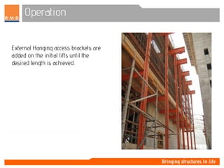
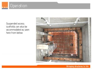
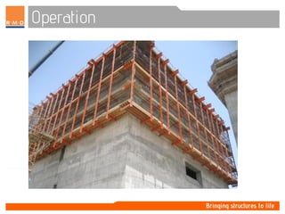
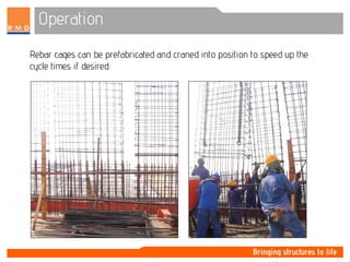
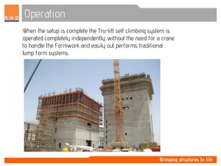
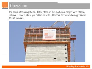
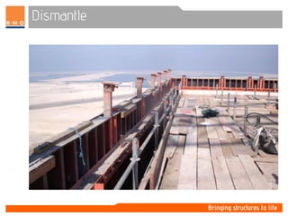
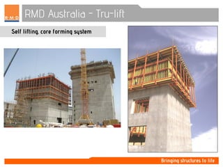
Tru-lift: summary
Self lifting, core forming system
Formwork: Tru beams
• Faced with 19mm high quality plywood
• Backed by twin steel channel walers
Proven, robust and efficient
Designed for:
• Speed: forming up to 5m in a single lift
• Minimising construction cycle times
• Maximising safety
System characteristics
• 4.1 m Stroke on long cylinder.
• 0.9m Stroke on small extension cylinder.
• Power supply 230v single phase 60 Hz.
• Maximum allowable working load on form support brackets = 155kN.
• Maximum allowable working load on cylinder brackets = 289kN.
• Taper Ties = 150kN (with FOS 2:1).
• Platform loading = 1.2kN/m2.
Features & Benefits (1)
• Complete system raised during the
lifting cycle
MAXIMISING SYSTEM EFFECTIVENESS
• All sizes of core walls can be
accommodated
MAXIMISING SYSTEM VERSATILITY
• Controlled lifting of equipment using
hydraulics
ELIMINATING CRANAGE & MAXIMISING
SAFETY
• Fully boarded working platform
ENSURES SAFE WORKING AREA
• Trailing platforms allow access
to previous pours
MAXIMISING EFFICIENCY, ELIMINATING THE
NEED FOR INDEPENDENT ACCESS
SYSTEMS
Features & Benefits (2)
• Minimal number of components ensures
quick and easy erection
MAXIMISING CONSTRUCTION CYCLE TIMES
• Unique striking corners
QUICK AND EASY RELEASE OF FORMWORK
• Concrete placement from top platform
MAXIMISING SAFE WORKING PRACTICES
• Reusable tapered tie system
MINIMISING HARDWARE COSTS
• External panels supported from
overhead beams
SAFE ACCESS FOR PANEL CLEANING AND
REBAR FIXING
Raised position
• Forms fully extended to
subsequent pour position.
• Wall support brackets bolted to
inserts cast in previous pour.
• Weight of system transferred to
wall support brackets.
Setting position
• Bolts securing cylinder brackets to wall
removed.
• Cylinder and bracket retracted and bolted to
inserts cast in previous pour.
• Internal forms cleaned and reset into
position.
• External forms cleaned whilst retracted.
Pouring position
• External forms rolled back into
pouring position.
• Ties and external yokes installed.
• Concrete placed through hinged
hatches on top platform.
Safety features
Safety: handrails
Full perimeter handrails for areas,
including:
• Upper platforms.
• Lower platforms.
• Internal hanging platforms.
Safety: Perimeter Screen
• Fully enclosed system.
• Welded loops for securing screen to
perimeter framework.
• Screen:
• Reinforced PVC sheeting.
• Strong and puncture resistant.
• UV stabilised.
• Fully printable.
• Ideal for advertising.
• Optional.
Safety: enclosed ladders
Full ladder access between platforms.
• Easy and safe accessibility at all times.
Safety: inbuilt stair access
• Modular stair access tower system.
• Supported off internal platforms.
• Length of tower determined by
floor level egress/ingress required.
• Optional.
Safety: Working Platforms
Safe, level working environment created
using timber beams and plywood.
• Minimises trip hazards.
• Fully covered work areas.
• Ply hatches for concrete placement.
Outer Corner Assembly
• External corners easily tied between
yoke blocks, using fast thread ties.
• Yoke blocks bolted to horizontal
channel walers.
Inner Corner Assembly
Corner pin used to strike internal forms:
• Drives through offset holes and reversed
for ‘reset’.
Trolley
• Designed to roll along lower flange of
overhead beam.
•
Supports the external form using threaded rod
for vertical adjustment.
•
Attached to brackets bolted to Tru Beams.
Internal form hanging bracket
• Adjustable form support bracket head
and clamp plates bolted into wall
support frame.
• Facilitates the connection to the
overhead primary beam.
Internal Corners
• Rigid, flexible and strippable corners
(depending on core profile).
• Where possible, flexible corners used in
conjunction with corner pins.
• Eliminates need to dismantle forms.
Wall Bracket Assembly
• Brackets bolted into inserts cast in
previous pour.
• Connected to wall support frame,
supporting formwork once in lifted
position.
• Finite adjustment for levelling using
Threaded Bar (if required).
Jack Bracket
• Supports and houses hydraulic cylinder.
• Bolted into inserts cast in previous pour.
• Supports the formwork system during
lifting sequence.
• Remain fixed to hydraulic cylinder
during retraction and relocation.
Walkway Bracket
• Bolted to overhead beam system.
• Hanging below the bottom of the
formwork system.
• Facilitates retracting of forms, steel
reinforcement fixing and cleaning of
forms.
• Designed to be used in conjunction with
timber beams and plywood.
• Creating a level and hazard free working
platform.
Internal Trailing Platform
• Supported from overhead steel beams.
• Provide safe access for operatives.
Ducab EHV, UAE
155m
Ducab EHV, UAE
340 N. LaSalle Chicago, IL.
60 Floors
J.W. Marriott Hotel Indianapolis, IN.
33 Floors
The Revel Atlantic City, N.J.
65 Floors
Queen City Square Cincinnati, OH.
47 Floors
Trump Tower Chicago, IL.
95 Floors
The Echelon Las Vegas, NV.
Ducab VCV tower, Dubai - UAE
Project: Ducab-HV (400kV) Cable Factory
- 1st Facility of it’s kind
- Fast Track (12 month program)
Sector: Industrial
Details: RC Tower
- 24 x 22m footprint
- 44 storey – 153m high
- Unique – large core structure, large
openings, changing wall thickness
Contractor: Khansaheb Civil Engineering
Ducab VCV tower
Ducab VCV tower
Shutter assembly
Pre-assembly of many components greatly reduces the
set up time onsite and can be started well in advance of
the site being ready to install the formwork.
Shutter assembly
Pre-assembly of the formwork is carried out using fabrication jigs and
can also be done well in advance of the actual site set up (on or off
site).
Shutter assembly
In some cases, by prior arrangement, the fabrication of the formwork panels can be
assembled off site, then transported to site fully assembled and ready to install. This
can save space on congested work sites.
Shutter assembly
Larger panels that are too big to be transported by road can be assembled
on site.
Set Up
The formwork panels are then prepared and oiled prior to lifting into
position.
Set Up
The Internal Rigid Boxes are installed first and fixes the internal
shape/dimensions of the core – this is a unique feature of the
Tru-lift Self Climbing Formwork System.
Set Up
The Steel Walers are easily spliced to any length enabling very large panels
such as this 4.2m high x 20m long panel to be fabricated and lifted into
position in one piece.
Set Up
Set Up
Set Up
On completion of the rebar and formwork installation the steel grid
beams are positioned.
Set Up
Set Up
Bolts and Grid Plates are used for the connections between the grid beams, the
Formwork and Hydraulics.
Set Up
Top Decking and Edge Protection are added upon completion of the Grid
Beam placement.
Operation
The Tru-lift Self Climbing System is operated from a central control
room. Each of the Hydraulic Rams can be controlled individually or
collectively with the flick of one switch.
Operation
The Tru-lift Self Climbing System is generally mounted to the walls of
the first pour. However if the customer would prefer, it can be designed
to form the first pour and push off the base slab as was done on this
particular project.
Operation
The Tru-lift Self Climbing System is truly unique in that the whole system is
jacked in one Jack stroke, eliminating the need for resetting the hydraulics
throughout the lift saving a great deal of time. On this particular project the 3.8m
typical floor height was easily accommodated by jack stoke and capacity.
Operation
The Tru-lift Self Climbing System is to be used to form the first
pour. The Hydraulic Rams should be prevented from movement by
setting brackets around the bottom of it into the base slab.
Operation
External Hanging access brackets are
added on the initial lifts until the
desired length is achieved.
Operation
Suspended access
scaffolds can also be
accommodated as seen
here from below.
Operation
Operation
Rebar cages can be prefabricated and craned into position to speed up the
cycle times if desired.
Operation
When the setup is complete the Tru-lift self climbing system is
operated completely independently, without the need for a crane
to handle the Formwork and easily out performs traditional
Jump form systems.
Operation
The contractor using the Tru-lift System on this particular project was able to
achieve a pour cycle of just 48 hours with 1,100m2 of formwork being jacked in
20-30 minutes.
Dismantle
Upon completion of the structure the system is dismantled in the reverse order to
that of the erection.
The Hanging access
platforms are
removed first.
Dismantle
Followed by the external formwork.
Dismantle
Next the top decking is systematically removed.
Dismantle
Dismantle
The final step is the removal of the internal formwork and wall brackets.
Methods
Detailed method statements are
provided for assembly, erection,
running and dismantle of the
system.
Site supervision is provided at all
stages of the contract.
RMD Australia - Tru-lift
Self lifting, core forming system

Trulift presentation

  • 1.
    Tru-lift: summary Self lifting,core forming system Formwork: Tru beams • Faced with 19mm high quality plywood • Backed by twin steel channel walers Proven, robust and efficient Designed for: • Speed: forming up to 5m in a single lift • Minimising construction cycle times • Maximising safety
  • 2.
    System characteristics • 4.1m Stroke on long cylinder. • 0.9m Stroke on small extension cylinder. • Power supply 230v single phase 60 Hz. • Maximum allowable working load on form support brackets = 155kN. • Maximum allowable working load on cylinder brackets = 289kN. • Taper Ties = 150kN (with FOS 2:1). • Platform loading = 1.2kN/m2.
  • 3.
    Features & Benefits(1) • Complete system raised during the lifting cycle MAXIMISING SYSTEM EFFECTIVENESS • All sizes of core walls can be accommodated MAXIMISING SYSTEM VERSATILITY • Controlled lifting of equipment using hydraulics ELIMINATING CRANAGE & MAXIMISING SAFETY • Fully boarded working platform ENSURES SAFE WORKING AREA • Trailing platforms allow access to previous pours MAXIMISING EFFICIENCY, ELIMINATING THE NEED FOR INDEPENDENT ACCESS SYSTEMS
  • 4.
    Features & Benefits(2) • Minimal number of components ensures quick and easy erection MAXIMISING CONSTRUCTION CYCLE TIMES • Unique striking corners QUICK AND EASY RELEASE OF FORMWORK • Concrete placement from top platform MAXIMISING SAFE WORKING PRACTICES • Reusable tapered tie system MINIMISING HARDWARE COSTS • External panels supported from overhead beams SAFE ACCESS FOR PANEL CLEANING AND REBAR FIXING
  • 5.
    Raised position • Formsfully extended to subsequent pour position. • Wall support brackets bolted to inserts cast in previous pour. • Weight of system transferred to wall support brackets.
  • 6.
    Setting position • Boltssecuring cylinder brackets to wall removed. • Cylinder and bracket retracted and bolted to inserts cast in previous pour. • Internal forms cleaned and reset into position. • External forms cleaned whilst retracted.
  • 7.
    Pouring position • Externalforms rolled back into pouring position. • Ties and external yokes installed. • Concrete placed through hinged hatches on top platform.
  • 8.
  • 9.
    Safety: handrails Full perimeterhandrails for areas, including: • Upper platforms. • Lower platforms. • Internal hanging platforms.
  • 10.
    Safety: Perimeter Screen •Fully enclosed system. • Welded loops for securing screen to perimeter framework. • Screen: • Reinforced PVC sheeting. • Strong and puncture resistant. • UV stabilised. • Fully printable. • Ideal for advertising. • Optional.
  • 11.
    Safety: enclosed ladders Fullladder access between platforms. • Easy and safe accessibility at all times.
  • 12.
    Safety: inbuilt stairaccess • Modular stair access tower system. • Supported off internal platforms. • Length of tower determined by floor level egress/ingress required. • Optional.
  • 13.
    Safety: Working Platforms Safe,level working environment created using timber beams and plywood. • Minimises trip hazards. • Fully covered work areas. • Ply hatches for concrete placement.
  • 14.
    Outer Corner Assembly •External corners easily tied between yoke blocks, using fast thread ties. • Yoke blocks bolted to horizontal channel walers.
  • 15.
    Inner Corner Assembly Cornerpin used to strike internal forms: • Drives through offset holes and reversed for ‘reset’.
  • 16.
    Trolley • Designed toroll along lower flange of overhead beam. • Supports the external form using threaded rod for vertical adjustment. • Attached to brackets bolted to Tru Beams.
  • 17.
    Internal form hangingbracket • Adjustable form support bracket head and clamp plates bolted into wall support frame. • Facilitates the connection to the overhead primary beam.
  • 18.
    Internal Corners • Rigid,flexible and strippable corners (depending on core profile). • Where possible, flexible corners used in conjunction with corner pins. • Eliminates need to dismantle forms.
  • 19.
    Wall Bracket Assembly •Brackets bolted into inserts cast in previous pour. • Connected to wall support frame, supporting formwork once in lifted position. • Finite adjustment for levelling using Threaded Bar (if required).
  • 20.
    Jack Bracket • Supportsand houses hydraulic cylinder. • Bolted into inserts cast in previous pour. • Supports the formwork system during lifting sequence. • Remain fixed to hydraulic cylinder during retraction and relocation.
  • 21.
    Walkway Bracket • Boltedto overhead beam system. • Hanging below the bottom of the formwork system. • Facilitates retracting of forms, steel reinforcement fixing and cleaning of forms. • Designed to be used in conjunction with timber beams and plywood. • Creating a level and hazard free working platform.
  • 22.
    Internal Trailing Platform •Supported from overhead steel beams. • Provide safe access for operatives.
  • 23.
  • 24.
  • 25.
    340 N. LaSalleChicago, IL. 60 Floors
  • 26.
    J.W. Marriott HotelIndianapolis, IN. 33 Floors
  • 27.
    The Revel AtlanticCity, N.J. 65 Floors
  • 28.
    Queen City SquareCincinnati, OH. 47 Floors
  • 29.
    Trump Tower Chicago,IL. 95 Floors
  • 30.
    The Echelon LasVegas, NV.
  • 31.
    Ducab VCV tower,Dubai - UAE Project: Ducab-HV (400kV) Cable Factory - 1st Facility of it’s kind - Fast Track (12 month program) Sector: Industrial Details: RC Tower - 24 x 22m footprint - 44 storey – 153m high - Unique – large core structure, large openings, changing wall thickness Contractor: Khansaheb Civil Engineering
  • 32.
  • 33.
  • 34.
    Shutter assembly Pre-assembly ofmany components greatly reduces the set up time onsite and can be started well in advance of the site being ready to install the formwork.
  • 35.
    Shutter assembly Pre-assembly ofthe formwork is carried out using fabrication jigs and can also be done well in advance of the actual site set up (on or off site).
  • 36.
    Shutter assembly In somecases, by prior arrangement, the fabrication of the formwork panels can be assembled off site, then transported to site fully assembled and ready to install. This can save space on congested work sites.
  • 37.
    Shutter assembly Larger panelsthat are too big to be transported by road can be assembled on site.
  • 38.
    Set Up The formworkpanels are then prepared and oiled prior to lifting into position.
  • 39.
    Set Up The InternalRigid Boxes are installed first and fixes the internal shape/dimensions of the core – this is a unique feature of the Tru-lift Self Climbing Formwork System.
  • 40.
    Set Up The SteelWalers are easily spliced to any length enabling very large panels such as this 4.2m high x 20m long panel to be fabricated and lifted into position in one piece.
  • 41.
  • 42.
  • 43.
    Set Up On completionof the rebar and formwork installation the steel grid beams are positioned.
  • 44.
  • 45.
    Set Up Bolts andGrid Plates are used for the connections between the grid beams, the Formwork and Hydraulics.
  • 46.
    Set Up Top Deckingand Edge Protection are added upon completion of the Grid Beam placement.
  • 47.
    Operation The Tru-lift SelfClimbing System is operated from a central control room. Each of the Hydraulic Rams can be controlled individually or collectively with the flick of one switch.
  • 48.
    Operation The Tru-lift SelfClimbing System is generally mounted to the walls of the first pour. However if the customer would prefer, it can be designed to form the first pour and push off the base slab as was done on this particular project.
  • 49.
    Operation The Tru-lift SelfClimbing System is truly unique in that the whole system is jacked in one Jack stroke, eliminating the need for resetting the hydraulics throughout the lift saving a great deal of time. On this particular project the 3.8m typical floor height was easily accommodated by jack stoke and capacity.
  • 50.
    Operation The Tru-lift SelfClimbing System is to be used to form the first pour. The Hydraulic Rams should be prevented from movement by setting brackets around the bottom of it into the base slab.
  • 51.
    Operation External Hanging accessbrackets are added on the initial lifts until the desired length is achieved.
  • 52.
    Operation Suspended access scaffolds canalso be accommodated as seen here from below.
  • 53.
  • 54.
    Operation Rebar cages canbe prefabricated and craned into position to speed up the cycle times if desired.
  • 55.
    Operation When the setupis complete the Tru-lift self climbing system is operated completely independently, without the need for a crane to handle the Formwork and easily out performs traditional Jump form systems.
  • 56.
    Operation The contractor usingthe Tru-lift System on this particular project was able to achieve a pour cycle of just 48 hours with 1,100m2 of formwork being jacked in 20-30 minutes.
  • 57.
    Dismantle Upon completion ofthe structure the system is dismantled in the reverse order to that of the erection. The Hanging access platforms are removed first.
  • 58.
    Dismantle Followed by theexternal formwork.
  • 59.
    Dismantle Next the topdecking is systematically removed.
  • 60.
  • 61.
    Dismantle The final stepis the removal of the internal formwork and wall brackets.
  • 62.
    Methods Detailed method statementsare provided for assembly, erection, running and dismantle of the system. Site supervision is provided at all stages of the contract.
  • 63.
    RMD Australia -Tru-lift Self lifting, core forming system