The document summarizes key aspects of transformers:
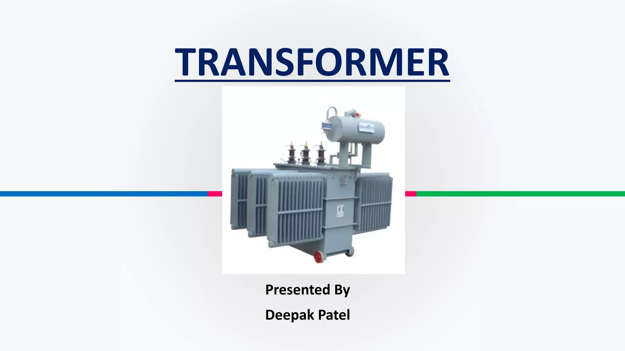
1. Transformers transfer electric power from one circuit to another through electromagnetic induction without changing frequency. They are used to step up or step down AC voltage for power transmission or distribution.
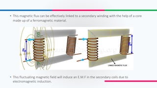
2. The working principle is based on electromagnetic induction - a changing magnetic field in the primary winding induces a voltage in the secondary winding.
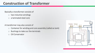
3. Main components are the primary and secondary windings wrapped around a laminated steel core to maximize the magnetic flux between coils.