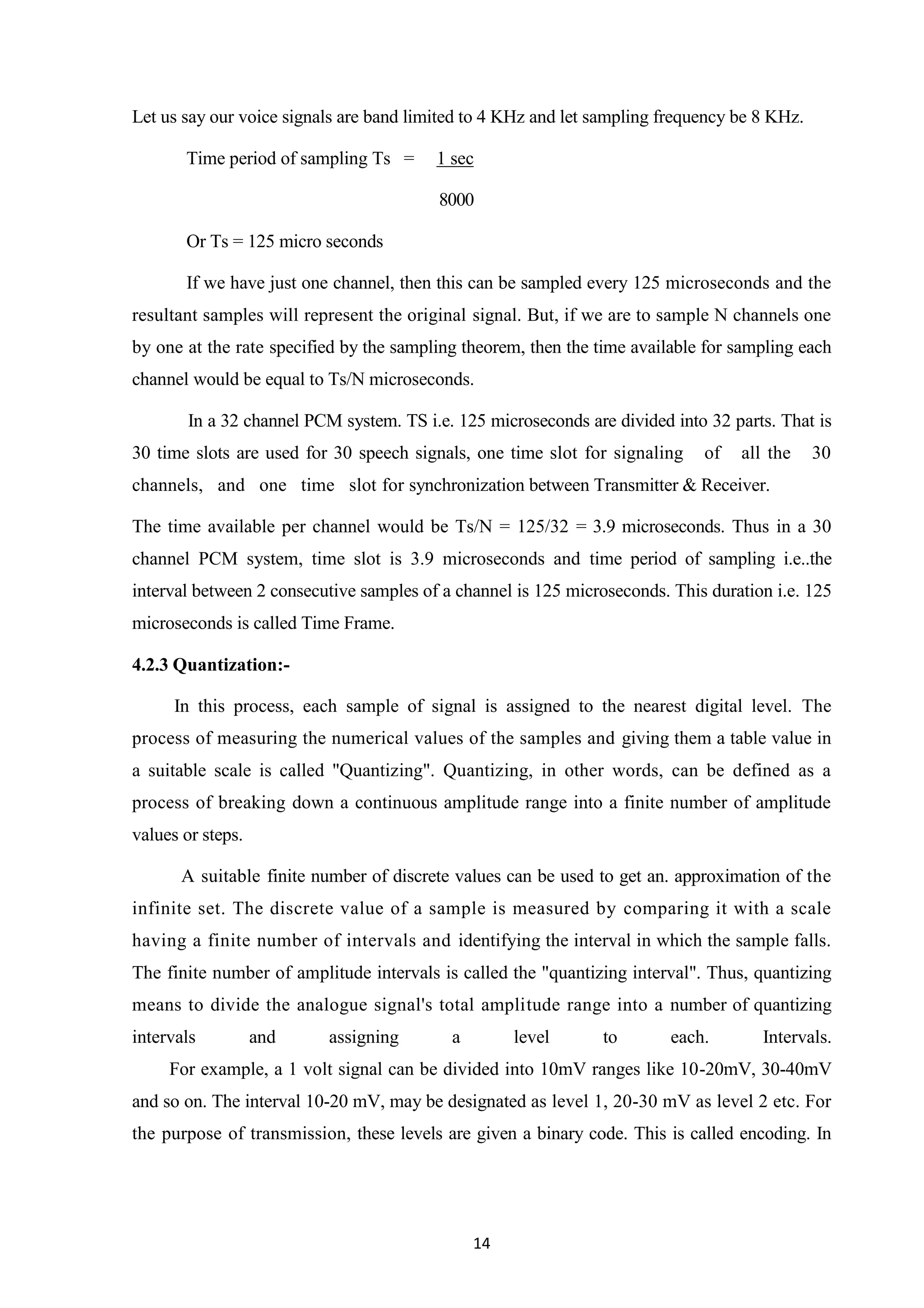
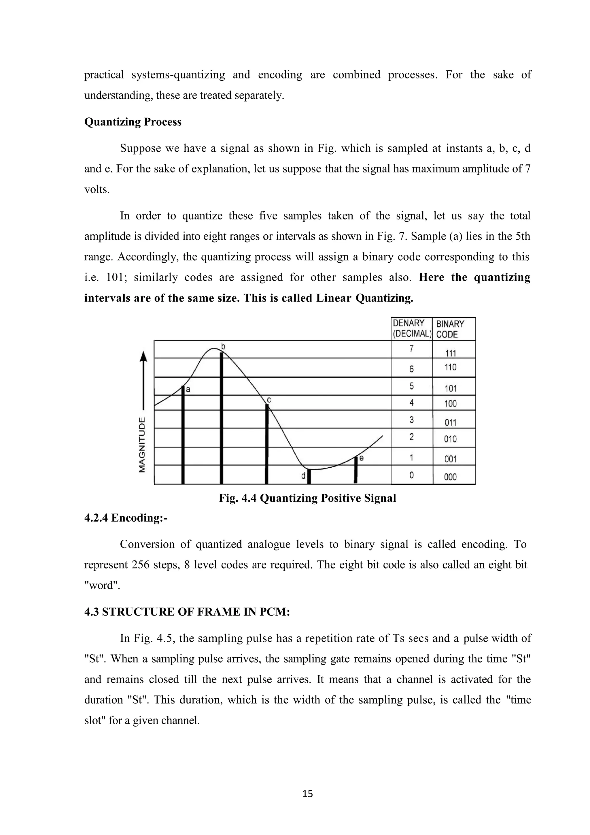
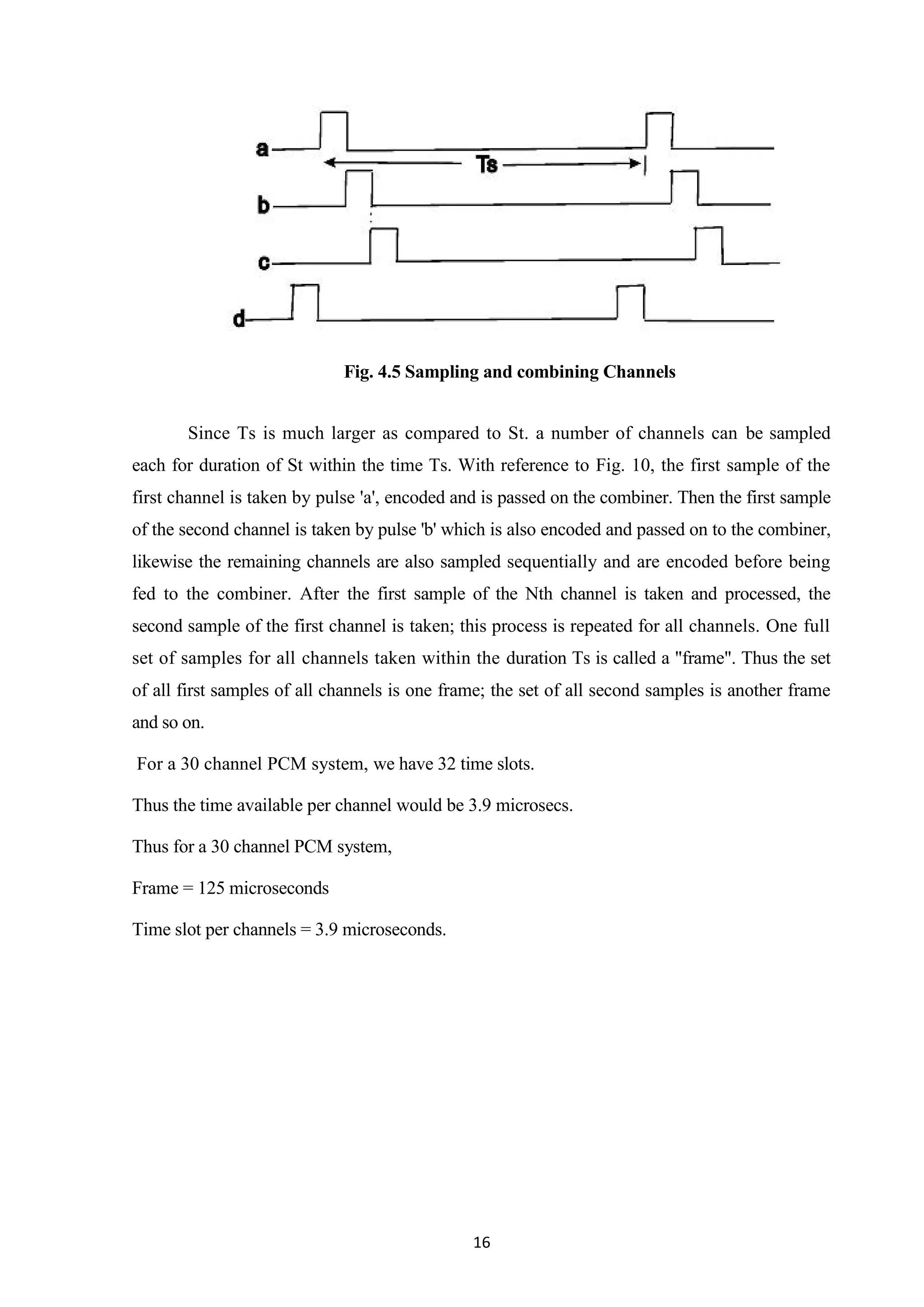
Downloaded 50 times


![iv
ACKNOWLEDGEMENT
It is with profound gratitude that I express my deep indebtedness to all the employees of
B.S.N.L. without whose support and guidance it would not have been possible for this
training to have materialized and taken a concrete shape.
I would like to make a number of acknowledgements to those who have helped me to
prepare this Seminar.
We are highly grateful to Prof. O. P. VYAS, Dean (Engineering), JIET for proving us
this opportunity to carry out independent study on this topic.
The divine support given by our guide MR.AJAY CHOUDHARY [SDE(INTERNAL)]
and Prof. K. K. ARORA, HOD(M. Tech) & Prof. (Dr.) HEMANT PUROHIT, HOD
(B. Tech) Department of Electronics and Communication Engineering, J.I.E.T, Jodhpur,
without them the work would not possible.
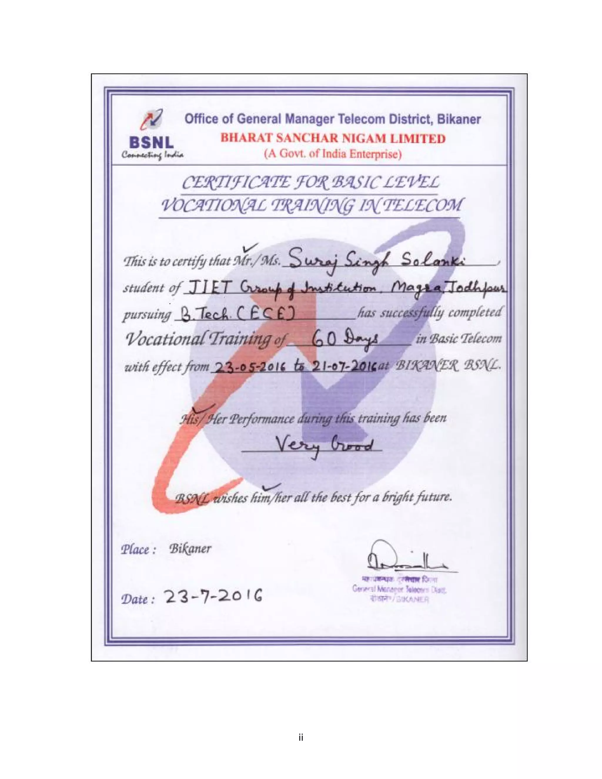
NAME
SURAJ SINGH SOLANKI
ROLL NO
13EJIEC105](https://image.slidesharecdn.com/trainingreportonbsnl-180519074804/75/Training-report-on-bsnl-4-2048.jpg)


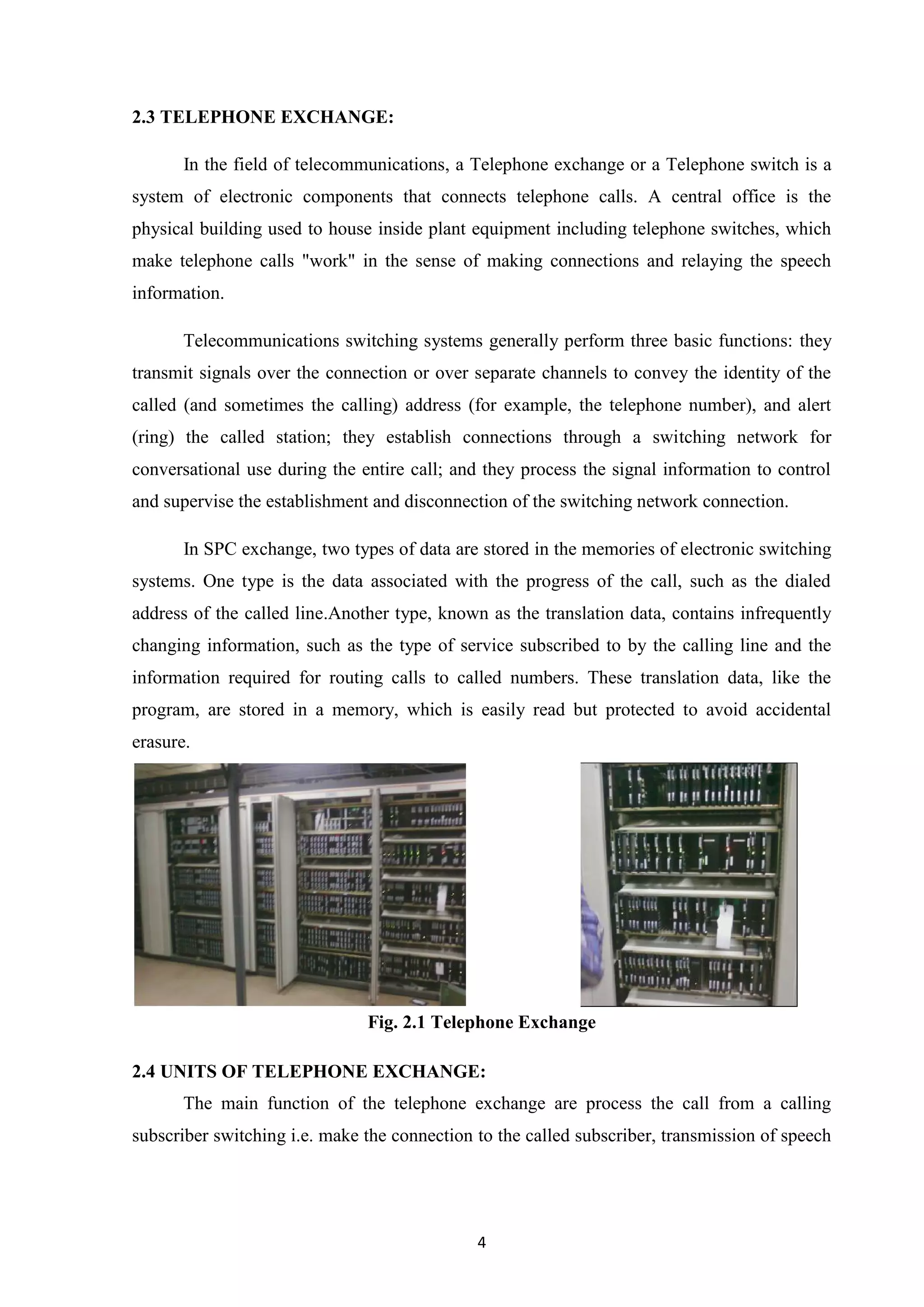


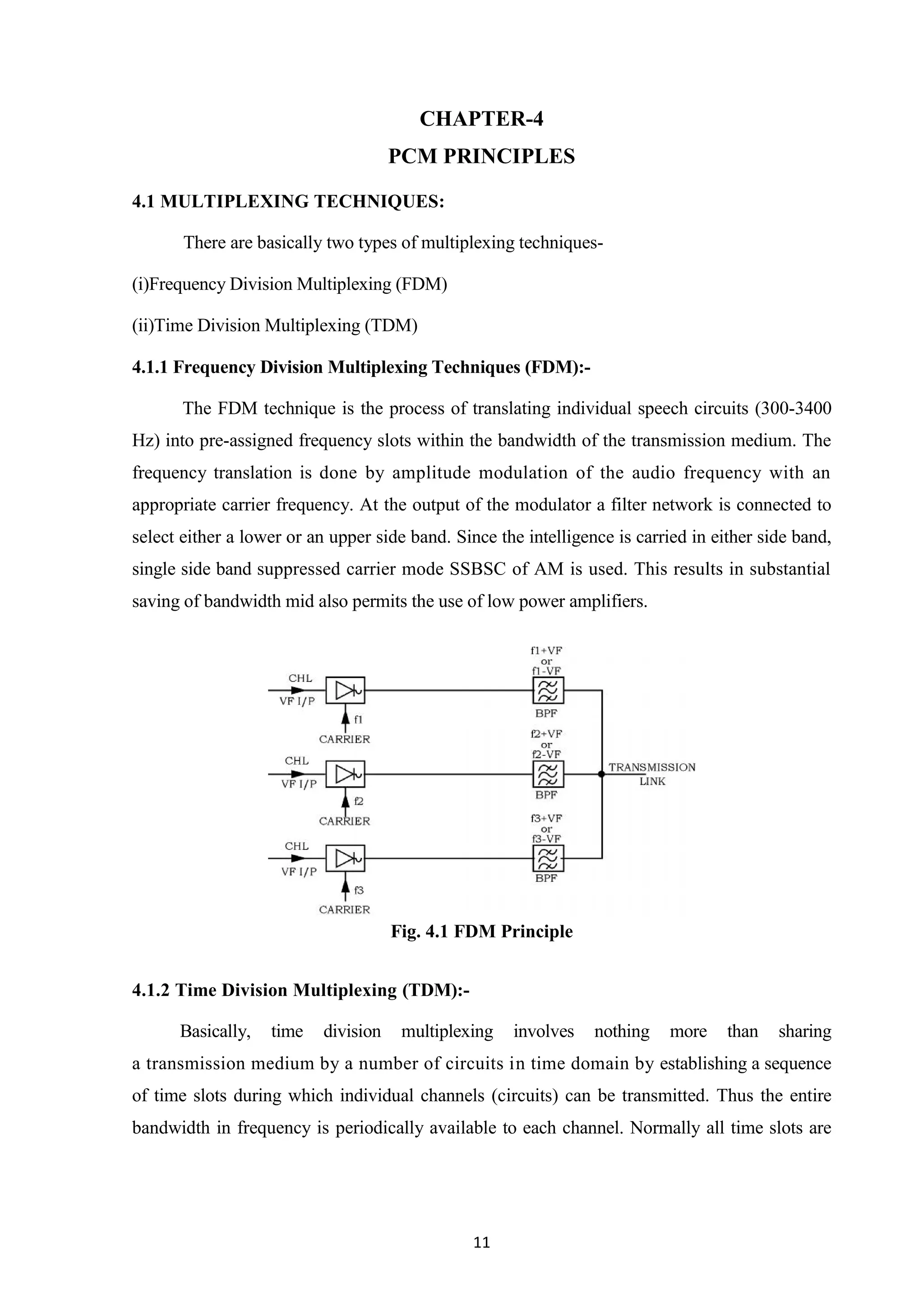
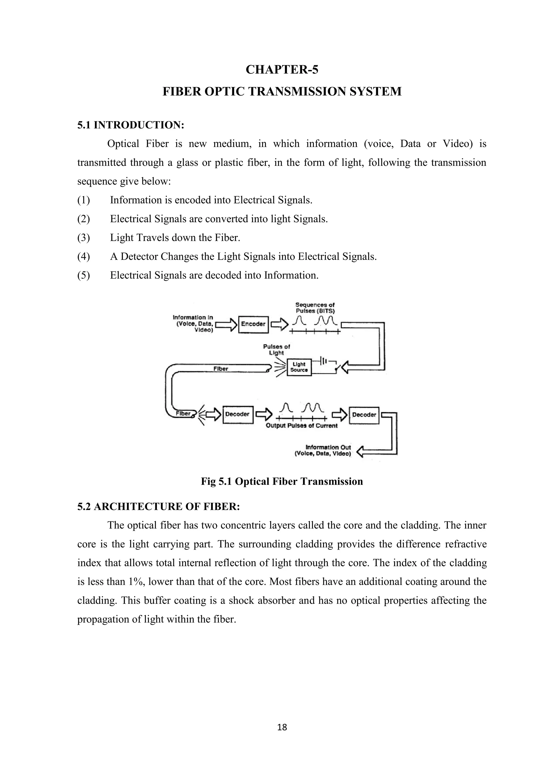


This report documents a practical training seminar at Bharat Sanchar Nigam Limited (BSNL) by Suraj Singh Solanki, covering various aspects of telecommunications including the company's structure, telephone exchanges, switching systems, and modern technologies like GSM and Wi-Fi over 10 chapters. The training aimed to provide hands-on experience to engineering students and emphasizes the rapid growth of the telecommunications industry. The report also acknowledges the guidance from faculty and contributions of BSNL employees to the practical training experience.