The document provides specifications and maintenance procedures for various motors used on Toyota vehicles. It includes sections on the drive motor, pump motor, and power steering motor. Removal and installation procedures are outlined along with disassembly, inspection, and reassembly steps. Key points are highlighted and lubrication requirements and torque specifications are provided. The document also includes an index and exterior views of vehicle models to help technicians service the appropriate components.
TOYOTA 7FBMF50 Forklift Service Repair Manualfujjdfjkksekmem
This is the Highly Detailed factory service repair manual for theTOYOTA 7FBMF50 FORKLIFT, this Service Manual has detailed illustrations as well as step by step instructions,It is 100 percents complete and intact. they are specifically written for the do-it-yourself-er as well as the experienced mechanic.TOYOTA 7FBMF50 FORKLIFT Service Repair Workshop Manual provides step-by-step instructions based on the complete dis-assembly of the machine. It is this level of detail, along with hundreds of photos and illustrations, that guide the reader through each service and repair procedure. Complete download comes in pdf format which can work under all PC based windows operating system and Mac also, All pages are printable. Using this repair manual is an inexpensive way to keep your vehicle working properly.
Service Repair Manual Covers:
General
Battery
Controller
Multi-Display Functions
Troubleshooting
Motor
Drive Unit
Front Axle
Rear Axle
Steering
Brake
Body
Material Handling System
Mast
Cylinder
Oil Pump
Oil Control Valve
SAS Functions
Appendix
File Format: PDF
Compatible: All Versions of Windows & Mac
Language: English
Requirements: Adobe PDF Reader
NO waiting, Buy from responsible seller and get INSTANT DOWNLOAD, Without wasting your hard-owned money on uncertainty or surprise! All pages are is great to haveTOYOTA 7FBMF50 FORKLIFT Service Repair Workshop Manual.
Thanks for visiting!
TOYOTA 7FBMF45 Forklift Service Repair Manualfujjdfjkksekmem
This is the Highly Detailed factory service repair manual for theTOYOTA 7FBMF45 FORKLIFT, this Service Manual has detailed illustrations as well as step by step instructions,It is 100 percents complete and intact. they are specifically written for the do-it-yourself-er as well as the experienced mechanic.TOYOTA 7FBMF45 FORKLIFT Service Repair Workshop Manual provides step-by-step instructions based on the complete dis-assembly of the machine. It is this level of detail, along with hundreds of photos and illustrations, that guide the reader through each service and repair procedure. Complete download comes in pdf format which can work under all PC based windows operating system and Mac also, All pages are printable. Using this repair manual is an inexpensive way to keep your vehicle working properly.
Service Repair Manual Covers:
General
Battery
Controller
Multi-Display Functions
Troubleshooting
Motor
Drive Unit
Front Axle
Rear Axle
Steering
Brake
Body
Material Handling System
Mast
Cylinder
Oil Pump
Oil Control Valve
SAS Functions
Appendix
File Format: PDF
Compatible: All Versions of Windows & Mac
Language: English
Requirements: Adobe PDF Reader
NO waiting, Buy from responsible seller and get INSTANT DOWNLOAD, Without wasting your hard-owned money on uncertainty or surprise! All pages are is great to haveTOYOTA 7FBMF45 FORKLIFT Service Repair Workshop Manual.
Thanks for visiting!
TOYOTA 7FBMF40 Forklift Service Repair Manualfujjdfjkksekmem
This is the Highly Detailed factory service repair manual for theTOYOTA 7FBMF40 FORKLIFT, this Service Manual has detailed illustrations as well as step by step instructions,It is 100 percents complete and intact. they are specifically written for the do-it-yourself-er as well as the experienced mechanic.TOYOTA 7FBMF40 FORKLIFT Service Repair Workshop Manual provides step-by-step instructions based on the complete dis-assembly of the machine. It is this level of detail, along with hundreds of photos and illustrations, that guide the reader through each service and repair procedure. Complete download comes in pdf format which can work under all PC based windows operating system and Mac also, All pages are printable. Using this repair manual is an inexpensive way to keep your vehicle working properly.
Service Repair Manual Covers:
General
Battery
Controller
Multi-Display Functions
Troubleshooting
Motor
Drive Unit
Front Axle
Rear Axle
Steering
Brake
Body
Material Handling System
Mast
Cylinder
Oil Pump
Oil Control Valve
SAS Functions
Appendix
File Format: PDF
Compatible: All Versions of Windows & Mac
Language: English
Requirements: Adobe PDF Reader
NO waiting, Buy from responsible seller and get INSTANT DOWNLOAD, Without wasting your hard-owned money on uncertainty or surprise! All pages are is great to haveTOYOTA 7FBMF40 FORKLIFT Service Repair Workshop Manual.
Thanks for visiting!
TOYOTA 7FBMF35 Forklift Service Repair Manualfujjdfjkksekmem
This is the Highly Detailed factory service repair manual for theTOYOTA 7FBMF35 FORKLIFT, this Service Manual has detailed illustrations as well as step by step instructions,It is 100 percents complete and intact. they are specifically written for the do-it-yourself-er as well as the experienced mechanic.TOYOTA 7FBMF35 FORKLIFT Service Repair Workshop Manual provides step-by-step instructions based on the complete dis-assembly of the machine. It is this level of detail, along with hundreds of photos and illustrations, that guide the reader through each service and repair procedure. Complete download comes in pdf format which can work under all PC based windows operating system and Mac also, All pages are printable. Using this repair manual is an inexpensive way to keep your vehicle working properly.
Service Repair Manual Covers:
General
Battery
Controller
Multi-Display Functions
Troubleshooting
Motor
Drive Unit
Front Axle
Rear Axle
Steering
Brake
Body
Material Handling System
Mast
Cylinder
Oil Pump
Oil Control Valve
SAS Functions
Appendix
File Format: PDF
Compatible: All Versions of Windows & Mac
Language: English
Requirements: Adobe PDF Reader
NO waiting, Buy from responsible seller and get INSTANT DOWNLOAD, Without wasting your hard-owned money on uncertainty or surprise! All pages are is great to haveTOYOTA 7FBMF35 FORKLIFT Service Repair Workshop Manual.
Thanks for visiting!
TOYOTA 7FBMF30 Forklift Service Repair Manualfujjdfjkksekmem
This is the Highly Detailed factory service repair manual for theTOYOTA 7FBMF30 FORKLIFT, this Service Manual has detailed illustrations as well as step by step instructions,It is 100 percents complete and intact. they are specifically written for the do-it-yourself-er as well as the experienced mechanic.TOYOTA 7FBMF30 FORKLIFT Service Repair Workshop Manual provides step-by-step instructions based on the complete dis-assembly of the machine. It is this level of detail, along with hundreds of photos and illustrations, that guide the reader through each service and repair procedure. Complete download comes in pdf format which can work under all PC based windows operating system and Mac also, All pages are printable. Using this repair manual is an inexpensive way to keep your vehicle working properly.
Service Repair Manual Covers:
General
Battery
Controller
Multi-Display Functions
Troubleshooting
Motor
Drive Unit
Front Axle
Rear Axle
Steering
Brake
Body
Material Handling System
Mast
Cylinder
Oil Pump
Oil Control Valve
SAS Functions
Appendix
File Format: PDF
Compatible: All Versions of Windows & Mac
Language: English
Requirements: Adobe PDF Reader
NO waiting, Buy from responsible seller and get INSTANT DOWNLOAD, Without wasting your hard-owned money on uncertainty or surprise! All pages are is great to haveTOYOTA 7FBMF30 FORKLIFT Service Repair Workshop Manual.
Thanks for visiting!
TOYOTA 7FBMF25 Forklift Service Repair Manualfujjdfjkksekmem
This is the Highly Detailed factory service repair manual for theTOYOTA 7FBMF25 FORKLIFT, this Service Manual has detailed illustrations as well as step by step instructions,It is 100 percents complete and intact. they are specifically written for the do-it-yourself-er as well as the experienced mechanic.TOYOTA 7FBMF25 FORKLIFT Service Repair Workshop Manual provides step-by-step instructions based on the complete dis-assembly of the machine. It is this level of detail, along with hundreds of photos and illustrations, that guide the reader through each service and repair procedure. Complete download comes in pdf format which can work under all PC based windows operating system and Mac also, All pages are printable. Using this repair manual is an inexpensive way to keep your vehicle working properly.
Service Repair Manual Covers:
General
Battery
Controller
Multi-Display Functions
Troubleshooting
Motor
Drive Unit
Front Axle
Rear Axle
Steering
Brake
Body
Material Handling System
Mast
Cylinder
Oil Pump
Oil Control Valve
SAS Functions
Appendix
File Format: PDF
Compatible: All Versions of Windows & Mac
Language: English
Requirements: Adobe PDF Reader
NO waiting, Buy from responsible seller and get INSTANT DOWNLOAD, Without wasting your hard-owned money on uncertainty or surprise! All pages are is great to haveTOYOTA 7FBMF25 FORKLIFT Service Repair Workshop Manual.
Thanks for visiting!
TOYOTA 7FBMF20 Forklift Service Repair Manualfujjdfjkksekmem
This is the Highly Detailed factory service repair manual for theTOYOTA 7FBMF20 FORKLIFT, this Service Manual has detailed illustrations as well as step by step instructions,It is 100 percents complete and intact. they are specifically written for the do-it-yourself-er as well as the experienced mechanic.TOYOTA 7FBMF20 FORKLIFT Service Repair Workshop Manual provides step-by-step instructions based on the complete dis-assembly of the machine. It is this level of detail, along with hundreds of photos and illustrations, that guide the reader through each service and repair procedure. Complete download comes in pdf format which can work under all PC based windows operating system and Mac also, All pages are printable. Using this repair manual is an inexpensive way to keep your vehicle working properly.
Service Repair Manual Covers:
General
Battery
Controller
Multi-Display Functions
Troubleshooting
Motor
Drive Unit
Front Axle
Rear Axle
Steering
Brake
Body
Material Handling System
Mast
Cylinder
Oil Pump
Oil Control Valve
SAS Functions
Appendix
File Format: PDF
Compatible: All Versions of Windows & Mac
Language: English
Requirements: Adobe PDF Reader
NO waiting, Buy from responsible seller and get INSTANT DOWNLOAD, Without wasting your hard-owned money on uncertainty or surprise! All pages are is great to haveTOYOTA 7FBMF20 FORKLIFT Service Repair Workshop Manual.
Thanks for visiting!
TOYOTA 7FBMF18 Forklift Service Repair Manualfujjdfjkksekmem
This is the Highly Detailed factory service repair manual for theTOYOTA 7FBMF18 FORKLIFT, this Service Manual has detailed illustrations as well as step by step instructions,It is 100 percents complete and intact. they are specifically written for the do-it-yourself-er as well as the experienced mechanic.TOYOTA 7FBMF18 FORKLIFT Service Repair Workshop Manual provides step-by-step instructions based on the complete dis-assembly of the machine. It is this level of detail, along with hundreds of photos and illustrations, that guide the reader through each service and repair procedure. Complete download comes in pdf format which can work under all PC based windows operating system and Mac also, All pages are printable. Using this repair manual is an inexpensive way to keep your vehicle working properly.
Service Repair Manual Covers:
General
Battery
Controller
Multi-Display Functions
Troubleshooting
Motor
Drive Unit
Front Axle
Rear Axle
Steering
Brake
Body
Material Handling System
Mast
Cylinder
Oil Pump
Oil Control Valve
SAS Functions
Appendix
File Format: PDF
Compatible: All Versions of Windows & Mac
Language: English
Requirements: Adobe PDF Reader
NO waiting, Buy from responsible seller and get INSTANT DOWNLOAD, Without wasting your hard-owned money on uncertainty or surprise! All pages are is great to haveTOYOTA 7FBMF18 FORKLIFT Service Repair Workshop Manual.
Thanks for visiting!
Core technology of Hyundai Motor Group's EV platform 'E-GMP'Hyundai Motor Group
What’s the force behind Hyundai Motor Group's EV performance and quality?
Maximized driving performance and quick charging time through high-density battery pack and fast charging technology and applicable to various vehicle types!
Discover more about Hyundai Motor Group’s EV platform ‘E-GMP’!
What Does the Active Steering Malfunction Warning Mean for Your BMWTanner Motors
Discover the reasons why your BMW’s Active Steering malfunction warning might come on. From electrical glitches to mechanical failures and software anomalies, addressing these promptly with professional inspection and maintenance ensures continued safety and performance on the road, maintaining the integrity of your driving experience.
What Does the PARKTRONIC Inoperative, See Owner's Manual Message Mean for You...Autohaus Service and Sales
Learn what "PARKTRONIC Inoperative, See Owner's Manual" means for your Mercedes-Benz. This message indicates a malfunction in the parking assistance system, potentially due to sensor issues or electrical faults. Prompt attention is crucial to ensure safety and functionality. Follow steps outlined for diagnosis and repair in the owner's manual.
Things to remember while upgrading the brakes of your carjennifermiller8137
Upgrading the brakes of your car? Keep these things in mind before doing so. Additionally, start using an OBD 2 GPS tracker so that you never miss a vehicle maintenance appointment. On top of this, a car GPS tracker will also let you master good driving habits that will let you increase the operational life of your car’s brakes.
5 Warning Signs Your BMW's Intelligent Battery Sensor Needs AttentionBertini's German Motors
IBS monitors and manages your BMW’s battery performance. If it malfunctions, you will have to deal with an array of electrical issues in your vehicle. Recognize warning signs like dimming headlights, frequent battery replacements, and electrical malfunctions to address potential IBS issues promptly.
In this presentation, we have discussed a very important feature of BMW X5 cars… the Comfort Access. Things that can significantly limit its functionality. And things that you can try to restore the functionality of such a convenient feature of your vehicle.
𝘼𝙣𝙩𝙞𝙦𝙪𝙚 𝙋𝙡𝙖𝙨𝙩𝙞𝙘 𝙏𝙧𝙖𝙙𝙚𝙧𝙨 𝙞𝙨 𝙫𝙚𝙧𝙮 𝙛𝙖𝙢𝙤𝙪𝙨 𝙛𝙤𝙧 𝙢𝙖𝙣𝙪𝙛𝙖𝙘𝙩𝙪𝙧𝙞𝙣𝙜 𝙩𝙝𝙚𝙞𝙧 𝙥𝙧𝙤𝙙𝙪𝙘𝙩𝙨. 𝙒𝙚 𝙝𝙖𝙫𝙚 𝙖𝙡𝙡 𝙩𝙝𝙚 𝙥𝙡𝙖𝙨𝙩𝙞𝙘 𝙜𝙧𝙖𝙣𝙪𝙡𝙚𝙨 𝙪𝙨𝙚𝙙 𝙞𝙣 𝙖𝙪𝙩𝙤𝙢𝙤𝙩𝙞𝙫𝙚 𝙖𝙣𝙙 𝙖𝙪𝙩𝙤 𝙥𝙖𝙧𝙩𝙨 𝙖𝙣𝙙 𝙖𝙡𝙡 𝙩𝙝𝙚 𝙛𝙖𝙢𝙤𝙪𝙨 𝙘𝙤𝙢𝙥𝙖𝙣𝙞𝙚𝙨 𝙗𝙪𝙮 𝙩𝙝𝙚 𝙜𝙧𝙖𝙣𝙪𝙡𝙚𝙨 𝙛𝙧𝙤𝙢 𝙪𝙨.
Over the 10 years, we have gained a strong foothold in the market due to our range's high quality, competitive prices, and time-lined delivery schedules.
Comprehensive program for Agricultural Finance, the Automotive Sector, and Empowerment . We will define the full scope and provide a detailed two-week plan for identifying strategic partners in each area within Limpopo, including target areas.:
1. Agricultural : Supporting Primary and Secondary Agriculture
• Scope: Provide support solutions to enhance agricultural productivity and sustainability.
• Target Areas: Polokwane, Tzaneen, Thohoyandou, Makhado, and Giyani.
2. Automotive Sector: Partnerships with Mechanics and Panel Beater Shops
• Scope: Develop collaborations with automotive service providers to improve service quality and business operations.
• Target Areas: Polokwane, Lephalale, Mokopane, Phalaborwa, and Bela-Bela.
3. Empowerment : Focusing on Women Empowerment
• Scope: Provide business support support and training to women-owned businesses, promoting economic inclusion.
• Target Areas: Polokwane, Thohoyandou, Musina, Burgersfort, and Louis Trichardt.
We will also prioritize Industrial Economic Zone areas and their priorities.
Sign up on https://profilesmes.online/welcome/
To be eligible:
1. You must have a registered business and operate in Limpopo
2. Generate revenue
3. Sectors : Agriculture ( primary and secondary) and Automative
Women and Youth are encouraged to apply even if you don't fall in those sectors.
Symptoms like intermittent starting and key recognition errors signal potential problems with your Mercedes’ EIS. Use diagnostic steps like error code checks and spare key tests. Professional diagnosis and solutions like EIS replacement ensure safe driving. Consult a qualified technician for accurate diagnosis and repair.
What Exactly Is The Common Rail Direct Injection System & How Does It WorkMotor Cars International
Learn about Common Rail Direct Injection (CRDi) - the revolutionary technology that has made diesel engines more efficient. Explore its workings, advantages like enhanced fuel efficiency and increased power output, along with drawbacks such as complexity and higher initial cost. Compare CRDi with traditional diesel engines and discover why it's the preferred choice for modern engines.
"Trans Failsafe Prog" on your BMW X5 indicates potential transmission issues requiring immediate action. This safety feature activates in response to abnormalities like low fluid levels, leaks, faulty sensors, electrical or mechanical failures, and overheating.
Why Is Your BMW X3 Hood Not Responding To Release CommandsDart Auto
Experiencing difficulty opening your BMW X3's hood? This guide explores potential issues like mechanical obstruction, hood release mechanism failure, electrical problems, and emergency release malfunctions. Troubleshooting tips include basic checks, clearing obstructions, applying pressure, and using the emergency release.
Why Is Your BMW X3 Hood Not Responding To Release Commands
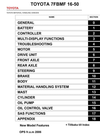
TOYOTA 7FBMF16 Forklift Service Repair Manual
1. SECTION INDEX
NAME SECTION
GENERAL 0
BATTERY 1
CONTROLLER 2
MULTI-DISPLAY FUNCTIONS 3
TROUBLESHOOTING 4
MOTOR 5
DRIVE UNIT 6
FRONT AXLE 7
REAR AXLE 8
STEERING 9
BRAKE 10
BODY 11
MATERIAL HANDLING SYSTEM 12
MAST 13
CYLINDER 14
OIL PUMP 15
OIL CONTROL VALVE 16
SAS FUNCTIONS 17
APPENDIX 18
TOYOTA 7FBMF 16-50
< Tillbaka till Index
New Model Features
OPS fr.o.m 2006
2. 0-1
0
1
2
3
4
5
6
7
8
9
10
11
12
13
14
15
16
17
18
19
20
21
22
GENERAL
Page
EXTERIOR VIEWS........................... 0-2
VEHICLE MODELS.......................... 0-4
FRAME NUMBER............................. 0-4
HOW TO USE THIS
MANUAL .......................................... 0-5
EXPLANATION METHOD ................. 0-5
TERMINOLOGY................................. 0-6
ABBREVIATIONS.............................. 0-6
OPERATIONAL TIPS ...................... 0-7
JACK-UP POINT .............................. 0-8
HOISTING THE VEHICLE.............. 0-9
CAUTION FOR TOWING................ 0-9
PARKING BRAKE RELEASE
METHOD.......................................... 0-9
ATTENTIVE POINTS ON SAS.... 0-10
CIRCUIT TESTER .......................... 0-11
STANDARD BOLT & NUT
TIGHTENING TORQUE.............. 0-13
BOLT STRENGTH TYPE
IDENTIFICATION METHOD.......... 0-13
TIGHTENING TORQUE TABLE...... 0-14
PRECOATED BOLTS ................... 0-15
HIGH PRESSURE HOSE
FITTING TIGHTENING
TORQUE......................................... 0-15
WIRE ROPE SUSPENSION
ANGLE LIST.................................. 0-16
Page
SAFE LOAD FOR EACH WIRE
ROPE SUSPENSION
ANGLE............................................ 0-16
COMPONENTS WEIGHT ............. 0-17
RECOMMENDED LUBRICANT
QUANTITY & TYPES .................. 0-18
LUBRICATION CHART ................ 0-19
PERIODIC MAINTENANCE......... 0-21
PERIODIC REPLACEMENT
OF PARTS AND
LUBRICANTS ............................... 0-25
Totaldokument, service...........0-26
5. 0-4
VEHICLE MODELS
FRAME NUMBER
Model code Load capacity Vehicle model Voltage
16 1.6 ton 7FBMF16 80 V/72 V
18 1.8 ton 7FBMF18 ↑
20 2.0 ton 7FBMF20 ↑
25 2.5 ton 7FBMF25 ↑
30 3.0 ton 7FBMF30 ↑
35 3.5 ton 7FBMF35 ↑
40 4.0 ton 7FBMF40 ↑
45 4.5 ton 7FBMF45 ↑
50 5.0 ton 7FBMF50 ↑
Vehicle model Punching format Frame No. punching position
)%0)
)%0)
)%0)
)%0)
)%0)
)%0)
)%0)
)%0)
)%0)
)%0)
)%0)
)%0)
)%0)
Punching position
6. 0-5
HOW TO USE THIS MANUAL
EXPLANATION METHOD
1. Operation procedure
(1) The operation procedure is described in either pattern A or pattern B below.
Pattern A:Explanation of each operation step with illustration.
Pattern B:Explanation of operation procedure by indicating step numbers in one illustration,
followed by explanation of cautions and notes summarized as point operations.
Example of description in pattern B
DISASSEMBLY INSPECTION REASSEMBLY
Tightening torque unit T = N⋅m (kgf⋅cm) [ft⋅lbf]
• •
Disassembly Procedure
1 Remove the cover. [Point 1]
2 Remove the bushing [Point 2] Operation explained later
3 Remove the gear.
Point Operations Explanation of key point for operation with an illustration
[Point 1]
Disassembly:
Put a match mark when removing the pump cover.
[Point 2]
Inspection:
Measure the bushing inside diameter.
Limit: 19.12 mm (0.7528 in)
T = 46.1 ~ 48.1
(470 ~ 490)
[34.0 ~ 35.5]
• Step Nos. are sometimes partially
omitted in illustrations.
• When a part requiring tightening
torque instruction is not indicated
in the illustration, the part name is
described in the illustration frame.
0
1
2
3
4
5
6
7
8
9
10
11
12
13
14
15
16
17
18
19
20
21
22
7. 0-6
2. How to read components figures (Example)
3. Matters omitted in this manual
(1) This manual omits description of the following jobs, but they should be performed in the actual
operation:
(a) Cleaning and washing of removed parts as required
(b) Visual inspection (partially described)
TERMINOLOGY
Caution:
Important matters of which negligence may cause hazards to the human body. Be sure to observe
them.
Note:
Important items of which negligence may cause breakage or breakdown, or matters in operation
procedure requiring special attention.
Standard: Values showing the allowable range for inspections and adjustments.
Limit: Maximum or minimum allowable value for inspections or adjustments.
ABBREVIATIONS
Abbreviation (code) Meaning Abbreviation (code) Meaning
ASSY Assembly SAE
Society of Automotive
Engineers (USA)
ATT Attachment SAS System of active stability
CHPS
Central hydraulic
power steering
SST Special service tool
LH Left hand STD Standard
L/ Less T = Tightening torque
OPT Option T Number of teeth ()
O/S Oversize U/S Undersize
PS Power steering W/ With
RH Right hand
3201
FIG number in parts catalog
(1) The components figure uses the illustration
in the parts catalog for the vehicle model.
Please refer to the catalog to check the part
name.
The number at the top right of each
components figure indicates the Fig.
number in the parts catalog.
11. 5-4
REMOVAL INSTALLATION
T = N·m (kgf·cm) [ft·lbf]
Removal Procedure
1 Remove the drive unit drive motor W/front axle ASSY. (See page 6-6.)
2 Remove the drive motor sensor bracket, terminal bracket, and sensor cover.
3 Place match marks between the end bracket, stator ASSY, and gear case.
4 Remove the nuts and through bolts. [Point 1]
5 Remove the end bracket. [Point 2]
6 Remove the stator ASSY W/rotor ASSY.
Installation Procedure
The installation procedure is the reverse of the removal procedure.
Note:
Apply MP grease to the rotor ASSY spline.
•
4
2
5
2 6
T = 45.0 ~ 55.0 (460 ~ 560)
[33.3 ~ 40.5]
12. 5-5
Point Operations
[Point 1]
Removal:
After removing the through bolts, use a hoist to lift the yoke
ASSY.
Installation:
After tightening the through bolts until they touch bottom,
tighten the nuts in the order shown in the figure.
Installation:
When replacing the motor with a new one, be sure to re-
move the stopper bolt and spacer installed in the center of
the end bracket. (They are not installed hereafter.)
[Point 2]
Removal:
Use a plastic hammer to tap lightly on the end bracket to
remove it.
Installation:
Use a plastic hammer to tap lightly on the end bracket to
install it.
Installation:
Align the speed sensor harness with the notch in the end
bracket and install the end bracket.
When doing this, do not forget to install the wave washer.
2
4
1
3
Spacer
Stopper bolt
Wave
washer
0
1
2
3
4
5
6
7
8
9
10
11
12
13
14
15
16
17
18
19
20
21
22
13. OBS! Lager finns som separat reservdel. P/N på sensorlagret:
5-6
DISASSEMBLY INSPECTION REASSEMBLY
Note:
• Do not apply a shock to the bearing W/speed sensor.
Disassembly Procedure
1 Remove the rotor ASSY W/bearing. [Point 1]
2 Remove the bearing. [Point 2]
Reassembly Procedure
The reassembly procedure is the reverse of the disassembly procedure.
• •
2
2
1
7FBMF 16-35 = 14160-F9802-71
7FBMF 40-50 = 14160-F9801-71
14. 5-7
Point Operations
[Point 1]
Inspection:
Measure the stator ASSY insulation resistance.
Measurement locations: Between the stator and each ter-
minal (U, V, W)
Standard: 1 MΩ or more
Inspection:
Measure the speed sensor insulation resistance.
Measurement locations: Between the stator and the speed
sensor connector terminals (4 locations)
Standard: ∞ Ω
Inspection:
Measure the temperature sensor insulation resistance.
Measurement locations: Between the stator and the tem-
perature sensor connector terminals (2 locations).
Standard: ∞ Ω
Measurement locations: Between the temperature sensor
connector terminals
Standard: 0.5 ~ 1.0 kΩ
[Point 2]
Disassembly:
SST 09950-76014-71
(SST 09950-40011)
SST
15. 5-8
Reassembly:
Use the following procedure to install the bearing.
1. Install the bearing (L/speed sensor).
SST 09370-20270-71
2. Install the bearing (W/speed sensor).
Tapping on the bearing could damage the sensor. Use
a press to install the bearing.
SST 09411-41800-71
SST
L/speed sensor
SST
W/speed sensor
19. 5-12
REMOVAL INSTALLATION
T = N·m (kgf·cm) [ft·lbf]
16 ~ 35 model
40 ~ 50 model
•
T = 16.2 ~ 37.8
(165 ~ 385)
[11.9 ~ 27.9]
8 T = 39.0 ~ 91.0
(398 ~ 928)
[28.8 ~ 67.1]
8
T = 16.2 ~ 37.8
(165 ~ 385)
[11.9 ~ 27.9]
8 T = 39.0 ~ 91.0
(398 ~ 928)
[28.8 ~ 67.1]
8
9
9
20. Thank you very much for
your reading. Please Click
Here. Then Get COMPLETE
MANUAL. NO WAITING
NOTE:
If there is no response to
click on the link above,
please download the PDF
document first and then
click on it.
21. 5-13
Removal Procedure
1 Remove the battery. (See page 13-10.)
2 Remove the counterweight. (See page 11-10.)
3 Remove the motor cable.
4 Disconnect the speed sensor and temperature sensor connectors.
5 Remove the oil pump set bolts and separate the oil pump from the pump motor.
6 Disconnect the swing lock solenoid connector.
7 Remove the lock cylinder cover.
8 Remove the lock cylinder lower pin and slide the swing lock cylinder to the left. [Point 1]
9 Remove the pump motor. [Point 2]
Installation Procedure
The installation procedure is the reverse of the removal procedure.
Note:
Apply lock agent (08833-76001-71 (08833-00070)) to the threads of the lock cylinder lower pin set
bolt and tighten the bolt.
Point Operations
[Point 1]
Removal•
Installation:
Jack up the rear axle and support the frame on wooden
blocks.
[Point 2] (40 ~ 50 model)
Removal•
Installation:
To prevent the right rear insulator bolt from being dam-
aged, connect shackles to the two left side wire ropes, and
then tilt and raise up the pump motor.
Installation:
Apply lock agent (08833-76002-71 (08833-00080)) to the
threads of the right rear insulator bolts and tighten the
bolts.
Apply lock
agent here
22. 5-14
DISASSEMBLY INSPECTION REASSEMBLY
Note:
• Do not apply a shock to the bearing W/speed sensor.
• The minimum unit of the parts supply for the bearing consists of “Rotor ASSY W/bearing” even
though the bearing is seperable on actual service.
T = N·m (kgf·cm) [ft·lbf]
Disassembly Procedure
1 Remove the end bracket (terminal side). [Point 1]
2 Remove the rotor ASSY W/bearing. [Point 2]
3 Remove the bearing. [Point 3]
4 Remove the stator ASSY. [Point 4]
Reassembly Procedure
The reassembly procedure is the reverse of the disassembly procedure.
• •
1
2
3
3
16 ~ 35 model:
T = 22.5 ~ 27.5 (229 ~ 280)
[16.6 ~ 20.3]
4
40 ~ 50 model:
T = 45 ~ 55 (459 ~ 561)
[33.2 ~ 40.6]
23. 5-15
Point Operations
[Point 1]
Disassembly:
Put match marks between the end bracket, stator ASSY,
and end bracket (terminal side).
Reassembly:
Align the match marks when installing.
Reassembly:
Align the speed sensor harness with the slot in the end
bracket (terminal side) and install the end bracket.
[Point 2]
Inspection:
Measure the speed sensor insulation resistance.
Measurement locations: Between the stator and the speed
sensor connector terminals (4 locations).
Standard: ∞ Ω
[Point 3]
Disassembly:
SST 09950-76014-71 ............(1)
(SST 09950-40011)
SST 09950-76018-71 ............(2)
(SST 09950-60010)
Reassembly:
Use the following procedure to install the bearing.
1. Install the bearing (L/speed sensor).
SST 09370-20270-71
Match marks
SST (1)
SST (2)
SST
L/speed sensor