Ever been troubled by the blinking sign and didn’t know what to do?
Here’s a handy guide to dashboard symbols so that you’ll never be confused again!
Save them for later and save the trouble!
Core technology of Hyundai Motor Group's EV platform 'E-GMP'Hyundai Motor Group
What’s the force behind Hyundai Motor Group's EV performance and quality?
Maximized driving performance and quick charging time through high-density battery pack and fast charging technology and applicable to various vehicle types!
Discover more about Hyundai Motor Group’s EV platform ‘E-GMP’!
What Exactly Is The Common Rail Direct Injection System & How Does It WorkMotor Cars International
Learn about Common Rail Direct Injection (CRDi) - the revolutionary technology that has made diesel engines more efficient. Explore its workings, advantages like enhanced fuel efficiency and increased power output, along with drawbacks such as complexity and higher initial cost. Compare CRDi with traditional diesel engines and discover why it's the preferred choice for modern engines.
Comprehensive program for Agricultural Finance, the Automotive Sector, and Empowerment . We will define the full scope and provide a detailed two-week plan for identifying strategic partners in each area within Limpopo, including target areas.:
1. Agricultural : Supporting Primary and Secondary Agriculture
• Scope: Provide support solutions to enhance agricultural productivity and sustainability.
• Target Areas: Polokwane, Tzaneen, Thohoyandou, Makhado, and Giyani.
2. Automotive Sector: Partnerships with Mechanics and Panel Beater Shops
• Scope: Develop collaborations with automotive service providers to improve service quality and business operations.
• Target Areas: Polokwane, Lephalale, Mokopane, Phalaborwa, and Bela-Bela.
3. Empowerment : Focusing on Women Empowerment
• Scope: Provide business support support and training to women-owned businesses, promoting economic inclusion.
• Target Areas: Polokwane, Thohoyandou, Musina, Burgersfort, and Louis Trichardt.
We will also prioritize Industrial Economic Zone areas and their priorities.
Sign up on https://profilesmes.online/welcome/
To be eligible:
1. You must have a registered business and operate in Limpopo
2. Generate revenue
3. Sectors : Agriculture ( primary and secondary) and Automative
Women and Youth are encouraged to apply even if you don't fall in those sectors.
Things to remember while upgrading the brakes of your carjennifermiller8137
Upgrading the brakes of your car? Keep these things in mind before doing so. Additionally, start using an OBD 2 GPS tracker so that you never miss a vehicle maintenance appointment. On top of this, a car GPS tracker will also let you master good driving habits that will let you increase the operational life of your car’s brakes.
In this presentation, we have discussed a very important feature of BMW X5 cars… the Comfort Access. Things that can significantly limit its functionality. And things that you can try to restore the functionality of such a convenient feature of your vehicle.
What Does the PARKTRONIC Inoperative, See Owner's Manual Message Mean for You...Autohaus Service and Sales
Learn what "PARKTRONIC Inoperative, See Owner's Manual" means for your Mercedes-Benz. This message indicates a malfunction in the parking assistance system, potentially due to sensor issues or electrical faults. Prompt attention is crucial to ensure safety and functionality. Follow steps outlined for diagnosis and repair in the owner's manual.
𝘼𝙣𝙩𝙞𝙦𝙪𝙚 𝙋𝙡𝙖𝙨𝙩𝙞𝙘 𝙏𝙧𝙖𝙙𝙚𝙧𝙨 𝙞𝙨 𝙫𝙚𝙧𝙮 𝙛𝙖𝙢𝙤𝙪𝙨 𝙛𝙤𝙧 𝙢𝙖𝙣𝙪𝙛𝙖𝙘𝙩𝙪𝙧𝙞𝙣𝙜 𝙩𝙝𝙚𝙞𝙧 𝙥𝙧𝙤𝙙𝙪𝙘𝙩𝙨. 𝙒𝙚 𝙝𝙖𝙫𝙚 𝙖𝙡𝙡 𝙩𝙝𝙚 𝙥𝙡𝙖𝙨𝙩𝙞𝙘 𝙜𝙧𝙖𝙣𝙪𝙡𝙚𝙨 𝙪𝙨𝙚𝙙 𝙞𝙣 𝙖𝙪𝙩𝙤𝙢𝙤𝙩𝙞𝙫𝙚 𝙖𝙣𝙙 𝙖𝙪𝙩𝙤 𝙥𝙖𝙧𝙩𝙨 𝙖𝙣𝙙 𝙖𝙡𝙡 𝙩𝙝𝙚 𝙛𝙖𝙢𝙤𝙪𝙨 𝙘𝙤𝙢𝙥𝙖𝙣𝙞𝙚𝙨 𝙗𝙪𝙮 𝙩𝙝𝙚 𝙜𝙧𝙖𝙣𝙪𝙡𝙚𝙨 𝙛𝙧𝙤𝙢 𝙪𝙨.
Over the 10 years, we have gained a strong foothold in the market due to our range's high quality, competitive prices, and time-lined delivery schedules.
"Trans Failsafe Prog" on your BMW X5 indicates potential transmission issues requiring immediate action. This safety feature activates in response to abnormalities like low fluid levels, leaks, faulty sensors, electrical or mechanical failures, and overheating.
Why Is Your BMW X3 Hood Not Responding To Release CommandsDart Auto
Experiencing difficulty opening your BMW X3's hood? This guide explores potential issues like mechanical obstruction, hood release mechanism failure, electrical problems, and emergency release malfunctions. Troubleshooting tips include basic checks, clearing obstructions, applying pressure, and using the emergency release.
5 Warning Signs Your BMW's Intelligent Battery Sensor Needs AttentionBertini's German Motors
IBS monitors and manages your BMW’s battery performance. If it malfunctions, you will have to deal with an array of electrical issues in your vehicle. Recognize warning signs like dimming headlights, frequent battery replacements, and electrical malfunctions to address potential IBS issues promptly.
Symptoms like intermittent starting and key recognition errors signal potential problems with your Mercedes’ EIS. Use diagnostic steps like error code checks and spare key tests. Professional diagnosis and solutions like EIS replacement ensure safe driving. Consult a qualified technician for accurate diagnosis and repair.
Wondering if Your Mercedes EIS is at Fault Here’s How to Tell
Toyota 02 7 fgf30 forklift service repair manual
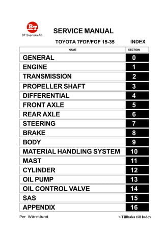
1. SERVICE MANUAL
TOYOTA 7FDF/FGF 15-35
BT Svenska AB
Per WärmlundPer WärmlundPer WärmlundPer WärmlundPer Wärmlund
NAME SECTION
GENERAL
ENGINE
TRANSMISSION
0
1
2
PROPELLER SHAFT
DIFFERENTIAL
FRONT AXLE
REAR AXLE
STEERING
BRAKE
BODY
MATERIAL HANDLING SYSTEM
MAST
CYLINDER
OIL PUMP
OIL CONTROL VALVE
SAS
APPENDIX
3
4
5
6
7
8
9
10
11
12
13
14
15
16
INDEX
< Tillbaka till Index
2. 0-1
0GENERAL
Page
EXTERIOR VIEWS......................................................... 0-2
VEHICLE MODEL .......................................................... 0-3
FRAME NUMBER........................................................... 0-4
HOW TO USE THIS MANUAL .................................... 0-5
EXPLANATIONMETHOD ................................................. 0-5
TERMINOLOGY................................................................ 0-6
ABBREVIATIONS ............................................................. 0-6
OPERATIONAL TIPS .................................................... 0-7
HOISTING THE VEHICLE ............................................ 0-8
CIRCUIT TESTER.................................................. 0-9
STANDARD BOLT & NUT TIGHTENING
TORQUE ....................................................................... 0-11
BOLT STRENGTH TYPE IDENTIFICATION METHOD ...... 0-11
TIGHTENING TORQUE TABLE ........................................ 0-12
PRECOAT BOLTS ......................................................... 0-13
HIGH PRESSURE HOSE FITTING
TIGHTENING TORQUE ............................................ 0-13
WIRE ROPE SUSPENSION ANGLE LIST ............... 0-14
SAFE LOAD FOR EACH WIRE ROPE
SUSPENSION ANGLE............................................... 0-14
COMPONENTS WEIGHT............................................. 0-15
RECOMMENDED LUBRICANT
QUANTITY & TYPES ................................................. 0-16
SMÖRJSCHEMA ........................................................... 0-18
PERIODISKT UNDERHÅLL ........................................ 0-19
UTBYTE AV SMÖRJMEDEL
OCH DELAR ................................................................. 0-25
5. 0-4
FRAME NUMBER
Frame No. Punching Position
Punching position
Series
1 ton series
2 ton series
3 ton, J3.5 ton series
Engine
4Y
1DZ-II
4Y
2Z
1DZ-II
4Y
2Z
1DZ-II
Vehicle model
42-7FGF15
42-7FGF18
02-7FDF15
02-7FDF18
42-7FGF20
42-7FGF25
02-7FDF20
02-7FDF25
62-7FDF20
62-7FDF25
02-7FGF30
02-7FGJF35
02-7FDF30
02-7FDJF35
62-7FDF30
Punching format
407FGF18 10011
7FDF18 10011
407FGF25 10011
7FDF25 10011
607FDF25 10011
7FGJF35 10011
7FDJF35 10011
607FDF30 10011
6. 0-5
HOW TO USE THIS MANUAL
EXPLANATIONMETHOD
1. Operation procedure
(1) The operation procedure is described in either pattern A or pattern B below.
Pattern A: Explanation of each operation step with illustration.
Pattern B: Explanation of operation procedure by indicating step numbers in one illustration, fol-
lowed by explanation of cautions and notes summarized as point operations.
Example of description in pattern B
DISASSEMBLY·INSPECTION·REASSEMBLY Tightening torque unit T = N·m (kgf-cm) [ft-lbf]
DisassemblyProcedure
1 Remove the cover. [Point 1]
2 Remove the bushing [Point 2] Operation explained later
3 Remove the gear.
Point Operations Explanation of key point for operation with an illustration
[Point 1]
Disassembly: Put a match mark when removing the pump cover.
[Point 2]
Inspection: Measure the bush inside diameter.
Limit: 19.12 mm (0.7528 in)
• Step Nos. are partially sometimes
omitted in illustrations.
• When a part requiring tightening
torque instruction is not indicated in
the illustration, the part name is de-
scribed in the illustration frame.
T = 46.1 ~ 48.1
(470 ~ 490)
[34.0 ~ 35.5]
7. 0-6
Abbreviation (code)
ASSY
LH
LLC
M/T
NMR
OPT
O/S
PS
RH
SAE
2. How to read components figures (Example)
(1) The components figure uses the illustration
in the parts catalog for the vehicle model.
Please refer to the catalog for checking the
part name.
The number at the right shoulder of each
components figure indicates the Fig. num-
ber in the parts catalog.
3. Matters omitted in this manual
(1) This manual omits description of the following jobs, but perform them in actual operation:
Cleaning and washing of removed parts as required
Visual inspection (partially described)
TERMINOLOGY
Caution:
Important matters of which negligence may cause accidents. Be sure to observe them.
Note:
Important items of which negligence may cause accidents, or matters in operation procedure
requiring special attention.
Standard: Values showing allowable range in inspection and adjustment.
Limit: Maximum or minimum allowable value in inspection or adjustment.
ABBREVIATIONS
Meaning
System of active stability
Special service tool
Standard
Tightening torque
Torque converter &
transmission
Number of teeth ( )
Undersize
With
Less
Meaning
Assembly
Left hand
Long life coolant
Manual transmission
No-load maximum
speed
Option
Oversize
Power steering
Right hand
Society of Automotive
Engineers (USA)
Abbreviation (code)
SAS
SST
STD
T =
T/C
T
U/S
W/
L/
-
FIG number in parts catalog
3201
8. 1-8
REMOVAL•••••INSTALLATION T = N•••••m (kgf-cm) [ft-lbf]
ENGINE ASSY
Engine mounting nut
End plate set bolt
Drive plate set bolt (for connecting engine crankshaft)
Drive plate set bolt (for connecting torque converter)
Torque converter housing set bolt
T = 53.9 ~ 99.0 (550 ~ 1010) [39.8 ~ 73.1]
T = 49.0 ~ 78.5 (500 ~ 800) [36.2 ~ 57.9]
4Y: T = 56.9 ~ 64.7 (580 ~ 660) [42.0 ~ 47.7]
1DZ-II•2Z: T = 76.5 ~ 93.2 (780 ~ 950) [56.4 ~ 68.7]
T = 14.7 ~ 21.6 (150 ~ 220) [10.9 ~ 15.9]
T = 29.4 ~ 44.1 (300 ~ 450) [21.7 ~ 32.6]
9. 1-9
Removal Procedure
1 Remove the engine hood. (See p. 9-5.)
2 Remove the toe board.
3 Drain coolant.
4 Remove the battery and battery tray.
5 Remove the relay block and electrical parts plate set bolts to free them.
6 Disconnect the accelerator wire and fuel hose. [Point 1]
7 Diesel Vehicle:
Remove the sedimenter bracket set bolt to free the bracket.
8 Disconnect connectors and wiring harness clamps around the engine.
9 Disconnect the torque converter cooler hose. [Point 2]
10 Remove the radiator.
11 Disconnect the air cleaner hose.
12 Remove the oil pump set bolts to free the pump.
13 Disconnect the exhaust pipe.
14 Disconnect the wiring from the starting motor.
15 Remove the under cover.
16 Remove the cover plate.
17 Remove 6 drive plate set bolts.
18 Remove the engine ASSY mounting nuts.
19 Slightly hoist the engine. [Point 3]
20 Support the torque converter housing with wooden blocks.
21 Separate the torque converter housing and engine. [Point 4]
22 Remove the engine ASSY with drive plate and torque converter end plate.
23 Remove the drive plate.
24 Remove the torque converter end plate.
25 Remove the starting motor.
Installation Procedure
The installation procedure is the reverse of the removal procedure.
Note:
••••• Apply sealant (08833-00080) before tightening the drive plate set bolt (for connecting engine
crankshaft).
••••• Bleed air from the fuel system after installation of the engine ASSY. (For diesel vehicle) (See p.
1-11.)
10. 1-10
Point Operations
[Point 1]
Removal:
Put a match marks on the fuel hose and the coupler.
[Point 2]
Removal:
Put a match mark on the radiator and torque converter
cooler hose.
[Point 3]
Removal•Installation:
SST 09010-20111-71 ---
09010-23320-71 ---
Removal:
Tentatively hoist up until the mounting bolt completely
comes out from the hole in the frame.
[Point 4]
Removal:
Use a straight-edge screwdriver for separation. If the fit-
ting is too tight, change the SST hook position and adjust
the engine angle for easier separation.
SST
SST
11. 1-11
AIR BLEEDING FROM FUEL SYSTEM
(DIESEL VEHICLE)
1. Operate the hand pump of the fuel filter until the pump
operating force becomes heavy.
ENGINE SPEED INSPECTION AND ADJUSTMENT
Note:
Warm up the engine, set the vehicle to the following conditions, and conduct inspection and ad-
justment.
Coolant temperature: 80°°°°°C (176°°°°°F) or more, engine oil: 70°°°°°C (158°°°°°F) or more, operating oil tem-
perature: 50°°°°°C (122°°°°°F) or more, auto choke in release state (4Y engine)
4YENGINE
Idling speed and idle up speed inspection and adjust-
ment
<Gasoline Vehicle>
1. Install the engine speedometer.
2. Disconnect the idle up actuator and inspect the idle up
speed.
Standard: 1000 ± 30 rpm
3. If the measured value is out of the specified range, ad-
just by turning adjusting screw B.
4. Connect the idle up actuator.
5. Check the idling speed.
Standard: 750 rpm
6. If the measured value is out of the specified range, ad-
just by adjusting screw A.
7. If the speed is still higher after adjustment in 3 above,
adjust using the following procedure:
A
B
Actuator
hose
+ 50
-0
12. 1-12
(1) If the auto choke cam is contacting although the cool-
ant temperature is as specified above, replace the
auto choke.
(2) If the idle up actuator rod and adjusting screw B are
in contact with each other, turn adjusting screw B coun-
terclockwise.
<LPG/Gasoline or LPG>
1. Install the engine speedometer.
2. Disconnect the idle up actuator and inspect the idle up
speed.
Standard:
LPG/Gasoline: 1000 ± 30 rpm
Actuator
hose
B
B
B
Actuator
hose
LPG/Gasoline
Actuator
hose
LPG
LPG: 1400 ± 30 rpm
LPG (France spec.): 1400 ± 30 rpm
3. If the measured value is out of the specified
range, adjust by turning adjusting screw B.
Loosen the lock nut before adjustment in
case of the LPG engine vehicle (France
spec.).
4. Connect the idle up actuator.
Lock nut
B
5. Check the idling speed.
Standard:
LPG/Gasoline: 750 rpm
LPG: 800 rpm
LPG (France spec.) : 750 rpm
+ 50
- 0
+ 50
- 0
+ 50
- 0
LPG (France spec.)
13. 1-13
A
Regulator
LPG carburetor
B
C
6. If the measured value is out of the specified range, make
adjustment according to the following procedure:
(1) Make adjustment by turning adjusting screw B (LPG
vehicle) or C (LPG/gasoline vehicle).
(If less than the standard, turn adjusting screw A coun-
terclockwise beforehand.)
(2) Slowly turn adjusting screw A clockwise or counter-
clockwise until the maximum speed is obtained.
(3) Determine the positions of adjusting screws B and C
by repeating steps (1) and (2) until the value obtained
in step (2) satisfies the standard.
(4) Slowly turn adjusting screw A clockwise until the CO
concentration becomes 2 to 3%, and then turn it 45
degrees counterclockwise from the position where the
speed begins to drop.
E
D
LPG (France spec.)
(1) Make adjustment by turning adjusting screw D (LPG
vehicle).
(If less than the standard, turn adjusting screw E clock-
wise beforehand.)
(2) Determine the position of adjusting screw D by re-
peating step (1) until the value obtained in step (1) sat-
isfies the standard.
(3) Slowly turn adjusting screw E counter-clockwise until
the CO concentration becomes 2 to 3%, and then turn
it 45 degrees counterclockwise from the position where
the speed begins to drop.
No-load Maximum Speed Inspection••••• Adjustment
<Gasoline, LPG or LPG/Gasoline Vehicle>
1. Install the engine speedometer.
2. Inspect and adjust the no-load static maximum speed.
(1) Measure the speed when the accelerator pedal is fully
depressed.
Standard:
4Y engine:
1•2 ton series: ...................... 2600 ± 50 rpm
3• J3.5 ton series: ................. 2800 ± 50 rpm
(2) If the measured value does not satisfy the standard,
make adjustment as follows:
Remove the seal and loosen the lock bolt.
Fully depress the accelerator pedal.
Turn the bushing for adjustment, while holding the
adjusting screw of the air governor immovable with
a straight-edge screwdriver.
Lock bolt
Fix.
Adjusting screw
Bushing
14. 1-14
3. Check and adjust relief down.
(1) Operate the tilt lever fully backward with the engine
running at the maximum speed, and measure the de-
crease in speed (relief down) upon full relief.
Standard: Within 300 rpm
Tilt lever
(2) If the measured value is out of the standard range,
make adjustment according to the following proce-
dure:
Turn the adjusting screw counterclockwise to de-
crease relief down.
Return the screw by 1/10 of a turn to eliminate twist-
ing of the spring in the air governor.
Adjust the no-load maximum speed.
Repeat steps , and until the measured value
satisfies the standard.
4. Check and adjust hunting.
(1) Check for hunting upon tilt relief at the no-load maxi-
mum speed.
(2) If hunting occurs a few times or more, make adjust-
ment according to the following procedure:
Turn the adjusting screw clockwise by 1/2 of a turn
or more.
Return the screw counterclockwise by 1/4 of a turn.
Finally, turn it by 1/10 of a turn to eliminate twisting
of the spring in the air governor.
Adjust the no-load maximum speed.
Repeat steps through until hunting occurs no
more.
5. Repeat adjustments in steps 2 to 4 until respective stan-
dards are satisfied.
6. Seal the lock bolt.
15. 1-15
1DZ-II•••••2Z ENGINE
Idle Speed Inspection•••••Adjustment
1. Install the engine speedometer.
2. Check the idle speed.
Standard: 750 ± 25 rpm
3. If the measured value is out of the standard, loosen the
lock nut and make adjustment by turning adjusting screw
A.
No-load Maximum Speed Inspection•••••Adjustment
1. Install the engine speedometer.
2. Inspect and adjust the no-load maximum speed.
(1) Measure the speed when the accelerator pedal is fully
depressed.
Standard:
1DZ-II engine:
1 ton series: .................... 2600 ± 50 rpm
Vehicle speed control
system spec.: .............. 2600 ± 50 rpm
2• 3 ton series: ................. 2800 ± 50 rpm
2Z engine: ........................... 2400 ± 50 rpm
(2) If the measured value does not satisfy the standard ,
make adjustment as follows:
Remove the seal and loosen the lock nut.
Make adjustment by turning adjusting screw B.
3. Check and adjust relief down.
(1) Operate the tilt lever fully backward with the engine
running at the maximum speed and measure the de-
crease in speed (relief down) upon full relief.
Standard: Within 200 rpm
4. Seal the adjusting screws after the end of adjustment.
A
B
Tilt lever
16. 1-16
AIR CLEANER
SPECIFICATIONS
Type
Size
Intake type
Filtering area cm2
(in2
)
Others
Single (STD)
Cyclone type
7-inch
Fresh air introduction type
14600 (2263)
With evacuator valve
Double (OPT)
←
←
←
Outer: 18600 (2883)
Inner: 510 (79.1)
←
COMPONENTS
1703
17. 1-17
AIR CLEANER CLEANING••••• INSPECTION
1. Open the engine hood.
2. Remove the element.
Note:
In case of the double element type (OPT), do not remove
the inner element for other than replacement.
3. Clean the element.
(1) For ordinary cleaning, blow with compressed air [690
kPa (7kgf/cm2
) [100 psi] or less] vertically along the
pleats from the inside of the element.
If heavily contaminated, washing is possible.
(2) Element washing method
Dissolve neutral detergent in tepid water (approx. 40°C
(104°F)) and immerse the element in it for about 30
minutes. Then, rinse the element well with clear wa-
ter. [Water pressure: 275 kPa (2.8 kgf/cm2
) [40 psi] or
less]
After washing, naturally dry the element or dry the
element with a dryer (cold air).
Note:
••••• Do not damage the element during washing.
••••• Never use compressed air or hot air for drying.
4. Clean the evacuator valve (dust discharge valve).
(1) Hold the tip end of the evacuator valve and discharge
dust and dirt from the inside of the valve.
5. Inspect the element.
(1) After cleaning, place an electric bulb in the element to
inspect any damage in the element. If any pinhole,
tear or damage is found, replace it with a new ele-
ment.
6. Element replacement
Replace the element after it is washed six times or gen-
erally at intervals of 12 months.
Vehicle without
vehicle speed
control system
7. Install the element.
(1) Install the evacuator valve in the illustrated direction.
Vehicle with
vehicle speed
control system
60°
25°
18. 1-18
CLOGGING WARNING SYSTEM INSPECTION
1. Warning lamp inspection
(1) See that the air cleaner warning lamp comes on when
the ignition switch is turned ON and goes out when
the engine starts.
2. Individual inspection
(1) Use a mity vac to apply a negative pressure to the
vacuum switch, and inspect conduction.
Standard
Gasoline models:
2942 ± 294 Pa (300 ± 30 mm H2O)
(22.1 ± 2.2 mmHg) [11.81 ± 1.18 in H2O]
[0.870 ± 0.087 in Hg]: Conduction
Diesel models:
7473 ± 569 Pa (762 ± 58 mm H2O)
(56.0 ± 4.3 mmHg) [30.00 ± 2.28 in H2O]
[2.205 ± 0.169 in Hg]: Conduction
RADIATOR
COMPONENTS
1603
19. 1-19
Total
amount of
coolant
7.4 (1.95)
5.9 (1.56)
9.3 (2.46)
8.3 (2.19)
9.0 (2.37)
9.5 (2.51)
8.2 (2.16)
8.8 (2.32)
9.5 (2.51)
8.8 (2.32)
SPECIFICATIONS
Type Crossflow
Fin type Corrugated fin
Coolant capacity (in radiator) See the table below
Cap opening pressure kPa (kgf/cm2
) [psi] 88 ± 14.7 (0.9 ± 0.15) [13 ± 2.1]
Others Built in torque converter cooler (torque converter model)
COOLANT CAPACITY AND ANTIFREEZE TABLE Unit: (US gal)
Radiator
capacity
2.5 (0.66)
2.5 (0.66)
3.7 (0.98)
3.7 (0.98)
3.7 (0.98)
3.7 (0.98)
3.7 (0.98)
3.7 (0.98)
3.7 (0.98)
3.7 (0.98)
LLC mixing
ratio at 30%
(to - 15°C
(5°F))
2.2 (0.58)
1.8 (0.48)
2.8 (0.74)
2.5 (0.66)
2.7 (0.71)
2.9 (0.77)
2.5 (0.66)
2.6 (0.69)
2.9 (0.77)
2.6 (0.69)
LLC mixing
ratio at 50%
(to - 35°C
(- 31°F))
3.7 (0.98)
3.0 (0.79)
4.7 (1.24)
4.2 (1.11)
4.5 (1.19)
4.8 (1.27)
4.1 (1.08)
4.4 (1.16)
4.8 (1.27)
4.4 (1.16)
Antirust
mixing at
5%
0.4 (0.11)
0.3 (0.08)
0.5 (0.13)
0.4 (0.11)
0.5 (0.13)
0.5 (0.13)
0.4 (0.11)
0.4 (0.11)
0.5 (0.13)
0.4 (0.11)
4Y
1DZ-II
4Y
1DZ-II
2Z
4Y
1DZ-II
2Z
4Y
2Z
1 ton series
2 ton series
3 ton series
J3.5 ton series
Note:
••••• The total amount of coolant does not include the capacity of the reservoir tank.
••••• Reservoir tank capacity: 0.6 (0.16 US gal) (at FULL mark position)
20. Thank you very much for
your reading. Please Click
Here. Then Get COMPLETE
MANUAL. NO WAITING
NOTE:
If there is no response to
click on the link above,
please download the PDF
document first and then
click on it.
22. 1-21
REMOVAL•••••INSTALLATION
Note:
The muffler can be removed by either of the two methods shown below.
Remove the muffler after removing the counterweight.
Remove the muffler after removing the radiator W/counterweight.
Here, method is explained.
Removal Procedure
1 Remove the counterweight. (See p. 9-6.)
2 Disconnect the exhaust pipe.
3 Remove the muffler W/tail pipe.
4 Disconnect the tail pipe from the muffler.
Installation Procedure
The installation procedure is the reverse of the removal procedure.
CATALYTIC MUFFLER MAINTENANCE
Replace the muffler ASSY every year (2000 hours) on either the gasoline or diesel engine vehicle.
3
2