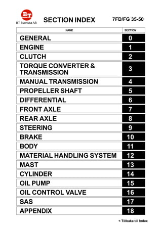
1. SECTION INDEX
NAME SECTION
GENERAL 0
ENGINE 1
CLUTCH 2
TORQUE CONVERTER &
TRANSMISSION
3
MANUAL TRANSMISSION 4
PROPELLER SHAFT 5
DIFFERENTIAL 6
FRONT AXLE 7
REAR AXLE 8
STEERING 9
BRAKE 10
BODY 11
MATERIAL HANDLING SYSTEM 12
MAST 13
CYLINDER 14
OIL PUMP 15
OIL CONTROL VALVE 16
SAS 17
APPENDIX 18
7FD/FG 35-50
< Tillbaka till Index
BT Svenska AB
2. FOREWORD
This manual covers the service procedures of the TOYOTA FORKLIFT
7FG/7FD35 ~ 45 series. Please use this manual for providing quick, correct
servicing of the corresponding forklift models.
This manual deals with the above models as of January 1999. Please under-
stand that disagreement can take place between the descriptions in the manual
and actual vehicles due to change in design and specifications. Any change
or modifications thereafter will be informed by Toyota Industrial Equipment
Parts & Service News.
For the service procedures of the mounted engine, read the repair manuals
listed below as reference together with this manual.
(Reference)
Repair manuals related to this manual are as follows:
TOYOTAG4(GM6-262)ENGINE REPAIR MANUAL
(No.C4630)
TOYOTA11Z,12Z,13Z,14Z ENGINE REPAIR MANUAL
(No.C4615)
3. 0-1
0GENERAL
Page
EXTERIOR VIEWS......................................................... 0-2
VEHICLE MODEL .......................................................... 0-3
FRAME NUMBER........................................................... 0-4
HOW TO USE THIS MANUAL .................................... 0-5
EXPLANATIONMETHOD ................................................. 0-5
TERMINOLOGY................................................................ 0-6
ABBREVIATIONS ............................................................. 0-6
OPERATIONAL TIPS .................................................... 0-7
HOISTING THE VEHICLE ............................................ 0-7
CIRCUIT TESTER.................................................. 0-8
STANDARD BOLT & NUT TIGHTENING
TORQUE ....................................................................... 0-10
BOLT STRENGTH TYPE IDENTIFICATION METHOD ...... 0-10
TIGHTENING TORQUE TABLE ........................................ 0-11
PRECOAT BOLTS ......................................................... 0-12
HIGH PRESSURE HOSE FITTING
TIGHTENING TORQUE ............................................ 0-12
WIRE ROPE SUSPENSION ANGLE LIST ............... 0-13
SAFE LOAD FOR EACH WIRE ROPE
SUSPENSION ANGLE............................................... 0-13
COMPONENTS WEIGHT............................................. 0-14
RECOMMENDED LUBRICANT
QUANTITY & TYPES ................................................. 0-15
LUBRICATION CHART ................................................. 0-16
PERIODIC MAINTENANCE.......................................... 0-18
PERIODIC REPLACEMENT OF PARTS AND
LUBRICANTS............................................................... 0-24
0
5. 0-3
VEHICLE MODEL
7FG35
02-7FG35
7FD35
02-7FD35
7FGK40
02-7FGK40
7FDK40
02-7FDK40
7FG40
02-7FG40
7FD40
02-7FD40
7FG45
02-7FG45
7FD45
02-7FD45
02-7FGA50
02-7FDA50
3.5 ton model
K4.0 ton model
4.0 ton model
4.5 ton model
5.0 ton model
3.5 ton series
4.0 ton series
4.5 ton series
5.0 ton series
M/T
T/C
M/T
T/C
M/T
T/C
M/T
T/C
M/T
T/C
M/T
T/C
M/T
T/C
M/T
T/C
T/C
T/C
Transmission TypeVehicle Model Engine
ModelSeries
Classification
Note:
The G4 engine is the same as the GM6-262 engine except for the nomenclature.
G4
(GM6-262)
G4
(GM6-262)
G4
(GM6-262)
G4
(GM6-262)
13Z
G4
(GM6-262)
13Z
13Z
13Z
13Z
Gasoline
Gasoline
Gasoline
Gasoline
Diesel
Gasoline
Diesel
Diesel
Diesel
Diesel
6. 0-4
FRAME NUMBER
Frame No. Punching Position
Series Engine
G4(GM6-262)
13Z
G4(GM6-262)
13Z
Vehicle model
7FG35
02-7FG35
7FGK40
02-7FGK40
7FD35
02-7FD35
7FDK40
02-7FDK40
7FG40
02-7FG40
7FG45
02-7FG45
02-7FGA50
7FD40
02-7FD40
7FD45
02-7FD45
02-7FDA50
Punching format
EEC spec. models
7FGK40 10011
Other models
7FGK40-10011
EEC spec. models
7FDK40 10011
Other models
7FDK40-10011
EEC spec. models
7FGA50 10011
Other mod ls
7FGA50-10011
EEC spec. models
7FDA50 10011
Other models
7FDA50-10011
Punching position
Punching format
3.5 • K4.0 ton model
4.0 ~ 5.0 ton model
7. 0-5
HOW TO USE THIS MANUAL
EXPLANATIONMETHOD
1. Operation procedure
(1) The operation procedure is described in either pattern A or pattern B below.
Pattern A: Explanation of each operation step with illustration.
Pattern B: Explanation of operation procedure by indicating step numbers in one illustration, fol-
lowed by explanation of cautions and notes summarized as point operations.
Example of description in pattern B
DISASSEMBLY·INSPECTION·REASSEMBLY Tightening torque unit T = N·m (kgf-cm) [ft-lbf]
DisassemblyProcedure
1 Remove the cover. [Point 1]
2 Remove the bushing [Point 2] Operation explained later
3 Remove the gear.
Point Operations Explanation of key point for operation with an illustration
[Point 1]
Disassembly: Put a match mark when removing the pump cover.
[Point 2]
Inspection: Measure the bush inside diameter.
Limit: 19.12 mm (0.7528 in)
• Step Nos. are partially sometimes
omitted in illustrations.
• When a part requiring tightening
torque instruction is not indicated in
the illustration, the part name is de-
scribed in the illustration frame.
T = 46.1 ~ 48.1
(470 ~ 490)
[34.0 ~ 35.5]
8. 0-6
Abbreviation (code)
ASSY
LH
LLC
M/T
OPT
O/S
PS
RH
SAE
2. How to read components figures (Example)
(1) The components figure uses the illustration
in the parts catalog for the vehicle model.
Please refer to the catalog for checking the
part name.
The number at the right shoulder of each
components figure indicates the Fig. num-
ber in the parts catalog.
3. Matters omitted in this manual
(1) This manual omits description of the following jobs, but perform them in actual operation:
Cleaning and washing of removed parts as required
Visual inspection (partially described)
TERMINOLOGY
Caution:
Important matters of which negligence may cause accidents. Be sure to abserve them.
Note:
Important items of which negligence may cause accidents, or matters in operation procedure
requiring special attention.
Standard: Values showing allowable range in inspection and adjustment.
Limit: Maximum or minimum allowable value in inspection or adjustment.
ABBREVIATIONS
Meaning
System of active stability
Special service tool
Standard
Tightening torque
Torque converter &
transmission
Number of teeth ( )
Undersize
With
Less
Meaning
Assembly
Left hand
Long life coolant
Manual transmission
Option
Oversize
Power steering
Right hand
Society of Automotive
Engineers (USA)
Abbreviation (code)
SAS
SST
STD
T =
T/C
T
U/S
W/
L/
-
FIG number in parts catalog
3201
9. 3-14
TORQUE CONVERTER
REMOVAL•••••INSTALLATION T = N•••••m (kgf-cm) [ft-lbf]
Removal Procedure
1 Remove the engine. (See page 1-8.)
2 Drain torque converter oil.
3 Remove the pilot boss.
4 Remove the snap ring.
5 Remove the torque converter.
Installation Procedure
The installation procedure is reverse of the removal procedure.
T = 18.6 ~ 24.5
(190 ~ 250)
[13.7 ~ 18.1]
3
4
5
10. 3-15
DISASSEMBLY•••••INSPECTION•••••REASSEMBLY
Disassembly Procedure
1 Remove the flexible plate.
2 Remove the drive cover. [Point 1]
3 Remove the turbine runner. [Point 2]
4 Remove the thrust bearing.
5 Remove the stator. [Point 3]
6 Remove the pump boss. [Point 4]
Reassembly Procedure
The reassembly procedure is the reverse of the removal procedure.
T = 18.6 ~ 24.5
(190 ~ 250)
[13.7 ~ 18.1]
T = 18.6 ~ 24.5
(190 ~ 250)
[13.7 ~ 18.1]
1 2
3
4
5
T = N•••••m (kgf-cm) [ft-lbf]
T = 18.6 ~ 24.5
(190 ~ 250)
[13.7 ~ 18.1]
11. 3-16
Point Operations
[Point 1]
Disassembly:
Punch a match mark on the drive cover and pump impeller.
Reassembly:
Align the match marks on the drive cover and pump impel-
ler.
Disassembly:
Remove the drive cover.
SST 09950-50012...
SST 09950-60010...
Disassembly:
Remove the bearing.
SST 09950-60010...
SST 09950-70010...
Reassembly:
Bearing installation
1. Temporarily install the pilot boss on the drive cover.
2. Install the bearing.
SST 09950-60010...
SST 09950-70010...
3. Remove the pilot boss.
Install the pilot boss and flexible plate after the torque
converter is installed in the housing.
[Point 2]
Reassembly:
Select the turbine runner spacer before installing the tur-
bine runner as follows.
1. Measure dimension A after temporarily installing the tur-
bine runner (without spacer) on the drive cover.
Remove the O-ring of the pump impeller beforehand.
Match mark
SST
SST
SST
SST
SST
SST
Dimension A
12. 3-17
3
2. Measure pilot boss dimension B and bearing thickness
C.
3. Select the turbine runner spacer so as to satisfy the fol-
lowing equation:
A - (B + C + spacer thickness)
= 0.2 ~ 0.8 mm (0.008 ~ 0.031 in)
Types of spacer thickness:
2.5, 2.7 and 3.0 mm (0.098, 0.106 and 0.118 in)
4. Remove the drive cover, and install the pump impeller
O-ring and the spacer selected above.
[Point 3]
Inspection:
Check the one-way clutch function before removing the
stator.
Disassembly:
Slowly remove the stator hub because rollers, springs and
spring caps come off at a time.
Inspection:
Measure the roller outside diameter.
Standard: 8.30 mm (0.327 in)
Limit: 8.17 mm (0.322 in)
Inspection:
Measure the clearance between the stator hub and stator
cam.
Standard: 0.08 ~ 0.119 mm
(0.0031 ~ 0.00469 in)
Limit: 0.15 mm (0.0059 in)
Reassembly:
Stator installation
1. Apply grease on the springs and spring caps, and install
them with tweezers or a similar tool.
Dimension B Dimension C
13. 3-18
2. Install rollers while pushing each spring cap with a screw-
driver.
3. Install the stator hub on the stator by turning it in the un-
locking direction.
4. Check the one-way clutch function after reassembly.
[Point 4]
Inspection:
Measure the outside diameter at the oil seal sliding surface.
Standard: 70.00 mm (2.7559 in)
Limit: 69.85 mm (2.7450 in)
15. 3-20
Removal Procedure
1 Remove the engine hood. (See page 11-5.)
2 Remove the toe board.
3 Remove the radiator cover.
4 Drain the coolant.
5 Remove the battery and battery tray.
6 13Z engine vehicle:
Disconnect the fuel hose.
Remove the sedimenter bracket set bolt to set the bracket free.
Disconnect the accelerator wire.
7 G4 (GM6-262) engine vehicle: Disconnect the fuel hose.
8 Remove the relay block and electrical parts plate set bolts to set them free.
9 Disconnect connectors and wiring harness clamps around the engine.
10 Disconnect the inching wire.
11 Disconnect the torque converter cooler hose and hydraulic oil cooler hose. [Point 1]
12 13Z engine vehicle:
Remove the radiator and fan shroud.
Disconnect the oil control valve piping.
13 G4 (GM6-262) engine vehicle:
Disconnect the radiator hose.
14 Remove the air cleaner hose.
15 Remove the under cover.
16 Disconnect the exhaust pipe.
17 Remove the oil pump drive shaft ASSY. (See page 15-11.)
18 Remove the propeller shaft. (See page 5-3.)
19 Remove the transmission mounting bolts and pin bolts. [Point 2]
20 Remove the engine mounting nuts.
21 Remove the torque converter & transmission ASSY W/engine. [Point 3]
22 Remove the flexible plate set bolts. [Point 4]
23 Separate the engine from the torque converter housing.
Installation Procedure
The installation procedure is the reverse of the removal procedure.
16. 3-21
3
Point Operations
[Point 1]
Removal:
Put match marks on the fuel hose and the mating joint.
[Point 2]
Installation:
Install the mounting bolt and pin bolt first on the right-hand
side, and then on the left-hand side.
[Point 3]
Removal Installation:
SST 09010-20111-71 .....
09010-23320-71 .....
Move the SST hook position to adjust the balance.
[Point 4]
Removal Installation:
Turn the flywheel using the crankshaft pulley set bolt.
Pin bolt
Mounting bolt
SST
SST
•
•
18. 3-23
DisassemblyProcedure
1 Drain the torque converter oil.
2 Remove the torque converter. (See page 3-14.)
3 Remove the inching valve and solenoid valve. [Point 1]
4 Remove the accumulator and regulator valve. [Point 2]
5 Remove the oil filter. [Point 3]
6 Remove the oil strainer.
7 Separate the torque converter housing. [Point 4]
8 Remove the stator shaft and oil pump. (See page 3-33.)
9 2-speed vehicle: Loosen the main shaft lock nut. [Point 5]
10 Remove the reverse shaft ASSY, main shaft ASSY and F1 shaft ASSY (2-speed vehicle). [Point 6]
11 Remove the reverse shaft bearing, main shaft bearing and F1 shaft bearing (2-speed vehicle). [Point
7]
Reverse clutch shaft parts
12 Remove the reverse clutch gear W/reverse clutch gear bearing and spacer. [Point 8]
13 After removing the snap ring, remove the reverse clutch gear bearing from the reverse clutch gear.
[Point 9]
Main shaft parts
14 1-speed vehicle:
Remove the F clutch gear W bearing and spacer. [Point 10]
15 After removing the snap ring, remove the F clutch gear bearing from the F clutch gear. [Point 11]
16 2-speed vehicle:
Remove the shaft lock nut.
17 Remove the shaft bearing inner race, F2 clutch gear W/clutch bearing outer races No.1.2, clutch gear
bearing inner race No. 1 and spacer. [Point 12]
18 Remove the clutch gear bearing inner race No. 1. [Point 13]
19 Remove the clutch gear bearing outer races No. 1.2 from the F2 clutch gear. [Point 14]
20 Remove the shaft bearing outer race from the torque converter housing. [Point 15]
F1 clutch shaft parts (2-speed vehicle)
21 Remove the F1 clutch gear W/F1 clutch gear bearing and spacer. [Point 16]
22 Remove the F1 clutch gear bearing from the F1 clutch gear. [Point 17]
Counter gear parts (2-speed vehicle)
23 Remove the counter gear W/bearing. [Point 18]
24 Remove the bearing from the counter gear. [Point 19]
Output shaft parts
25 Remove the output shafts No. 1.2 and the output shaft. [Point 20]
26 Remove the output shaft front bearing. [Point 21]
27 Remove the oil seal. [Point 22]
28 Remove the output shaft rear bearing from the output shaft No. 1. [Point 23]
19. 3-24
Point Operations
[Point 1]
Inspection:
Measure the free length of the inching valve spring.
mm (in)
Standard Limit
Inner spring 28 (1.10) 24 (0.94)
Outer spring 64 (2.52) 58 (2.28)
Inspection:
Inspect the solenoid valve for continuity.
F/R:
Between 1 and 2: Continuity
Between 3 and 4: Continuity
F2 (2-speed vehicle)
Between 1 and 2: Continuity
[Point 2]
Inspection:
Measure the free length of the accumulator spring.
mm (in)
Inspection:
Measure the free length of the regulator valve spring.
mm (in)
Standard Limit
Inner spring 150.0 (5.906) 135.0 (5.315)
Outer spring 153.5 (6.043) 138.5 (5.453)
Standard Limit
Inner spring 153.5 (6.043) 135.5 (5.315)
Outer spring 148.0 (5.827) 131.0 (5.157)
[Point 3]
Disassembly Reassembly:
SST 09228-07501
2: F (-) 1: F (+)
4: R (-) 3: R (+)
2: (-)
1: (+)
SST
•
20. 3-25
3
[Point 4]
Disassembly:
Place the torque converter horizontally on wooden blocks
with the engine side facing upward, and separate it by us-
ing the service bolt.
Service bolt size: M10 x 1.5
[Point 5]
Disassembly:
Fix the shaft with a piece of wood inserted between clutch
gears on the front side, and loosen the lock nut.
Reassembly:
1. Temporarily install two clutch shaft ASSY in the housing,
and fix the shaft in the same as at the time of nut loosen-
ing.
2. Use the SST and tighten the shaft lock nut to the speci-
fied torque. (See the instruction manual supplied with
the SST.)
SST 09922-10010
Contact width
Groove width
3. Caulk so that the close contact width exceeds 1/3 of the
shaft groove width.
4. Remove the temporarily installed clutch shaft ASSY, and
wash the housing and clutch shaft ASSY.
[Point 6]
Inspection:
Measure the side clearance of each shaft seal ring.
Limit mm (in)
Main shaft 0.29 (0.0114)
Reverse shaft 0.29 (0.0114)
F1 shaft 0.29 (0.0114)
SST
21. 3-26
[Point 7]
Disassembly:
SST 09950-40011
Reassembly:
SST 09316-60011
[Point 8]
Disassembly:
SST 09950-40011
Reassembly:
After matching the clutch disc serration using a screwdriver,
install the clutch gear.
Reassembly:
1-speed vehicle
SST 09316-60011
While observing the clutch disc state through the side hole
in the clutch drum, gradually install with the clutch drum
side facing upward.
SST
SST
SST
SST
22. Thank you very much for
your reading. Please Click
Here. Then Get COMPLETE
MANUAL. NO WAITING
NOTE:
If there is no response to
click on the link above,
please download the PDF
document first and then
click on it.
23. 3-27
3
When the clutch disc is sticking, move the clutch gear little
by little to let the clutch disc fall.
Reassembly:
2-speed vehicle
1. Insert a plate between the clutch gear and clutch drum
as illustrated, and temporarily install the gear first.
2. Install the clutch gear bearing on the clutch gear.
SST 09316-60011
3. Remove the plate, and use the SST to install the clutch
gear W/clutch gear bearing.
[Point 9]
1-speed vehicle
Disassembly Reassembly:
SST 09950-60010 .....
09950-70010 .....
2-speed vehicle
Disassembly:
SST 09950-60010 .....
SST 09950-70010 .....
Reassembly:
Reassemble after temporarily installing the clutch gear. (See
Point 8.)
[Point 10]
Disassembly:
SST 09950-40011
SST
SST SST
SST
SST
SST
SST
SST
0~2mm
(0~0.079in)
•
24. 3-28
Reassembly:
1. Insert as plate as illustrated between the clutch gear and
clutch drum, and temporarily install the gear first.
2. Install the clutch gear bearing on the clutch gear.
SST 09316-60011
3. Remove the plate, and use the above SST to install the
clutch gear W/clutch gear bearing.
[Point 12]
Disassembly:
SST 09950-40011
Disassembly:
Take a note of the bearing composition so as not to install
in an incorrect order.
Reassembly:
Use the SST and temporarily reassemble the clutch gear
bearing outer race, F2 shaft bearing and spacer to the state
allowing lock nut tightening.
SST 09316-60011
[Point 11]
Disassembly:
SST 09950-60010 .....
SST 09950-70010 .....
Reassembly:
Reassemble after temporarily installing the clutch gear. (See
Point 10.)
SST
SST
SST
SST
SST
SST
SST
[Point 13]
Disassembly:
SST 09950-40011 .....
09950-30010 .....
Use the SSTs in combined state.
0~2mm
[0~0.079in]
25. 3-29
Reassembly:
SST 09316-60011
[Point 14]
Disassembly:
SST 09308-00010
Carefully operate so that the claw of the SST does not catch
the snap ring.
Take a note of the bearing outer race mounting position.
Reassembly:
SST 09950-60020 .....
09950-70010 .....
[Point 15]
Disassembly:
SST 09308-00010
Reassembly:
SST 09950-60020 .....
09950-70010 .....
SST
SST
SST
SST
SST
SST
SST