Technical Seminar on Automatic vehicle communication systems
1.
T E CH N I C A L S E M I N A R P R E S E N T A T I O N O N
Autonomous Vehicle
Communication Systems
Siddhi Haarika Jagerkal
22251A1712- ETM
G. Narayanamma Institute of Technology and Science, Telangana 500104
Department of Electronics and Telematics Engineering
2.
C O NT E N T S
Introduction
History
Features
Construction
Working
Advantage
Disadvantage
Case Studies
Conclusion
Future Scope
3.
Introduction
• AVCS refersto the technology that allows
vehicles to exchange information with their
surroundings.
• Vehicles communicate with other vehicles,
roadside units, pedestrians, and cloud
servers.
• This communication helps a vehicle
understand the environment beyond what
sensors can see.
• AVCS creates a connected road ecosystem
that supports safer and smarter mobility.
4.
Why Communication IsCrucial for
Autonomous/Connected Driving
• Sensors have limited range and cannot detect hidden
obstacles, blind spots, or events happening far ahead;
communication fills these gaps by delivering real-time
updates and early warnings that extend a vehicle’s
awareness beyond its sensors.
• By enabling vehicles to coordinate braking, lane
changes, and merging, AVCS reduces human error,
improves traffic flow, enhances overall safety, and
supports the higher levels of automation required for
fully connected and autonomous driving.
5.
Types of V2Xcommunication
• V2V (Vehicle-to-Vehicle)
Shares speed and position data between vehicles to avoid
collisions and support cooperative driving.
• V2I (Vehicle-to-Infrastructure)
Communicates with traffic lights and roadside units for
signal timing, hazards, and traffic control.
• V2P (Vehicle-to-Pedestrian)
Provides alerts between vehicles and pedestrians/cyclists
through mobile devices for safety.
• V2N (Vehicle-to-Network)
Connects vehicles to cloud services for navigation, traffic
updates, diagnostics, and OTA updates.
• V2X (Vehicle-to-Everything)
Unified system combining all V2V, V2I, V2P, and V2N
communication for a fully connected ecosystem.
6.
Early Experiments (1920s–1960s)
•1925: First radio-controlled car “American Wonder” demonstrated on New York
streets — the earliest idea of a driverless vehicle.
• 1939–1940: Futurama exhibit at the New York World’s Fair showcased guided
electric cars running on embedded roadway circuits.
• 1950s: RCA Labs and Nebraska State Roads tested full-scale cars guided by wires
and roadside signals — one of the first true automated driving demonstrations.
• 1960s: UK and US research labs tested cars controlled by magnetic cables and
roadside electronics, proving high-speed automated lane following.
History
7.
History
Shift Toward On-BoardIntelligence (1970s–1980s)
• 1977: Tsukuba Mechanical Engineering Lab (Japan) built the first self-
driving car using cameras and analog computing.
• 1980s: Vision-based autonomy emerged — Mercedes-Benz and University
of Munich demonstrated robotic vans driving up to 95 km/h.
• 1984–1989: Carnegie Mellon University’s Navlab and ALV projects pioneered
computer vision, lidar, and early neural-network-based vehicle control.
• 1987–1995: Europe’s Eureka PROMETHEUS Project became one of the
largest autonomous vehicle research programs, testing long-distance
autonomous highway driving.
8.
History
Modern Autonomous SystemsEmerge (1990s–2000s)
• 1990s: US Automated Highway System demonstrated platooning and
automated driving lanes on public highways.
• 1995: CMU’s “No Hands Across America” completed a 5,000 km partially
autonomous road trip.
• Late 1990s: First commercial concepts of radar-based braking, adaptive
cruise control, and lane keeping appeared.
• 2004–2007: DARPA Grand Challenges transformed autonomy —
introducing robust lidar, vision, GPS fusion and urban navigation.
9.
History
Modern Era: TechCompanies, Automakers & Regulations (2010s–Present)
• Google/Waymo began large-scale autonomous driving tests, leading to commercial
robotaxi trials.
• Aptiv (formerly Delphi) conducted a landmark coast-to-coast autonomous drive
(2015) and later partnered in global robotaxi deployments.
• GM, Ford, Tesla, Mercedes-Benz, Nissan, Toyota, Audi, and Volvo launched strong
self-driving research programs integrating AI, lidar, radar, and V2X communication.
• Cities in the EU, Japan, and the U.S. introduced laws enabling Level 2–4 automation
on public roads.
• Today’s systems combine advanced sensing with Vehicle-to-Everything (V2X)
communication, forming the backbone of future autonomous mobility.
10.
Features
• Visibility (Perception)
Sensesenvironment: traffic,
objects, infrastructure.
• Decision (Planning)
Plans path, predicts behavior,
selects safe actions.
• Orientation (Localization)
Determines vehicle position and
direction.
Enabling Technologies
Sensors: LiDAR, Radar,
Cameras, Ultrasonic
Data Sources: GPS, HD Maps
Communication: V2V, V2I, IoT
11.
Features
• Uses multiplesensors (LiDAR, Radar,
Cameras, Ultrasonic) to sense the
environment
• Fusion ECU combines data to create a
single, accurate 360° view
• Improves detection of vehicles,
pedestrians, road signs, and obstacles
• Reduces blind spots and enhances
performance under poor visibility
Multi-Sensor Perception & Fusion
12.
Features
• Enables vehiclesto exchange
information with other cars,
infrastructure, pedestrians, and cloud
• Provides data on traffic, road
conditions, signal timing, and hazards
beyond line-of-sight
• Ensures ultra-low latency messaging for
safety-critical decisions
• Supports cooperative behaviors like
merging, platooning, and intersection
management
Real-Time Communication (V2X)
13.
Features
Key Functional Featuresof an Autonomous Vehicle
How an Autonomous Vehicle Works
Collects Data:
Uses communication modules & sensors
(camera, radar, LiDAR) to perceive the
environment.
Makes Decisions:
On-board AI/ECU processes data for path
planning, obstacle avoidance, and optimal
driving actions.
Actuates Controls:
Executes decisions through steering,
braking, and acceleration actuators to
achieve the desired motion.
14.
Features
Automatic Emergency Braking(AEB) – Collision Avoidance Timeline
How AEB Responds Before a Collision
~2.6 sec before impact:
Vehicle detects threat → gives visual &
acoustic collision warnings.
~1.6 sec before impact:
If the driver doesn’t react → system applies
partial braking (PRE-SAFE brake
activation).
~0.6 sec before impact:
Final chance to avoid crash → system
performs emergency braking or evasive
steering.
Construction
Sensor Layer: EnvironmentPerception
LiDAR – Generates 3D map, detects object
shape & distance
Radar – Measures range & relative velocity
in all weather
Cameras – Detect lanes, signs, traffic
lights, pedestrians
Ultrasonic Sensors – Short-range obstacle
detection for parking
GPS + IMU + Odometry – Provides precise
localization & orientation
Multi-sensor Fusion – Combines all inputs
for a reliable 360° environment model
17.
Construction
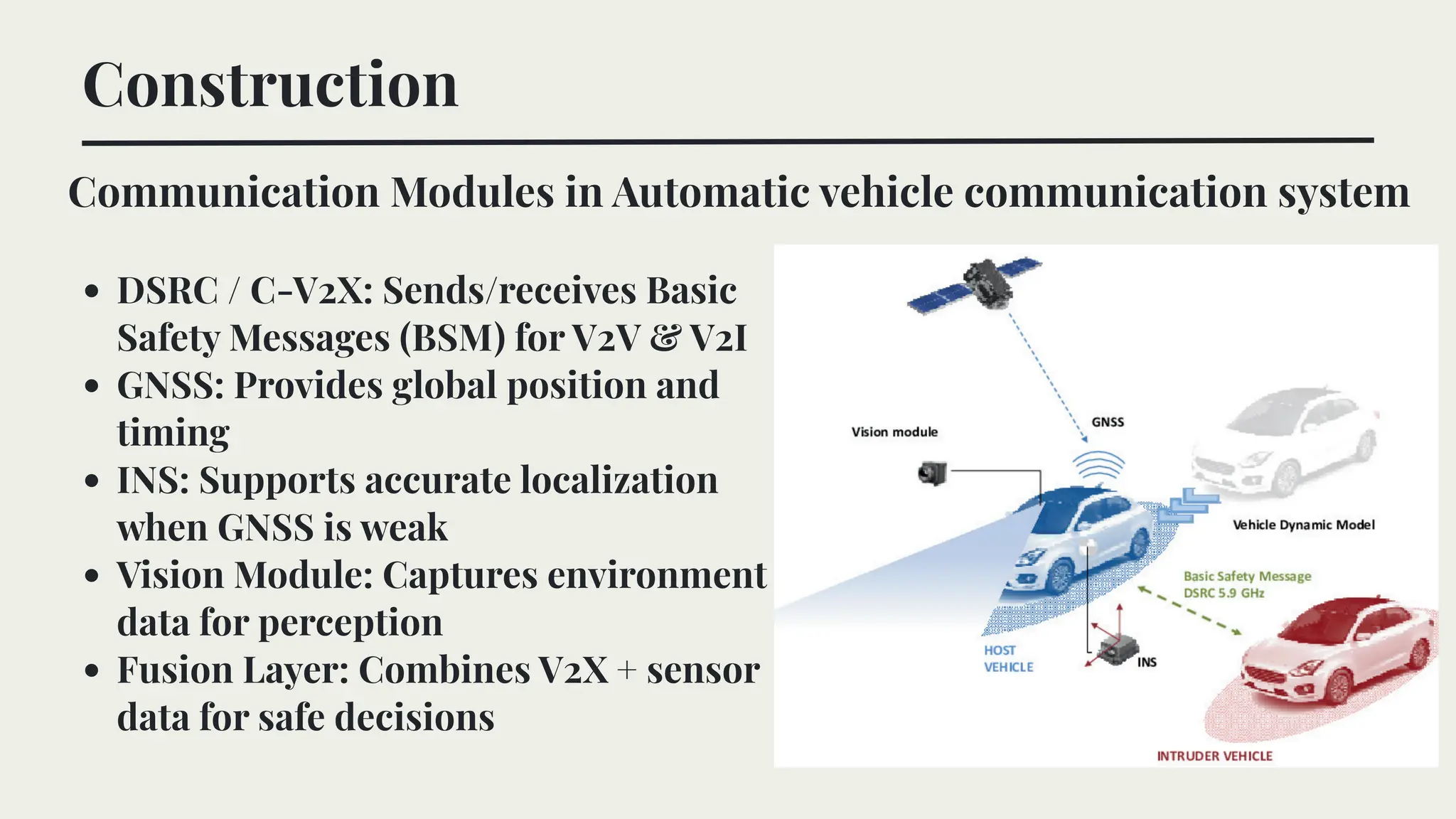
Communication Modules inAutomatic vehicle communication system
DSRC / C-V2X: Sends/receives Basic
Safety Messages (BSM) for V2V & V2I
GNSS: Provides global position and
timing
INS: Supports accurate localization
when GNSS is weak
Vision Module: Captures environment
data for perception
Fusion Layer: Combines V2X + sensor
data for safe decisions
18.
Construction
Central Computing Unit(ECU)
Processes sensor inputs and runs core driving algorithms
Performs sensor fusion, decision-making, and control commands
Sends outputs to actuators via CAN/LIN for steering, braking, and throttle
19.
Construction
How V2X DataFlows Inside the Vehicle
V2X module receives external messages (BSM, MAP, SPaT, hazard alerts) via PC5 or Uu
interface.
ECU fuses V2X data with onboard sensor data to understand surroundings.
Planner generates safe action → actuators execute braking, steering, or speed changes.
20.
Construction
Actuator Subsystem
Actuators executethe ECU’s
decisions using by-wire systems
(steer-by-wire, brake-by-wire,
throttle-by-wire).
Steering, braking, and acceleration
are controlled electronically for
precise and real-time motion
control.
V2X alerts integrated into ECU
enable automatic emergency
braking, lane correction, and
speed adjustment.
21.
Working
Multi-channel sensing &positioning:
The vehicle continuously gathers real-time data
using onboard sensors (camera, radar, LiDAR) and
GNSS for precise location.
V2X communication exchange:
The car directly communicates with nearby
vehicles , roadside units , pedestrians/devices , and
cellular towers/cloud servers to receive hazard
alerts, traffic updates, and control information.
Coordinated decision-making:
The ECU fuses sensor data + V2X messages to
predict risks and selects safe maneuvers, which
are executed via steering, throttle, and braking
actuators.
Overall Working Overview
Working
V2X Message Exchange
Vehicles,pedestrians, and infrastructure continuously exchange safety messages (V2V,
V2P, V2I) using DSRC/5G to share real-time data like speed, location, and hazards.
The cloud/network (V2N) processes and distributes broader updates—traffic
conditions, accidents, roadwork—ensuring coordinated and safer driving decisions.
24.
Working
AVCS processes sensor+ V2X data
to extract traffic scene
characteristics (objects, speed,
road geometry).
The ECU applies prediction &
optimization models (e.g., SVR,
PSO) to generate the safest driving
decision.
Final commands are sent to the
control system for steering,
braking, and speed adjustments.
Decision-Making Flow
25.
Working
ECU Processing Pipeline
ECUcombines sensor + V2X data for perception, planning, and control.
Perception builds environment model + localizes vehicle.
Planning selects safest path; control sends commands to actuators.
26.
Working
Path Planning
Global Plannerselects long-distance route using maps & traffic data.
Local Planner adjusts path moment-to-moment around obstacles.
Ensures a smooth, collision-free trajectory under dynamic conditions.
27.
Working
Collision Avoidance Working
ECUmonitors distance and
relative speed using sensors +
V2X alerts.
If collision risk is high, system
triggers FCW and prepares
braking.
If no driver response, AEB or
lane correction activates to
avoid or reduce impact.
28.
Working
Sensor data collectionand actuator working
ECU converts planned maneuvers
into steering, throttle, and braking
commands.
Drive-by-wire actuators execute
these commands with high
precision.
Continuous sensor feedback ensures
smooth, stable, and accurate vehicle
motion.
29.
Advantages -Technical &Safety Advantage
1. Reduced Collision Risk Through Real-Time Sensor Fusion
AVCS integrates LiDAR, RADAR, cameras, and V2X inputs to detect hazards with
millisecond latency.This increases reaction speed beyond human capability,
enabling automatic emergency braking (AEB), adaptive cruise control, and blind-
spot monitoring that are already deployed in modern ADAS systems.
2. Cooperative Awareness via V2V/V2I Communication
Vehicles share position, speed, and intent using DSRC/PC5 links, enabling
cooperative collision avoidance, intersection movement assistance, and platooning.
These systems reduce multi-vehicle pileups and improve predictability in dense
traffic.
3. Improved Trajectory Planning Accuracy
Advanced ECUs use high-frequency prediction models and motion planning
algorithms (MPC, RRT, behavior prediction) to compute safe, dynamically feasible
paths.This reduces lane-drift, unsafe turns, and human reaction delay errors.
30.
Advantages - Operational,Mobility & Efficiency
1. Increased Accessibility for Non-Drivers
AVCS provides navigation and safety automation for elderly, disabled, and
unlicensed users, supported by lane-keeping assist, automated parking, and
remote-operation capabilities used in robo-taxis today.
2. Traffic Flow Optimization Through Connected Automation
Vehicle platooning, cooperative merging, and real-time traffic coordination
decrease stop-and-go waves, smoothing highway flow and reducing congestion by
up to 22% in field trials (e.g., PATH, EU C-ITS pilots).
3. Energy Efficiency & Emission Reduction
Smooth acceleration profiles and coordinated driving reduce unnecessary braking
and acceleration.
This results in 5–15% lower fuel consumption in real-world connected platoon
trials and improves environmental impact.
31.
Drawbacks - TechnicalLimitations
1. Sensor Reliability Issues in Real Environments
LiDAR, radar, and camera performance degrades under fog, rain, snow, glare, and
occlusions, leading to reduced perception accuracy and unstable
detection/tracking.
2. High Computational Load & Latency Constraints
Real-time sensor fusion, object prediction, and planning require high-
performance ECUs. Any latency spike (even >10 ms) can cause unsafe decision
delays, especially at high speeds.
3. V2X Communication Vulnerabilities
DSRC/C-V2X links can suffer from packet loss, low penetration rate, network
congestion, or signal blockage. Low adoption of V2X-equipped vehicles limits the
effectiveness of cooperative safety functions.
32.
Drawbacks -Security, Cost& Deployment
1. Cybersecurity Risks
AVCS exposes multiple attack surfaces: sensors, ECUs, CAN bus, and V2X
messages.
Spoofing, jamming, or injection attacks can manipulate perception, causing
false braking or incorrect decisions.
2. High Cost of Sensors & Infrastructure
LiDAR units, high-resolution radars, safety-grade ECUs, and V2X modules are
expensive.
Full AVCS deployment requires RSUs, edge servers, and 5G coverage, which
most regions still lack.
3. Dependence on High-Definition Maps & Cloud
AVCS performance drops if HD maps are outdated, incomplete, or unavailable.
Cloud dependence for updates and cooperative perception introduces latency
and connectivity issues.
33.
Case Study 1- Tesla Autopilot
Tesla AVCS uses a camera-dominant
sensor suite supported by
ultrasonics and radar (older models).
All sensors feed into a centralized
Autopilot ECU (HW3) capable of ~144
TOPS.
Architecture supports real-time
object detection, lane modeling,
vehicle tracking.
Overview & System Architecture
34.
Case Study 1- Tesla Autopilot
How Tesla AVCS Works
Vision stack converts camera frames into a unified vector space representation.
Neural planner predicts multi-modal trajectories under uncertainty.
Explicit control module issues steering, throttle, and brake commands.
35.
Case Study 1- Tesla Autopilot
Achievements & Technical Limitations
Achievements
Scalable vision-only system replacing expensive LiDAR.
Autopilot reduces collision rate by up to 40–50% (NHTSA-reported
improvements).
Neural network planning enables smoother lane selection and merges.
Limitations
Vision-only stack struggles in heavy rain, fog, snow, and low-contrast
conditions.
System heavily reliant on data availability and fleet training.
Edge-case failures (crossing traffic, debris, unusual lighting) still require
human supervision.
36.
Case Study 2-Google Waymo
Waymo System Architecture
Waymo Driver uses multi-sensor fusion
(LiDAR, radar, cameras, GPS/IMU) to
build a 360° environment model.
Perception module performs object
detection + classification + tracking in
real time.
Prediction module forecasts trajectories
of vehicles, pedestrians, and cyclists using
ML behavior models.
Planning & Low-Level Control generate a
safe path and execute steering, throttle,
and brake commands.
37.
Case Study 2-Google Waymo
How Waymo Driver Works
The system builds a real-time
3D understanding of the
environment using fused
LiDAR, radar, camera, and HD-
map data.
Behavior prediction models
estimate future motions of
surrounding agents (vehicles,
pedestrians, cyclists).
A trajectory planner selects the
safest maneuver while
respecting traffic rules, road
geometry, and comfort
constraints.
38.
Case Study 2-Google Waymo
Achievements vs Technical Limitations
Conclusion
Autonomous Vehicle CommunicationSystems represent one of the most
transformative innovations in modern transportation. By integrating
multi-sensor perception, high-speed V2X communication, intelligent
decision-making algorithms, and precise actuation, AVCS enables vehicles
to operate with greater awareness, coordination, and safety than human-
driven systems.
Through the case studies of Tesla, Waymo, and Aptiv, it is clear that
different architectural approaches exist, yet all move toward the same goal:
real-time situational understanding and cooperative mobility. AVCS
significantly improves road safety, reduces congestion, enables predictive
driving, and forms the backbone of future smart-city ecosystems.
41.
Conclusion
While challenges remain—suchas handling rare scenarios, ensuring
cybersecurity, maintaining communication reliability, and achieving
regulatory acceptance—the technological progress is rapid and
compelling. With continuous advancements in AI, 5G/6G
communication, edge computing, and sensor fusion, AVCS is steadily
steering the automotive industry toward fully autonomous, connected,
and sustainable transportation networks.
In conclusion, AVCS is not just a subsystem of autonomous vehicles—it
is the core enabling technology that will define the future of mobility.
Future Scope
6G-enabled V2Xcommunication will provide sub-millisecond latency, higher spectrum
efficiency, and support for massive vehicular networks, enabling cooperative perception
and coordinated maneuvers.
Edge AI + On-board Accelerators will enable real-time decision-making, continuous
learning, and improved prediction of rare or complex road scenarios.
Dynamic, Crowdsourced HD Maps updated in real time will reduce dependence on static
pre-mapped regions and improve scalability across cities.
Cooperative Driving & Platooning will optimize traffic flow, reduce fuel consumption, and
increase road capacity through synchronized vehicle movements.
Secure V2X Frameworks (blockchain-based authentication, quantum-resistant encryption)
will address cybersecurity threats and safeguard vehicular communication.
Integration with Smart Infrastructure such as intelligent traffic signals, smart RSUs, and
citywide mobility platforms will enable fully connected urban ecosystems.
Standardization & Regulatory Evolution will accelerate deployment, ensuring safety,
interoperability, and global adoption of autonomous mobility systems.


![[DSC Europe 25] Velibor Ilic - Autonomous Driving - How AI Shapes Technical ...](https://cdn.slidesharecdn.com/ss_thumbnails/gwu9aqths9ovngsrhidc-3-velibor-ilic-autonomous-driving-how-ai-shapes-technical-challenges-251219150035-7436923a-thumbnail.jpg?width=640&height=640&fit=bounds)


