2. Introduction
• One piece of equipment without which the modern
clinical practice of RPD would not be possible is the
Surveyor.
• The turning point in the change of partial denture
construction from guesswork based on clinical
experience to scientifically based procedure was the
appearance of the dental surveyor in 1918.
3. Introduction
• In 1954, Applegate commented that the intelligent
use of the dental surveyor is the best way to prevent
the occurrence of countless problems frequently
related to oral rehabilitation with RPDs.
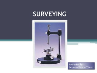
4. SURVEYOR
• Surveyor is a parallelometer, an
instrument used for determining
the relative parallelism of two or
more surfaces of the teeth or
other areas on a cast of the jaws.
(Stewart)
• ‘A paralleling instrument used in
construction of a prosthesis to
locate and delineate the contours
and relative position and
abutment teeth and associated
structures’ (GPT-8)
5. SURVEY-
• ‘The procedure of locating and delineating the
contour and position of the abutment teeth and
associated structures before designing a removable
partial denture’. (GPT-8)
SURVEYING –
• ‘An analysis and comparison of the prominence of
intraoral contours associated with the fabrication of a
prosthesis’ (GPT-8)
6. DEVELOPMENT OF DENTAL SURVEYOR
Journal of Prosthodontics, Vol 11, No 1 (March), 2002: pp 11-18
Journal of Prosthodontics, Vol 11, No 2 ( June), 2002: pp 122-130
7. Eyeballing ….
• Before the investigation of dental
surveyor, dentist evaluated axial
contours and undercut of teeth by
visual survey of dental cast.
• Technique developed by W.M. Randall
in 1920.
• Cast stabilized by wax or compound.
8. The cast is then eyeballed-
viewing the cast with one eye
closed.
One sharp pencil is hold with
hand perpendicular to occlusal
plane, the practitioner would
pass a pencil lead over the axial
surfaces of the teeth to develop
a survey line at the greatest
diameter of each tooth.
Eyeballing…
9. • 1918- Dr. A J Fortunati is thought to be the
first person to employ a mechanical device to
determine the relative parallelism of tooth
surface.
• At a clinic in Boston he demonstrated a method
of charting correct clasp placement by using a
parallelometer with graphite rod.
• Dr. Kennedy was later credited with coining the
term “height of contour”.
10. • Paralleling devices were
in use long before the
development of dental
surveyor.
• Used to assure proper
alignment of precision
attachment and also used
to identify nonparallel
and/or undercut surfaces
of prepared teeth.
11. THE FIRST DENTAL SURVEYOR
• Developed by NEY in 1923 featured
a convenient palm rest on the top of
the vertical arm.
• Designed by Weinstein and Roth
THE ORIGINAL NEY SURVEYOR
14. • The austenal microanalyser measures undercut
electronically, and a dial indicator shows the
desired amount of undercut, and a flashing light
signals when the exact undercut is reached
15.
16. Dental surveyors have been
developed to function as milling
machines or drill presses.
Developed for precision
attachment applications, these
instruments ensure the parallelism
of guiding planes milled into
castings.
17. • Ney Surveyor
• Jelenko Surveyor
• Williams Surveyor
• The Retentoscope
• The Ticonium
surveyor
• The Micro-Analyzer
TYPES OF DENTAL SURVEYOR
18. • Ney Surveyor
• Jelenko Surveyor
• Williams Surveyor
• The Retentoscope
• The Ticonium
surveyor
• The Micro-Analyzer
TYPES OF DENTAL SURVEYOR
19. • Ney Surveyor
• Jelenko Surveyor
• Williams Surveyor
• The Retentoscope
• The Ticonium
surveyor
• The Micro-Analyzer
TYPES OF DENTAL SURVEYOR
20. • Ney Surveyor
• Jelenko Surveyor
• Williams Surveyor
• The Retentoscope
• The Ticonium
surveyor
• The Micro-Analyzer
TYPES OF DENTAL SURVEYOR
21. • Ney Surveyor
• Jelenko Surveyor
• Williams Surveyor
• The Retentoscope
• The Ticonium
surveyor
• The Micro-Analyzer
TYPES OF DENTAL SURVEYOR
22. PRINCIPLE Of WORKING
If a vertical plane is
brought into contact
with a curved surface, it
will touch at the greatest
bulge on the convexity
and nowhere else.
23. PARTS OF DENTAL SURVEYOR
Vertical
arm
Horizontal arm
Surveying arm
Surveying table
Surveying platform
Mandrel with
attached analyzing
rod
24. PARTS OF SURVEYOR
1. Platform on which the
cast holder is moved
2. Vertical arm that
supports
superstructure
3. Horizontal arm from
which surveying tool
suspends .
2
1
3
25. PARTS OF A SURVEYOR
4. Surveying table or cast
holder to which the
cast is attached.
5. Base on which the
table swivels
6. Analyzing rod or
Paralleling tool or
guideline marker
4
5
6
26. 7. A surveying arm that drops
vertically from the
horizontal arm .
• The surveying arm is
capable of movement in
vertical direction .
8.Mandrel for holding special
tools as Carbon marker,
analyzing rod, wax trimmer
and undercut gauge
8.
7.
PARTS OF A SURVEYOR
28. • Analyzing rod:- This metal rod is placed against
the teeth and the ridge during the initial analysis
of the cast to identify undercut areas and areas
of parallelism without marking the cast.
Analyzing Rod
29. • The graphite marker is moved along the teeth and
the alveolar ridge to identify and mark the
position of maximum convexity. (SURVEY LINE)
Graphite(Carbon) marker
30. • They are used to determine the amount and location of
retentive undercut on the surface of an abutment tooth
and are available in sizes; 0.010inch, .015 inch and 0.020
inch (Mccracken- .010inch, .020 inch, .030inch)
Undercut gauge
31. Chisel (Wax Trimmer)
Trimming Knife: Wax is added to block the
unwanted undercut and the wax trimmer is
used to remove the excess wax.
32. USES OF SURVEYOR
• Surveying the diagnostic cast
• Contouring wax patterns
• Placement of internal rest seat
• Surveying the master cast
• Recontouring abutment teeth on the diagnostic
cast
• Aids in placing guide plane
• Measuring depth of undercut on abutment
tooth
33. Survey lines
• “A line drawn on a tooth or teeth of a cast by means of a
surveyor for the purpose of determining the position of
various parts of a clasp or clasps”- GPT 8
• Survey line are nothing but height of contour of a
teeth marked by carbon marker.
34. Survey line divides tooth in two parts :
: Occlusal to survey line.
Its provide support.
Apical to survey line
It is for retention
35. • CLASSIFICATION OF SURVEY LINE: BLATTER
FEIN SYSTEM:
He introduced the terms Near Zones and Far Zone.
Near Zone- is the half which lies nearer to the saddle
or edentulous area.
Far Zone- is the half which is away from the saddle.
• According to Blatterfein, survey lines are
The high survey line.
The medium survey line.
The low survey line.
The diagonal survey line.
36. High Survey Line
• This survey line
appears near to the
occlusal than the
gingival of the tooth in
both near and far
zones.
• found on the lingual
surfaces of lower teeth
and on buccal surface
and uppers.
37. It passes from the
middle third of the
tooth in the near zone
to the gingival third of
the tooth in the far
zone.
Medium Survey Line
38. Low Survey Line
Very low on the buccal
or lingual aspect of a
tooth.
Marked inclination of
the tooth, also found
on the conically
shaped tooth.
39. Diagonal Survey Line
• These types of survey
lines are present near the
occlusal surfaces of near
zone to cervical surface of
far zone.
• Such lines are most
commonly found on the
buccal surface of canines
and premolars
41. • A color coding system for the various parts of the
removable partial denture as well as for other items
of information that should be included on the
diagnostic casts helps prevent confusion on the part
of a dental laboratory technician or any one trying
to understand the design being proposed.
42. • Brown crayon pencil out line the metallic
portion.
• Blue crayon pencil out line the acrylic portion of
the denture base.
• Red crayon pencil to indicate areas on the teeth
that will be prepared.
• Solid red rests and rest seats.
• Black pencil and carbon marker used to denote
the survey lines
43. SURVEYING-TILTING
• Initially when the cast is placed on the table the occlusal
surface is made parallel to the platform.
• However the final tilt of the cast at which the surveying is
done is decided on the basis of the path of insertion to be
selected.
• To achieve that the table can be tilted in different direction:
1. Anterior tilt.
2. Posterior tilt
3. Lateral Tilt.
44. • Anterior tilt:- the anterior of
the cast is lowered
• Posterior tilt:- the posterior
of the cast is lowered.
• Right tilt:- the right side of
cast is lowered, as viewed from
the rear.
• Left tilt:- the left side of cast
is lowered .
• Any combination of tilt may be
used, but excessive tilt must be
avoided.
45. Use right or left tilt for casts which have one abutment
tooth abnormally aligned.
• For example, if a lower left molar is tipped badly to the
lingual, the path of insertion must be from right to left to
favor the tipped tooth.
SURVEYING-TILTING
46. • The tilt may be changed to accomplish specific
purpose, but exaggerated tilt (more than 10
degrees from the horizontal )must be avoided.
47. Tripoding…
• After the final tilt of the cast has
been selected, it must be
recorded so that the cast may
later be repositioned precisely
known as tripoding.
Method-
• Place three cross marks on the
tissue portion of the cast ,lingual
to the remaining teeth at widely
separated points while the cast
and vertical arm of the surveyor
are held at fixed positions.
• This will established 3 point on
the same horizontal plane.
48. Transferring tripod marks to
another cast
• Three points selected from the
diagnostic cast must be identified and
with the analyzing rod held at a fixed
vertical position, the cast is tilted in
various ways until the tip of analyzing
rod contacts the points on the same
horizontal plane.-the tilt of both the
cast is now exactly the same.
• Reference points are: Distal marginal
ridge of the first premolar, the incisal
edge of the lateral incisor, and the
lingual cusp tip of the left first
premolar.
49. Surveying the Master Cast
The following factors are checked during survey of the
master cast :
Parallelism of the guiding plane
Depth of undercuts and retention
Height of contour
Interference
Aesthetics
51. Retentive undercuts
• Retentive areas must exist for a
given path of placement & must be
contacted by retentive arms
• If retentive undercut are not
present they must be created-
enamel surface can be contoured in
limited.
52. • Ideally, proposed abutment teeth should have 0.010
inch of undercut at the most desired location-
Distobuccal or mesiobuccal line angle and in gingival
third of the clinical crown of the teeth.
• Normally tilt is changed to lower the height of contour
of an abutment teeth so that a clasp be positioned no
more occlusal than the junction of gingival and
middle third of the teeth-improves esthetic and
lowering rotational forces the clasp transmit the teeth.
53. INTERFERENCE
• The prosthesis must be placed & removed without
interference with tooth & soft tissue structure.
• Interference may be eliminated during mouth
preparation by surgery, extraction, modifying
interfering tooth surfaces, or altering tooth
contours with restorations
54. INTERFERENCE
• Interferences in the mandible
1. Lingual tori
2. Bony exostoses
3. Lingually inclined teeth.
• Interference in the maxilla :
1. Torus platinus
2. Bony exostoses
3. Buccal tipped teeth.
55. AESTHETICS
• Clasp arms must be concealed. Positioning the clasp arm
at a lower level will help to conceal the clasp arm.
• A balance should be obtained between aesthetics and
function.
• The artificial anterior teeth should be placed in the same
position as the natural teeth.
56. GUIDING PLANES
• Two or more parallel axial surfaces on abutment
teeth can be used to limit the path of insertion and
improve the stability of a removable prosthesis.
• Need not to be more than 2-3mm in occluogingival
height.
• Surveyor is used to locate existing or potential
surface of teeth that can be converted to guiding
planes by selective grinding.
57. GUIDING PLANES
Functions of a guiding plane:
• Makes insertion and removal of the prosthesis
easier.
• It minimizes the wedging stresses on the abutments.
• Aids to stabilize the prosthesis against horizontal
stresses
• Aids to stabilize individual teeth.
60. • A 3-dimensional computer model of a conventional cast
from a patient is obtained using an optical surface
capture device (a scanner)
• The shape of number of components of a removable
partial denture framework was modeled on the 3-
dimensional scan electronically, using computer- aided
design software.
• A physical plastic shape of the components was
produced using a Rapid Prototyping machine and used
as a pattern used as a pattern.
61.
62. Use of cad-cam technology to fabricate a removable partial
denture framework removable partial denture framework
• This is the first patient
fitted cobalt-chromium
fitted cobalt-chromium
RPD framework produced
by cad-cam and rapid
prototype technology.
63.
64. Conclusion
• The many advantages gained by the intelligent
use of the dental surveying instrument have been
discussed.
• The application of the surveyor is not limited to
removable partial dentures but is equally
effective as a diagnostic and treatment planning
aid in fixed partial dentures, complete dentures.
65. References
• REMOVABLE PARTIAL DENTURE by McCraken
• A CLINICAL GUIDE TO REMOVABLE PARTIAL DENTURE by J.C.
DAVENPORT et al
• CLINICAL REMOVABLE PARTIAL PROSTHODONTICS by Stewart