
Recommended
More Related Content
More from eyyh5611017
More from eyyh5611017 (12)
Still Electric Fork Truck Forklift R20-20 Series Service Repair Manual 1.pdf
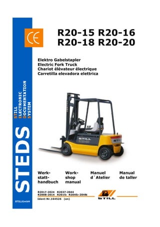
- 1. STILLGmbH R20-15 R20-16 Werk- statt- handbuch Work- shop manual Manuel d´Atelier R2008-2014 R2015 R2045 -2048 I I I R2017-2024 R2037-2044 R20-18 R20-20 Elektro Gabelstapler Electric Fork Truck Chariot élévateur électrique Carretilla elevadora elettrica Manual de taller Ident-Nr.164526 (en)
- 2.
- 3. STILL GmbH Position as per: 4/2002 ( Replaces version: ) 01 Workshop Manual 2008 - 14, 2015 i, 2018 - 24 01 Table of Contents Page Frame and Counterweight 2 Jacking up the truck 3 Chassis Frame
- 4. STILL GmbH Position as per: 4/2002 ( Replaces version: ) 01 Workshop Manual 2008 - 14, 2015 i, 2018 - 24 Frame and counterweight 02 Frame The welded steel frame is of unit instruction and has bolt-on cast iron counterweight. Counterweight The removable counterweight is secured to the frame by four bolts (see sketch). 1 = Hex head bolt M 24 x 110 / 8.8 2 = Spherical washer 3 = Ball cup The counterweight bolts(item 1) should be tor- qued to 660 Nm. 2010 -- 798 kg 2008 / 2011 -- 858 kg 2009 / 2012 -- 902 kg 2013 / 2014 -- 902 kg 2015 / 2018 -- 861 kg 2019 / 2022 / 2023 -- 891 kg 2020 -- 832 kg 2021 -- 875 kg 2024 -- 1009 kg 1 2 3 1 2 3
- 5. STILL GmbH Position as per: 4/2002 ( Replaces version: ) 01 Workshop Manual 2008 - 14, 2015 i, 2018 - 24 Jacking up 03 Caution: Before jacking up the truck: Disconnect thebattery plug ! Apply the parking brake ! To carry out certain maintenance tasks the truck must be jacked up. When jacked up, the truck must be securely chocked against slipping and tipping with suit- able means , e.g. wooden blocks. Always make sure only jacks of suitable capaci- ty are used and that the truck is jacked up on level ground and secured against rolling. Jack up the truck by placing a jack at locations shown in the figures, i.e. beneath the mast right or left and the frame at the front or at the rear. Do not jack up the truck at the counterweight! When jacking up the truck at the mast, observe the safety rules for work on the mast.
- 6.
- 7. 2 0 p u o r G l a n o i t c n u F e l x a r e e t S e l x a g n i t a l u c i t r A e l b a n r u T 2 1 0 2 / 9 0 0 2 4 1 0 2 / 1 1 0 2 / 0 1 0 2 / 8 0 0 2 k c o l f o e l g n A ° 2 8 - 0 8 ° 0 9 n i - e o T m m 1 ± 0 r e b m a c l e e h W ° 0 l i a r T ° 0 g n i d a o l e u q r o T b u h l e e h W m N 5 4 1 = A M m N 6 8 s t u n l e e h W m N 0 1 2 = A M m N 0 1 2 g n i r e e t s e l x A m N 5 9 1 = A M g n i x i f r e d n i l y c r e e t S m N 0 1 2 = A M n i p g n i k n o t u N m N 0 9 2 = A M s t n a c i r b u L s g n i r a e b b u h l e e h W d e s a b p a o s m u i h t i l , 0 2 - K 2 P K - 5 2 8 1 5 N I D o t F e s a e r G d e s a b p a o s m u i h t i l , 0 3 - K 2 P K - 5 2 8 1 5 N I D o t F e s a e r G s g n i r a e b e l x a b u t S d e s a b p a o s m u i h t i l , 0 2 - N 2 F P K - 5 2 8 1 5 N I D o t L F e s a e r G 9 5 6 8 4 1 . o N t n e d I L L I T S
- 12.
- 13.
- 14. 2 0 p u o r G l a n o i t c n u F e l x a r e e t S e l x a g n i t a l u c i t r A e l b a n r u T 2 1 0 2 / 9 0 0 2 4 1 0 2 / 1 1 0 2 / 0 1 0 2 / 8 0 0 2 k c o l f o e l g n A ° 2 8 - 0 8 ° 0 9 n i - e o T m m 1 ± 0 r e b m a c l e e h W ° 0 l i a r T ° 0 g n i d a o l e u q r o T b u h l e e h W m N 5 4 1 = A M m N 6 8 s t u n l e e h W m N 0 1 2 = A M m N 0 1 2 g n i r e e t s e l x A m N 5 9 1 = A M g n i x i f r e d n i l y c r e e t S m N 0 1 2 = A M n i p g n i k n o t u N m N 0 9 2 = A M s t n a c i r b u L s g n i r a e b b u h l e e h W d e s a b p a o s m u i h t i l , 0 2 - K 2 P K - 5 2 8 1 5 N I D o t F e s a e r G d e s a b p a o s m u i h t i l , 0 3 - K 2 P K - 5 2 8 1 5 N I D o t F e s a e r G s g n i r a e b e l x a b u t S d e s a b p a o s m u i h t i l , 0 2 - N 2 F P K - 5 2 8 1 5 N I D o t L F e s a e r G 9 5 6 8 4 1 . o N t n e d I L L I T S
- 15.
- 16.
- 19.
- 20.
- 21.
- 22.
- 23. 3 0 p u o r G l a n o i t c n u F n o i t a n g i s e d e v i r d l e e h W 2 0 - 8 1 E A e m a r f n o e l x a r e w o P 9 . 0 1 5 2 x 2 1 M 2 1 9 N I D t l o b d a e h t e k c o S m N 5 4 3 a M g n i d a o l e u q r o T g n i s u o h r o t o m / e v i r d l e e h w H R 9 . 0 1 5 2 x 2 1 M 2 1 9 N I D t l o b d a e h t e k c o S m N 4 6 A M g n i d a o l e u q r o T g n i s u o h r o t o m / e v i r d l e e h w H L 9 . 0 1 5 2 x 2 1 M 2 1 9 N I D t l o b d a e h t e k c o S m N 4 6 A M g n i d a o l e u q r o T l i o n o i s s i m s n a r T 0 8 W A S t l o b g n i t n u o m b u h l e e h W 8 . 8 0 2 x 8 M t l o b d a e h t e k c o S m N 3 2 a M g n i d a o l e u q r o T b u h l e e h w / t u n d e t t o l S 2 x 0 6 M m N 0 2 + 0 5 6 A M g n i d a o l e u q r o T 0 7 2 e t i t c o L g u l p n i a r d l i O 5 , 1 x 8 1 m B - S R V m N 7 3 A M g n i d a o l e u q r o T g u l p l e v e l l i O 5 , 1 x 8 1 m B - S R V m N 7 3 A M t n e m o m h e r d h e i z n A
- 25. Thank you very much for your reading. Please Click Here. Then Get COMPLETE MANUAL. NO WAITING NOTE: If there is no response to click on the link above, please download the PDF document first and then click on it.
- 26.
- 27. . o N n o i t p i r c s e D 1 g n i s u o H 2 r a e G g n i R 3 0 7 P 7 x 5 2 1 x 0 1 1 l a e s t f a h S 4 t f a h s l e e h W 5 g n i r a e b r e l l o r d e r e p p a T 7 t u n d e t t o l S 8 r e i r r a c y r a t n a l P 9 c s i D 0 1 6 1 x 8 M w e r c s d a e h t e k c o S 1 1 r a e g n u S 2 1 r e i r r a c y r a t e n a l P 3 1 3 9 9 7 n i D p i l c r i C 4 1 r a e G y r a t e n a l P 5 1 g n i r a e b r e l l o r l a c i r d n i l y C 6 1 p i l c r i C 7 1 r a e G n u S . o N n o i t p i r c s i D 8 1 t f a h s r a e g n u S 9 1 5 , 0 x 8 2 x 0 2 m i h S 0 2 0 , 1 x 8 2 x 0 2 m i h S 1 2 5 , 1 x 8 1 M g u l P 2 2 0 7 P 2 x 0 7 1 g n i r - O 3 2 9 . 0 1 5 2 x 0 1 M w e r c s d a e h t e k c o S 5 2 8 . 8 0 2 1 x 6 1 M w e r c s d a e h t e k c o S 6 2 r e h s a W 1 3 6 1 x 8 n i p l l o R 2 3 5 , 1 x 8 1 M g u l P 3 3 u C 2 2 x 8 1 A g n i r l a e S 4 3 7 x 5 5 x 0 3 A g n i r l a e s t f a h S