Downloaded 112 times

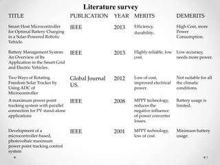
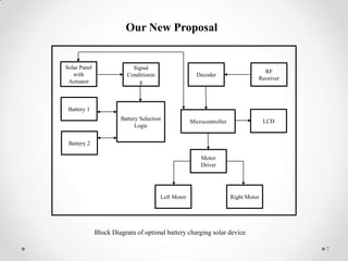
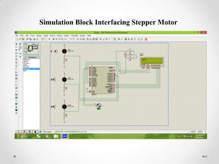
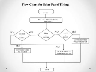

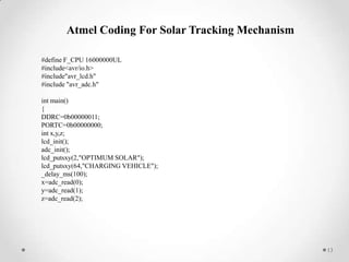


This document describes a student project to simulate optimal battery charging for a solar-powered vehicle. The project aims to design a solar tracking mechanism to increase solar power collection and a battery switching system to independently charge one battery while the other powers the vehicle. The project involves literature reviews on related topics, proposing a system design using a microcontroller, simulating the solar tracking mechanism, developing code for tracking and battery switching, and scheduling the work over multiple phases.


![Intelligent_Battery_Management_System[1] Automobile_IR111.pptx](https://cdn.slidesharecdn.com/ss_thumbnails/intelligentbatterymanagementsystem1automobileir111-230605074054-e78f70f3-thumbnail.jpg?width=640&height=640&fit=bounds)


