SlideShare a Scribd company logo
Workshop literature
STILL
ELECTRONIC
DOCUMENTATION
SYSTEM
Electric forklift truck
RX50-10
RX50-13
RX50-15
RX50-16
5051 5053 5054 5055
164530 EN - 05/2011
first in intralogistics
Edition05/2011 Edition 03/2005
Version S Version 3
• Update of the entire book and standardization • Completely revised edition
of the RX-series workshop manuals • Generation 5 converteradded
Edition 08/2005
• Version 4
• Servo hydraulics has been added
164530 [EN]
Documentation
This workshop manual contains all the informa-
tion required to assist the trained service engi-
neers with all work, repairs and maintenance
on this truck. In addition, some of the compo-
nents have been deliberately excluded from this
workshop manual and are explained elsewhere
in order to ensure a clear overview. Changes at
short notice arepossible atanytimeand arecom-
municated via Service Information documents.
The additional documentation comprises work-
shop manuals, special documentation and oper-
ating circuit diagrams.
Workshop manuals
• Display elements - display
• FleetManager’"
Special documentation
• Error list
• Overview of truck software
• STILL Flasher
• Overview of consumables
• FEM 4.004 test log book
Operating circuit diagrams
• see the circuit diagram overview
Symbols Used
ThesignaltermsDanger,Warning, Caution,Note
and Environment note are used in this document
as hazard warnings or for unusual information
that requires special identification:
means that failure tocomply involves risk to life and/or
major damage toproperty canoccur.
A WARNING
means that failure to comply involves risk of serious
injuryand/ormajordamagetopropertycanoccur.
A CAUTION
means that failure to comply involves risk of material
damage or destruction.
164530 [EN] III
NOTE
means fhafparticu/arallenlion is drawn fo com-
binations o/technica/factors which may nol be
evident even toospecia/ist.
% ENVIRONMENT NOTE
Theinstructionslistedheremustbecomplied
withasotherwiseen ironmentaf damagemay
resuft.
Foryour safety,additional symbols arealso used.
Please heed the varioussymbols.
Changes and retrofitting
Warnings before making changes to the
truck
If the truck is used for work not listed in the
guidelines or truck-specific original operating
instructions and has tobe converted or retrofitted
accordingly, youshouldbeawareofthefollowing:
• Any structural modification can affect the
handling and stability of the truck, and can
result in accidents.
• Without authorisation from STILL, nochanges
that affect the stability, the load capacity and
the safety systems may be carried out.
• Operation of the truck without an overhead
guard at a lift height of over 1800 mm is
prohibited.
• It is prohibited to install and use restraint
systems that are not approved by STILL.
• It is prohibited to drill holes in the overhead
guard or to perform welding on it.
• When carrying out welding on other parts of
the truck, it is essential that the battery and
all connections to the electronic controls are
disconnected.
• Only for electric forklift trucks: It is prohibited
to drill holes in the area of the driver’s seat into
the battery hood because hydrogen can enter
through the bores into the driver’s cab.
IV 164530[EN]
CE conformity
WiththeCE declaration ofconformity, STILL con-
firms that the truck complies with the standards
and regulations valid at the time of marketing.
The CE conformity mark is shown on the name-
plate and indicates compliance with the above
regulations.
A subsequent structural change or addition tothe
truck can compromise safety, thus invalidating
the CE declaration of conformity. In thiscase,
a new CE declaration of conformity is essential
for the structural changes. The company that
was instructed by thetruck operating company to
carry out the change is responsible for issuing a
new CE declaration ofconformity.
The contractor of the operating company must
also fulfil the following prerequisites:
Construction documents, test documents
and assembly instructions associated with
the change must be archived and remain
accessible at all times.
• Check that the capacity rating plate, decal in-
formation, hazard warnings andthe operating
instructions are consistent with regard to the
changes and modify ifnecessary.
Thechangemust beprocessed by adesign office
that specialises in the area of industrial trucks.
The change must be planned, checked and
implemented in accordance with the standards
and directives valid at the time.
Working with spare parts
Warning regarding non-original parts
Original parts, attachments and accessories are
specially designed for this truck. We specifi-
cally draw your attention to the fact that parts,
attachments and accessories supplied by other
companies have not been tested and approved
by STILL.
A CAUTION
Installation and/or use ofsuchproducts may therefore
haveanegativeimpactonthedesignfeaturesofthe
truckandthusimpairactive and/orpassive driving
safety.
Werecommend thatyouobtain approvalfromthe
manufacturer and,ifnecessary, fromtherelevant
regulatory authorities beforeinstallingsuchparts.
STILLacceptsnoliabilityforanydamagecausedby
the use of non-original parts and accessories without
approval.
ÝÛóͧ³¾±´
164530 [EN] V
Working with electronic controls
Itisnotgenerallypermitted toopencontrols.
STILL’s liability and the warranty are no longer
applicableoncethesealhasbeendamaged.
In exceptional cases, personnel authorised by
STILL are allowed to open the controls.
VI 164530 [EN]
00 Product information
Safety instructions ................................................. 00- 1
Safety instructions Electrical system ..................................... 00- 1
Jacking upthefront ofthetruck ........................................ 00- 1
Jacking up the rear of the truck ......................................... 00- 2
Securingtheforkcarriage ............................................ 00- 3
11 Electrical motor
h/lOtOR ............................................................. 11- 1
General technical data ............................................... 11- 1
Electrical connections ............................................... 11- 2
Drive unit ......................................................... 11- 3
Traction motor rotor disassembly ....................................... 11- 4
Traction motor rotor assembly ......................................... 11- 5
Speed sensor ..................................................... 11- 7
6B17 pinsensor ................................................... 11- 7
6B17 sensor bearing ................................................ 11- 8
Removing thesensor bearing ..........................................................................................11-10
Installing the sensor bearing ............................................................................................ 11-11
Temperature sensor .................................................................................. 11-13
KTY84 temperature sensor..............................................................................................11-13
Forced ventilation ...................................................................................... 11-15
Forced ventilation at the pump motor Heavy dust guard...................................................11-15
22 Mechanical drive axle
Wheel drive ....................................................... 22- 1
Wheel hub removal ................................................. 22- 1
Installing the wheel hub .............................................. 22- 2
Power unit ........................................................ 22- 4
General technical data ............................................... 22- 4
power unit ........................................................ 22- 5
Power unit disassembly .............................................. 22- 5
Power unit installation ............................................... 22- 7
31 Chassis
Counterweight ..................................................... 31- 1
164530 [EN] VII
34 Driver’s compartment
Driver’s seat ....................................................... 34- 1
seatcontactswitch ................................................. 34- 1
Seatbelt lock switch ................................................. 34- 1
42 Steering system
Hydraulicsteering ................................................. 42- 1
General technical data ............................................... 42- 1
steering system .................................................... 42- 2
Steering — error detection ............................................ 42- 3
Steering motor ..................................................... 42- 3
steeringmotorremoval .............................................. 42- 4
Steering motor installation ............................................ 42- 5
Sprocketwithtriggerwheel ........................................... 42- 6
Steering unit ...................................................... 42- 8
diaphragm pressure switch ........................................... 42- 9
Priority valve .............................................................................................................. 42-10
Steering-angle-dependent performance-CSC..........................................................42-11
CSC —functional test................................................................................................42-12
3B28 steeringzero sensor .........................................................................................42-13
Steering angle sensor with sensor disc......................................................................42-14
Steering angle sensor................................................................................................42-15
Steering wheel withsteering column...........................................................42-17
steering column..........................................................................................................42-17
46 Wheels and tires
Complete wheel assembly .......................................... 46- 1
General technical data ............................................... 46- 1
Superelastic tyres .................................................. 46- 1
Wheel bearing ..................................................... 46- 3
General technical data ............................................... 46- 3
Wheel bearing —wheel hub ........................................... 46- 3
49 Brake system
Hydraulic service brake ............................................. 49- 1
General technical data ............................................... 49- 1
Replacing thebrake shoes ............................................ 49- 1
Checking theservice brake ........................................... 49- 4
VIII 164530 [EN]
Wheel brake cylinder ................................................ 49- 5
Main brake cylinder ................................................. 49- 6
Brake sensor 1B2 .................................................. 49- 7
Brake fluid switch ................................................... 49- 8
Parking brake ..................................................... 49- 9
Adjusting the parking brake ........................................... 49- 9
parking brake switch ..................................................................................................49-11
50 Operational controls
Single pedal ....................................................... 50- 1
Single-pedal accelerator ............................................. 50- 1
Twin-pedal ........................................................ 50- 5
Two-pedal accelerator ............................................... 50- 5
Operational controls ............................................... 50- 8
Hand lever ........................................................ 50- 8
joystick .......................................................... 50- 9
Joystick operation ......................................................................................................50-11
Fingertip .....................................................................................................................50-12
Axle assignment.........................................................................................................50-14
Depressurisingthehydraulics ....................................................................................50-17
Switch..........................................................................................................to-1s
emergency isolator switch..........................................................................................50-18
Emergency off switch in the joystick ...........................................................................50-18
Key switch ..................................................................................................................50-19
56 Indicator elements
operator control panel .............................................. 56- 1
keypad .......................................................... 56- 1
mini console ...................................................... 56- 3
Display ........................................................... 56- 7
Display andoperating element -control processor .......................... 56- 7
Programming mode ................................................. 56- 9
Password level 1 ........................................................................................................56-11
Password level 2 ........................................................................................................56-15
164530 [EN] ix
60 Electrical system /electronic system
General ........................................................... 60- 1
General technical data ............................................... 60- 1
Devicecodeandreadoptions ......................................... 60- 2
Overviewofelectricalcomponents ...................................... 60- 3
Electrical system ................................................... 60- 4
Switchingonprocedurefortheelectricalsystem ............................ 60- 5
Tractionmotortemperaturemonitoring ................................... 60- 8
Pump motortemperature monitoring .........................................................................60-10
Software compatibility...................................................................................................... 60-11
Parameter management............................................................................................60-13
Intermediate circuit ....................................................................................................60-14
Insulationtestingforelectrictrucks.............................................................................. 60-15
Component insulation testing........................................................................................... 60-17
Wlring..................................................................................................................60-20
CAN bus connections.................................................................................................60-20
Electrical installation...................................................................................60-21
Control unit (vo)..........................................................................................................60-21
Fuses.........................................................................................................................60-22
contactor....................................................................................................................60-23
Warning system..........................................................................................60-24
horn............................................................................................................................60-24
Additional electrical installations.................................................................60-25
Rear distributorplate (add-on) ...................................................................................60-25
Front distributor plate.................................................................................................60-26
Relay board................................................................................................................60-27
64 Electronic controls
Traction and working hydraulics control ............................... 64- 1
control computer ................................................... 64- 1
Removing andinstalling thecontrol processor ............................. 64- 2
pump regulator .................................................... 64- 4
Removingandinstallingthepumpactuator ................................ 64- 6
Converter ......................................................... so- 9
Converter ........................................................ 64- 9
Generation 3converter ..............................................................................................64-10
Generation5driveconverter....................................................................................... 64-11
164530 [EN]
Removing and installingthe converter .......................................................................64-13
Hydraulic controller.................................................................................... 64-16
Hydraulic control unit..................................................................................................64-16
69 Batteries and accessories
Traction battery .................................................... 69- 1
battery .......................................................... 69- 1
Batteryconnector .................................................. 69- 3
battery discharge indicator ............................................ 69- 4
rollerplatform ..................................................... 69- 6
70 Hydraulics
General ........................................................... 70- 1
General technical data ............................................... 70- 1
Operatingspeedsforlifting ........................................... 70- 2
Operating speeds tilt ................................................ 70- 2
Operating speeds for lowering ......................................... 70- 3
Forward tilt safety test ............................................... 70- 4
Lowering safety test ................................................. 70- 4
Safety checks of hose assembly ........................................ 70- 5
Basehydraulics ................................................... 70- 6
Hydraulic installation ................................................ 70- 6
hydraulic oil tank ................................................... 70- 7
Hydraulicoil ...................................................... 70- 8
Intakefilter ....................................................... 70- 9
breatherfilter ..............................................................................................................70-10
High-pressure filter.....................................................................................................70-11
Conical nipplefittings (CNF).......................................................................................70-12
Bolted joint..................................................................................................................70-12
71 Working hydraulics
Pumpassembly ................................................... 71- 1
General technical data ............................................... 71- 1
Pump unit ........................................................ 71- 2
electrical connections ............................................... 71- 3
Pump motor - speed sensor ........................................... 71- 3
Temperaturesensorpumpmotor ....................................... 71- 4
motor brush monitor ................................................. 71- 6
164530 [EN] xi
brushes .......................................................... 71- 8
Pump motor removal ................................................ 71- 9
Pump motor installation .............................................. 71- 9
hydraulic pump .................................................... 71-10
Hydraulic pump Removal and installation ................................. 71-11
Tilt cylinder ........................................................ 71-13
Mast tilt .......................................................... 71-13
Tiltcylinder Removal andinstallation .................................... 71-13
Changing the set of seals ............................................. 71-15
Connection screw joints .............................................. 71-17
Additional hydraulics ............................................... 71-18
Attachments ...................................................... 71-18
Clamp locking mechanism for hand levers ................................ 71-19
Hose line on mast .................................................. 71-19
76 Valves
Hand lever ........................................................ 76- 1
General technical data ............................................... 76- 1
Hand lever valve block ............................................... 76- 3
Removing and installing the valve block .................................. 76- 5
Directional control valve-arrangement ................................... 76- 7
Directional control valve -function ...................................... 76- 8
Hydraulic sensor ................................................... 76- 9
pressure regulator .................................................. 76-11
Servo hydraulics ................................................... 76-13
General technical data ............................................... 76-13
Servo hydraulics valve block .......................................... 76-14
Manual lowering ................................................... 76-15
Directional control valve block ......................................... 76-16
81 Mast
/l£tSt ............................................................. 81- 1
General technical data ............................................... 81- 1
Telescopicmast ................................................... 81- 2
NiHo lift mast ...................................................... 81- 3
triplex mast ....................................................... 81- 4
Mastremoval ..................................................... 81- 5
xii
Mastinstallation ...................................................
164530 [EN]
81- 7
Chains ........................................................... 81- 8
Load chains Checking, cleaning ........................................ 81- 8
Adjusting the load chains Telescopic mast ................................ 81- 9
Adjusting the load chains NiHo lift mast............................................................................81-11
Outer loadchain Triple mast.............................................................................................81-13
Middle load chain Triple mast ...........................................................................................81-15
End position damping ................................................................................ 81-18
End position damping ofouter cylinder ............................................................................81-18
Middle cylinder end dampener .........................................................................................81-19
Hose safety valve ...............................................................................................81-20
Hose safety valve of triplex mast ......................................................................................81-20
Shock valve installation positions ....................................................................................81-20
Lift cylinder..........................................................................................................81-22
Lift jack.............................................................................................................................81-22
Centre cylinder .................................................................................................................81-22
Outer cylinder...................................................................................................................81-23
Rollers /supporting rollers ......................................................................... 81-26
Removing and installing thesupport rollers......................................................................81-26
84 Load carrier
Annex
X Circuit diagrams
Hydraulics X- 1
Hand lever ......................................................... X- 1
Servo hydraulics .................................................... X- 3
164530 [EN] XIII
Fork carriage ...................................................... 84- 1
Roller ........................................................... 84- 2
BUY NOW
Instant Download the
CompleteManual

More Related Content

Similar to SMBITStillRx50-10.pdf

Similar to SMBITStillRx50-10.pdf (7)

Nissan forklift p frame - psl series service repair manual
Nissan forklift p frame - psl series service repair manualNissan forklift p frame - psl series service repair manual
Nissan forklift p frame - psl series service repair manual
 
Nissan forklift p frame - pll series service repair manual
Nissan forklift p frame - pll series service repair manualNissan forklift p frame - pll series service repair manual
Nissan forklift p frame - pll series service repair manual
 
Nissan forklift p frame - psd series service repair manual
Nissan forklift p frame - psd series service repair manualNissan forklift p frame - psd series service repair manual
Nissan forklift p frame - psd series service repair manual
 
Nissan forklift p frame - pll series service repair manual
Nissan forklift p frame - pll series service repair manualNissan forklift p frame - pll series service repair manual
Nissan forklift p frame - pll series service repair manual
 
BOBCAT 425 COMPACT EXCAVATOR Service Repair Manual SN A9K311001 & Above.pdf
BOBCAT 425 COMPACT EXCAVATOR Service Repair Manual SN A9K311001 & Above.pdfBOBCAT 425 COMPACT EXCAVATOR Service Repair Manual SN A9K311001 & Above.pdf
BOBCAT 425 COMPACT EXCAVATOR Service Repair Manual SN A9K311001 & Above.pdf
 
BOBCAT 428 COMPACT EXCAVATOR Service Repair Manual SN A9K411001 & Above.pdf
BOBCAT 428 COMPACT EXCAVATOR Service Repair Manual SN A9K411001 & Above.pdfBOBCAT 428 COMPACT EXCAVATOR Service Repair Manual SN A9K411001 & Above.pdf
BOBCAT 428 COMPACT EXCAVATOR Service Repair Manual SN A9K411001 & Above.pdf
 
BOBCAT 428 COMPACT EXCAVATOR Service Repair Manual SN A9K411001 & Above.pdf
BOBCAT 428 COMPACT EXCAVATOR Service Repair Manual SN A9K411001 & Above.pdfBOBCAT 428 COMPACT EXCAVATOR Service Repair Manual SN A9K411001 & Above.pdf
BOBCAT 428 COMPACT EXCAVATOR Service Repair Manual SN A9K411001 & Above.pdf
 

Recently uploaded

一比一原版SDSU毕业证圣地亚哥州立大学毕业证成绩单如何办理
一比一原版SDSU毕业证圣地亚哥州立大学毕业证成绩单如何办理一比一原版SDSU毕业证圣地亚哥州立大学毕业证成绩单如何办理
一比一原版SDSU毕业证圣地亚哥州立大学毕业证成绩单如何办理
psavhef
 
The Future of Autonomous Vehicles | civilthings.com | Detailed information
The Future of Autonomous Vehicles | civilthings.com |  Detailed informationThe Future of Autonomous Vehicles | civilthings.com |  Detailed information
The Future of Autonomous Vehicles | civilthings.com | Detailed information
gettygaming1
 
一比一原版BC毕业证波士顿学院毕业证成绩单如何办理
一比一原版BC毕业证波士顿学院毕业证成绩单如何办理一比一原版BC毕业证波士顿学院毕业证成绩单如何办理
一比一原版BC毕业证波士顿学院毕业证成绩单如何办理
amvovau
 

Recently uploaded (8)

Understanding BDA and BBMP: Key Players in Bangalore’s Urban Development
Understanding BDA and BBMP: Key Players in Bangalore’s Urban DevelopmentUnderstanding BDA and BBMP: Key Players in Bangalore’s Urban Development
Understanding BDA and BBMP: Key Players in Bangalore’s Urban Development
 
一比一原版SDSU毕业证圣地亚哥州立大学毕业证成绩单如何办理
一比一原版SDSU毕业证圣地亚哥州立大学毕业证成绩单如何办理一比一原版SDSU毕业证圣地亚哥州立大学毕业证成绩单如何办理
一比一原版SDSU毕业证圣地亚哥州立大学毕业证成绩单如何办理
 
The Future of Autonomous Vehicles | civilthings.com | Detailed information
The Future of Autonomous Vehicles | civilthings.com |  Detailed informationThe Future of Autonomous Vehicles | civilthings.com |  Detailed information
The Future of Autonomous Vehicles | civilthings.com | Detailed information
 
Advanced Technology for Auto Part Industry Inventory Solutions
Advanced Technology for Auto Part Industry Inventory SolutionsAdvanced Technology for Auto Part Industry Inventory Solutions
Advanced Technology for Auto Part Industry Inventory Solutions
 
一比一原版BC毕业证波士顿学院毕业证成绩单如何办理
一比一原版BC毕业证波士顿学院毕业证成绩单如何办理一比一原版BC毕业证波士顿学院毕业证成绩单如何办理
一比一原版BC毕业证波士顿学院毕业证成绩单如何办理
 
gtyccccccccccccccccccccccccccccccccccccccccccccccccccccccc
gtycccccccccccccccccccccccccccccccccccccccccccccccccccccccgtyccccccccccccccccccccccccccccccccccccccccccccccccccccccc
gtyccccccccccccccccccccccccccccccccccccccccccccccccccccccc
 
Core technology of Hyundai Motor Group's EV platform 'E-GMP'
Core technology of Hyundai Motor Group's EV platform 'E-GMP'Core technology of Hyundai Motor Group's EV platform 'E-GMP'
Core technology of Hyundai Motor Group's EV platform 'E-GMP'
 
Essential Maintenance Tips For Commercial Vans.
Essential Maintenance Tips For Commercial Vans.Essential Maintenance Tips For Commercial Vans.
Essential Maintenance Tips For Commercial Vans.
 

SMBITStillRx50-10.pdf

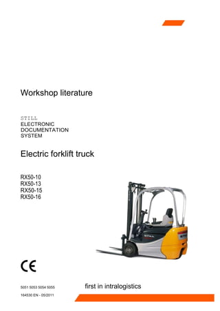
  • 1. Workshop literature STILL ELECTRONIC DOCUMENTATION SYSTEM Electric forklift truck RX50-10 RX50-13 RX50-15 RX50-16 5051 5053 5054 5055 164530 EN - 05/2011 first in intralogistics
  • 2.
  • 3. Edition05/2011 Edition 03/2005 Version S Version 3 • Update of the entire book and standardization • Completely revised edition of the RX-series workshop manuals • Generation 5 converteradded Edition 08/2005 • Version 4 • Servo hydraulics has been added 164530 [EN]
  • 4.
  • 5. Documentation This workshop manual contains all the informa- tion required to assist the trained service engi- neers with all work, repairs and maintenance on this truck. In addition, some of the compo- nents have been deliberately excluded from this workshop manual and are explained elsewhere in order to ensure a clear overview. Changes at short notice arepossible atanytimeand arecom- municated via Service Information documents. The additional documentation comprises work- shop manuals, special documentation and oper- ating circuit diagrams. Workshop manuals • Display elements - display • FleetManager’" Special documentation • Error list • Overview of truck software • STILL Flasher • Overview of consumables • FEM 4.004 test log book Operating circuit diagrams • see the circuit diagram overview Symbols Used ThesignaltermsDanger,Warning, Caution,Note and Environment note are used in this document as hazard warnings or for unusual information that requires special identification: means that failure tocomply involves risk to life and/or major damage toproperty canoccur. A WARNING means that failure to comply involves risk of serious injuryand/ormajordamagetopropertycanoccur. A CAUTION means that failure to comply involves risk of material damage or destruction. 164530 [EN] III
  • 6. NOTE means fhafparticu/arallenlion is drawn fo com- binations o/technica/factors which may nol be evident even toospecia/ist. % ENVIRONMENT NOTE Theinstructionslistedheremustbecomplied withasotherwiseen ironmentaf damagemay resuft. Foryour safety,additional symbols arealso used. Please heed the varioussymbols. Changes and retrofitting Warnings before making changes to the truck If the truck is used for work not listed in the guidelines or truck-specific original operating instructions and has tobe converted or retrofitted accordingly, youshouldbeawareofthefollowing: • Any structural modification can affect the handling and stability of the truck, and can result in accidents. • Without authorisation from STILL, nochanges that affect the stability, the load capacity and the safety systems may be carried out. • Operation of the truck without an overhead guard at a lift height of over 1800 mm is prohibited. • It is prohibited to install and use restraint systems that are not approved by STILL. • It is prohibited to drill holes in the overhead guard or to perform welding on it. • When carrying out welding on other parts of the truck, it is essential that the battery and all connections to the electronic controls are disconnected. • Only for electric forklift trucks: It is prohibited to drill holes in the area of the driver’s seat into the battery hood because hydrogen can enter through the bores into the driver’s cab. IV 164530[EN]
  • 7. CE conformity WiththeCE declaration ofconformity, STILL con- firms that the truck complies with the standards and regulations valid at the time of marketing. The CE conformity mark is shown on the name- plate and indicates compliance with the above regulations. A subsequent structural change or addition tothe truck can compromise safety, thus invalidating the CE declaration of conformity. In thiscase, a new CE declaration of conformity is essential for the structural changes. The company that was instructed by thetruck operating company to carry out the change is responsible for issuing a new CE declaration ofconformity. The contractor of the operating company must also fulfil the following prerequisites: Construction documents, test documents and assembly instructions associated with the change must be archived and remain accessible at all times. • Check that the capacity rating plate, decal in- formation, hazard warnings andthe operating instructions are consistent with regard to the changes and modify ifnecessary. Thechangemust beprocessed by adesign office that specialises in the area of industrial trucks. The change must be planned, checked and implemented in accordance with the standards and directives valid at the time. Working with spare parts Warning regarding non-original parts Original parts, attachments and accessories are specially designed for this truck. We specifi- cally draw your attention to the fact that parts, attachments and accessories supplied by other companies have not been tested and approved by STILL. A CAUTION Installation and/or use ofsuchproducts may therefore haveanegativeimpactonthedesignfeaturesofthe truckandthusimpairactive and/orpassive driving safety. Werecommend thatyouobtain approvalfromthe manufacturer and,ifnecessary, fromtherelevant regulatory authorities beforeinstallingsuchparts. STILLacceptsnoliabilityforanydamagecausedby the use of non-original parts and accessories without approval. ÝÛóͧ³¾±´ 164530 [EN] V
  • 8. Working with electronic controls Itisnotgenerallypermitted toopencontrols. STILL’s liability and the warranty are no longer applicableoncethesealhasbeendamaged. In exceptional cases, personnel authorised by STILL are allowed to open the controls. VI 164530 [EN]
  • 9. 00 Product information Safety instructions ................................................. 00- 1 Safety instructions Electrical system ..................................... 00- 1 Jacking upthefront ofthetruck ........................................ 00- 1 Jacking up the rear of the truck ......................................... 00- 2 Securingtheforkcarriage ............................................ 00- 3 11 Electrical motor h/lOtOR ............................................................. 11- 1 General technical data ............................................... 11- 1 Electrical connections ............................................... 11- 2 Drive unit ......................................................... 11- 3 Traction motor rotor disassembly ....................................... 11- 4 Traction motor rotor assembly ......................................... 11- 5 Speed sensor ..................................................... 11- 7 6B17 pinsensor ................................................... 11- 7 6B17 sensor bearing ................................................ 11- 8 Removing thesensor bearing ..........................................................................................11-10 Installing the sensor bearing ............................................................................................ 11-11 Temperature sensor .................................................................................. 11-13 KTY84 temperature sensor..............................................................................................11-13 Forced ventilation ...................................................................................... 11-15 Forced ventilation at the pump motor Heavy dust guard...................................................11-15 22 Mechanical drive axle Wheel drive ....................................................... 22- 1 Wheel hub removal ................................................. 22- 1 Installing the wheel hub .............................................. 22- 2 Power unit ........................................................ 22- 4 General technical data ............................................... 22- 4 power unit ........................................................ 22- 5 Power unit disassembly .............................................. 22- 5 Power unit installation ............................................... 22- 7 31 Chassis Counterweight ..................................................... 31- 1 Counterweight ..................................................... 31- 1 164530 [EN] VII
  • 10. 34 Driver’s compartment Driver’s seat ....................................................... 34- 1 seatcontactswitch ................................................. 34- 1 Seatbelt lock switch ................................................. 34- 1 42 Steering system Hydraulicsteering ................................................. 42- 1 General technical data ............................................... 42- 1 steering system .................................................... 42- 2 Steering — error detection ............................................ 42- 3 Steering motor ..................................................... 42- 3 steeringmotorremoval .............................................. 42- 4 Steering motor installation ............................................ 42- 5 Sprocketwithtriggerwheel ........................................... 42- 6 Steering unit ...................................................... 42- 8 diaphragm pressure switch ........................................... 42- 9 Priority valve .............................................................................................................. 42-10 Steering-angle-dependent performance-CSC..........................................................42-11 CSC —functional test................................................................................................42-12 3B28 steeringzero sensor .........................................................................................42-13 Steering angle sensor with sensor disc......................................................................42-14 Steering angle sensor................................................................................................42-15 Steering wheel withsteering column...........................................................42-17 steering column..........................................................................................................42-17 46 Wheels and tires Complete wheel assembly .......................................... 46- 1 General technical data ............................................... 46- 1 Superelastic tyres .................................................. 46- 1 Wheel bearing ..................................................... 46- 3 General technical data ............................................... 46- 3 Wheel bearing —wheel hub ........................................... 46- 3 49 Brake system Hydraulic service brake ............................................. 49- 1 General technical data ............................................... 49- 1 Replacing thebrake shoes ............................................ 49- 1 Checking theservice brake ........................................... 49- 4 VIII 164530 [EN]
  • 11. Wheel brake cylinder ................................................ 49- 5 Main brake cylinder ................................................. 49- 6 Brake sensor 1B2 .................................................. 49- 7 Brake fluid switch ................................................... 49- 8 Parking brake ..................................................... 49- 9 Adjusting the parking brake ........................................... 49- 9 parking brake switch ..................................................................................................49-11 50 Operational controls Single pedal ....................................................... 50- 1 Single-pedal accelerator ............................................. 50- 1 Twin-pedal ........................................................ 50- 5 Two-pedal accelerator ............................................... 50- 5 Operational controls ............................................... 50- 8 Hand lever ........................................................ 50- 8 joystick .......................................................... 50- 9 Joystick operation ......................................................................................................50-11 Fingertip .....................................................................................................................50-12 Axle assignment.........................................................................................................50-14 Depressurisingthehydraulics ....................................................................................50-17 Switch..........................................................................................................to-1s emergency isolator switch..........................................................................................50-18 Emergency off switch in the joystick ...........................................................................50-18 Key switch ..................................................................................................................50-19 56 Indicator elements operator control panel .............................................. 56- 1 keypad .......................................................... 56- 1 mini console ...................................................... 56- 3 Display ........................................................... 56- 7 Display andoperating element -control processor .......................... 56- 7 Programming mode ................................................. 56- 9 Password level 1 ........................................................................................................56-11 Password level 2 ........................................................................................................56-15 164530 [EN] ix
  • 12. 60 Electrical system /electronic system General ........................................................... 60- 1 General technical data ............................................... 60- 1 Devicecodeandreadoptions ......................................... 60- 2 Overviewofelectricalcomponents ...................................... 60- 3 Electrical system ................................................... 60- 4 Switchingonprocedurefortheelectricalsystem ............................ 60- 5 Tractionmotortemperaturemonitoring ................................... 60- 8 Pump motortemperature monitoring .........................................................................60-10 Software compatibility...................................................................................................... 60-11 Parameter management............................................................................................60-13 Intermediate circuit ....................................................................................................60-14 Insulationtestingforelectrictrucks.............................................................................. 60-15 Component insulation testing........................................................................................... 60-17 Wlring..................................................................................................................60-20 CAN bus connections.................................................................................................60-20 Electrical installation...................................................................................60-21 Control unit (vo)..........................................................................................................60-21 Fuses.........................................................................................................................60-22 contactor....................................................................................................................60-23 Warning system..........................................................................................60-24 horn............................................................................................................................60-24 Additional electrical installations.................................................................60-25 Rear distributorplate (add-on) ...................................................................................60-25 Front distributor plate.................................................................................................60-26 Relay board................................................................................................................60-27 64 Electronic controls Traction and working hydraulics control ............................... 64- 1 control computer ................................................... 64- 1 Removing andinstalling thecontrol processor ............................. 64- 2 pump regulator .................................................... 64- 4 Removingandinstallingthepumpactuator ................................ 64- 6 Converter ......................................................... so- 9 Converter ........................................................ 64- 9 Generation 3converter ..............................................................................................64-10 Generation5driveconverter....................................................................................... 64-11 164530 [EN]
  • 13. Removing and installingthe converter .......................................................................64-13 Hydraulic controller.................................................................................... 64-16 Hydraulic control unit..................................................................................................64-16 69 Batteries and accessories Traction battery .................................................... 69- 1 battery .......................................................... 69- 1 Batteryconnector .................................................. 69- 3 battery discharge indicator ............................................ 69- 4 rollerplatform ..................................................... 69- 6 70 Hydraulics General ........................................................... 70- 1 General technical data ............................................... 70- 1 Operatingspeedsforlifting ........................................... 70- 2 Operating speeds tilt ................................................ 70- 2 Operating speeds for lowering ......................................... 70- 3 Forward tilt safety test ............................................... 70- 4 Lowering safety test ................................................. 70- 4 Safety checks of hose assembly ........................................ 70- 5 Basehydraulics ................................................... 70- 6 Hydraulic installation ................................................ 70- 6 hydraulic oil tank ................................................... 70- 7 Hydraulicoil ...................................................... 70- 8 Intakefilter ....................................................... 70- 9 breatherfilter ..............................................................................................................70-10 High-pressure filter.....................................................................................................70-11 Conical nipplefittings (CNF).......................................................................................70-12 Bolted joint..................................................................................................................70-12 71 Working hydraulics Pumpassembly ................................................... 71- 1 General technical data ............................................... 71- 1 Pump unit ........................................................ 71- 2 electrical connections ............................................... 71- 3 Pump motor - speed sensor ........................................... 71- 3 Temperaturesensorpumpmotor ....................................... 71- 4 motor brush monitor ................................................. 71- 6 164530 [EN] xi
  • 14. brushes .......................................................... 71- 8 Pump motor removal ................................................ 71- 9 Pump motor installation .............................................. 71- 9 hydraulic pump .................................................... 71-10 Hydraulic pump Removal and installation ................................. 71-11 Tilt cylinder ........................................................ 71-13 Mast tilt .......................................................... 71-13 Tiltcylinder Removal andinstallation .................................... 71-13 Changing the set of seals ............................................. 71-15 Connection screw joints .............................................. 71-17 Additional hydraulics ............................................... 71-18 Attachments ...................................................... 71-18 Clamp locking mechanism for hand levers ................................ 71-19 Hose line on mast .................................................. 71-19 76 Valves Hand lever ........................................................ 76- 1 General technical data ............................................... 76- 1 Hand lever valve block ............................................... 76- 3 Removing and installing the valve block .................................. 76- 5 Directional control valve-arrangement ................................... 76- 7 Directional control valve -function ...................................... 76- 8 Hydraulic sensor ................................................... 76- 9 pressure regulator .................................................. 76-11 Servo hydraulics ................................................... 76-13 General technical data ............................................... 76-13 Servo hydraulics valve block .......................................... 76-14 Manual lowering ................................................... 76-15 Directional control valve block ......................................... 76-16 81 Mast /l£tSt ............................................................. 81- 1 General technical data ............................................... 81- 1 Telescopicmast ................................................... 81- 2 NiHo lift mast ...................................................... 81- 3 triplex mast ....................................................... 81- 4 Mastremoval ..................................................... 81- 5 xii Mastinstallation ................................................... 164530 [EN] 81- 7
  • 15. Chains ........................................................... 81- 8 Load chains Checking, cleaning ........................................ 81- 8 Adjusting the load chains Telescopic mast ................................ 81- 9 Adjusting the load chains NiHo lift mast............................................................................81-11 Outer loadchain Triple mast.............................................................................................81-13 Middle load chain Triple mast ...........................................................................................81-15 End position damping ................................................................................ 81-18 End position damping ofouter cylinder ............................................................................81-18 Middle cylinder end dampener .........................................................................................81-19 Hose safety valve ...............................................................................................81-20 Hose safety valve of triplex mast ......................................................................................81-20 Shock valve installation positions ....................................................................................81-20 Lift cylinder..........................................................................................................81-22 Lift jack.............................................................................................................................81-22 Centre cylinder .................................................................................................................81-22 Outer cylinder...................................................................................................................81-23 Rollers /supporting rollers ......................................................................... 81-26 Removing and installing thesupport rollers......................................................................81-26 84 Load carrier Annex X Circuit diagrams Hydraulics X- 1 Hand lever ......................................................... X- 1 Servo hydraulics .................................................... X- 3 164530 [EN] XIII Fork carriage ...................................................... 84- 1 Fork carriage ...................................................... 84- 1 Roller ........................................................... 84- 2
  • 16. BUY NOW Instant Download the CompleteManual