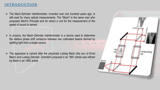
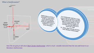
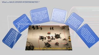
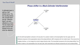
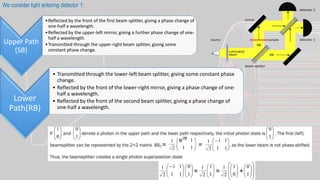
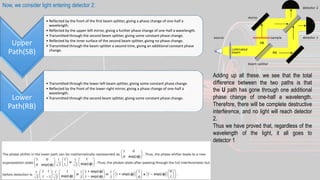
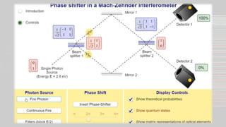
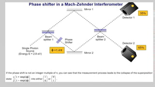
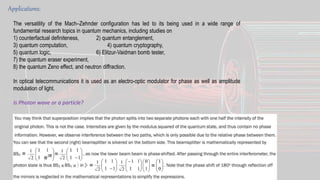
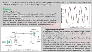
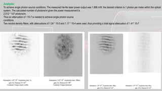
Ajay Boro
Sukhjovan Singh Gill
Supriya Pan
Single Photon Mach Zehnder
Interferometer
I N TRO D UCTIO N
 The Mach-Zehnder interferometer, invented over one hundred years ago, is
still used for many optical measurements. The "Mach" is the same man who
proposed Mach's Principle and for whom a unit for the measurement of the
speed of sound is named
 In physics, the Mach–Zehnder interferometer is a device used to determine
the relative phase shift variations between two collimated beams derived by
splitting light from a single source.
 The apparatus is named after the physicists Ludwig Mach (the son of Ernst
Mach) and Ludwig Zehnder. Zehnder's proposal in an 1891 article was refined
by Mach in an 1892 article
What is Interferometer?
Here We are going to talk about Mach Zender Interferometer which is much versatile instrument than the very well known to us
Michelson interferometer.
What's a MACK ZENDER INTERFEROMETER ?
Important Facts To Know:
 The "half-silvered" mirror only reflects half the light incident on it,
refracting the other half through it, also called a beam splitter.
 When a ray is incident on a surface and the material on the other side
of the surface has a higher index of refraction then the reflected light
ray is shifted in its phase by exactly one half a wavelength.
 So, light reflected by a mirror has its phase changed by one half a
wavelength.
 When a light ray is incident on a surface and the material on the other
side of the surface has a lower refractive index, the reflected light ray
does not have its phase changed.
 When a light ray goes from one medium into another, its direction
changes due to refraction but no phase change occurs at the surfaces
of the two mediums.
 When a light ray travels through a medium, such as a glass plate, its
phase will be shifted by an amount that depends on the index of
refraction of the medium and the path length of the light ray through
the medium.
Some Basics Of SPFE (Single Photon Faraday Effect):
The classical Faraday
effect is a linear
magneto-optic effect,
which is characterized by
a rotation of the linear
polarization of light
propagating inside an
isotropic medium subject
to an external constant
magnetic field applied in
the direction of
propagation.
The general concept
behind the Faraday effect
is that a linearly polarized
wave can be decomposed
into two circularly
polarized waves, which
are the appropriate
normal modes in this
regime; each circularly
polarized normal mode
propagates with different
refractive indices.
Quantum mechanics tells
us that the magnetic field
induced splitting of the
energy levels with
different total angular
momenta is the reason
for the linear polarization
rotation, and hence the
different circular
polarizations of light
couple differently during
the process of virtual
absorption, which is
responsible for the
existence of refractive
indices.
Similarly, the SPFE
involves the rotation of
linearly polarized light as
a result of broken
symmetry between the
left and right
components of circularly
polarized light.
However, the SPFE only
involves the no resonant
interaction of a single
photon with a two-level
system, does not require an
external magnetic field, and
can result magnetic field
exploited in the classical
case. The ensuing rotation
of the polarization is a
consequence of one
circular polarization, say
RCP, interacting with only
the heavy hole band and
the LCP with the light hole
band as depicted in Fig.
How is the M-Z Interferometer Setup?
We allow single photons to pass through and Mach-Zehnder interferometer, as diagrammed in above figure
How Does It Work?
A collimated beam is
split by a half-
silvered mirror. The
two resulting beams
(the "sample beam"
and the "reference
beam") are each
reflected by a mirror.
The two beams then
pass a second half-
silvered mirror and
enter two detectors
Upper Path
(SB)
•Reflected by the front of the first beam splitter, giving a phase change of
one-half a wavelength.
•Reflected by the upper-left mirror, giving a further phase change of one-
half a wavelength.
•Transmitted through the upper-right beam splitter, giving some
constant phase change.
Lower
Path(RB)
• Transmitted through the lower-left beam splitter, giving some constant phase
change.
• Reflected by the front of the lower-right mirror, giving a phase change of one-
half a wavelength.
• Reflected by the front of the second beam splitter, giving a phase change of
one-half a wavelength.
We consider light entering detector 1:
Upper
Path(SB)
• Reflected by the front of the first beam splitter, giving a phase change of one-half a
wavelength.
• Reflected by the upper-left mirror, giving a further phase change of one-half a wavelength.
• Transmitted through the second beam splitter, giving some constant phase change.
• Reflected by the inner surface of the second beam splitter, giving no phase change.
• Transmitted through the beam splitter a second time, giving an additional constant phase
change.
Lower
Path(RB)
• Transmitted through the lower-left beam splitter, giving some constant phase change.
• Reflected by the front of the lower-right mirror, giving a phase change of one-half a
wavelength.
• Transmitted through the second beam splitter, giving some constant phase change.
Now, we consider light entering detector 2:
Adding up all these, we see that the total
difference between the two paths is that
the U path has gone through one additional
phase change of one-half a wavelength.
Therefore, there will be complete destructive
interference, and no light will reach detector
2.
Thus we have proved that, regardless of the
wavelength of the light, it all goes to
detector 1
Applications:
The versatility of the Mach–Zehnder configuration has led to its being used in a wide range of
fundamental research topics in quantum mechanics, including studies on
1) counterfactual definiteness, 2) quantum entanglement,
3) quantum computation, 4) quantum cryptography,
5) quantum logic, 6) Elitzur-Vaidman bomb tester,
7) the quantum eraser experiment,
8) the quantum Zeno effect, and neutron diffraction.
In optical telecommunications it is used as an electro-optic modulator for phase as well as amplitude
modulation of light.
Is Photon wave or a particle?
We can see how the wave nature of a photon is revealed through this experiment leads us to compromise on the information
of “Which Path” photon takes to reach detector 1(particle property).
Experiment:
 “Which Path” Puzzle
In this activity, you will experimentally observe the effect of “which-path”
information using a M-Z interferometer. The experiment is set-up as shown
in the schematic diagram
Now you know the polarization states of photons in both paths. Suppose
you had a device that measured polarization . If this device detected a
horizontal photon, you would know for sure that it came through path 1.
 Single Photon Interference
In the previous activity, we found that any attempt to get “which-
path” information destroys the wave nature of the photons and
therefore, the interference pattern.
Removal of any possibility of determining this information brings
the fringes back.
So, In this activity we will perform the experiment at the single
photon level. Obtaining similar results as before would confirm that
a single photon does, in fact, interfere with itself and the
interference fringes at high light level are just the combined effect of
many single-photon interference patterns (see the expt. Data above)
Analysis:
To achieve single photon source conditions, The measured He-Ne laser power output was 1.896 mW. the desired criterion is 1 photon per meter within the optical
system. The calculated number of photons/m given the power measurement is
2.012 * 107 photons/m.
Thus an attenuation of ~10-7 is needed to achieve single photon source
conditions.
Two neutral density filters, with attenuations of 1.24 * 10-3 and 1.17 * 10-4 were used, thus providing a total signal attenuation of 1.41* 10-7
Bibliography:
 https://en.wikipedia.org/wiki/Mach%E2%80%93Zehnder_interferometer
 https://www.st-
andrews.ac.uk/physics/quvis/simulations_html5/sims/Mach_Zehnder_PhaseShifte
r/Mach_Zehnder_PhaseShifter.html
 https://faraday.physics.utoronto.ca/GeneralInterest/Harrison/MachZehnder/Mach
Zehnder.html
 http://iopscience.iop.org/article/10.1088/0143-0807/37/2/024001
THANKS TO DILIP Pal Sir

Single photon Mach zender interferometer

  • 1.
    Ajay Boro Sukhjovan SinghGill Supriya Pan Single Photon Mach Zehnder Interferometer
  • 2.
    I N TROD UCTIO N  The Mach-Zehnder interferometer, invented over one hundred years ago, is still used for many optical measurements. The "Mach" is the same man who proposed Mach's Principle and for whom a unit for the measurement of the speed of sound is named  In physics, the Mach–Zehnder interferometer is a device used to determine the relative phase shift variations between two collimated beams derived by splitting light from a single source.  The apparatus is named after the physicists Ludwig Mach (the son of Ernst Mach) and Ludwig Zehnder. Zehnder's proposal in an 1891 article was refined by Mach in an 1892 article
  • 3.
    What is Interferometer? HereWe are going to talk about Mach Zender Interferometer which is much versatile instrument than the very well known to us Michelson interferometer.
  • 4.
    What's a MACKZENDER INTERFEROMETER ?
  • 5.
    Important Facts ToKnow:  The "half-silvered" mirror only reflects half the light incident on it, refracting the other half through it, also called a beam splitter.  When a ray is incident on a surface and the material on the other side of the surface has a higher index of refraction then the reflected light ray is shifted in its phase by exactly one half a wavelength.  So, light reflected by a mirror has its phase changed by one half a wavelength.  When a light ray is incident on a surface and the material on the other side of the surface has a lower refractive index, the reflected light ray does not have its phase changed.  When a light ray goes from one medium into another, its direction changes due to refraction but no phase change occurs at the surfaces of the two mediums.  When a light ray travels through a medium, such as a glass plate, its phase will be shifted by an amount that depends on the index of refraction of the medium and the path length of the light ray through the medium.
  • 6.
    Some Basics OfSPFE (Single Photon Faraday Effect): The classical Faraday effect is a linear magneto-optic effect, which is characterized by a rotation of the linear polarization of light propagating inside an isotropic medium subject to an external constant magnetic field applied in the direction of propagation. The general concept behind the Faraday effect is that a linearly polarized wave can be decomposed into two circularly polarized waves, which are the appropriate normal modes in this regime; each circularly polarized normal mode propagates with different refractive indices. Quantum mechanics tells us that the magnetic field induced splitting of the energy levels with different total angular momenta is the reason for the linear polarization rotation, and hence the different circular polarizations of light couple differently during the process of virtual absorption, which is responsible for the existence of refractive indices. Similarly, the SPFE involves the rotation of linearly polarized light as a result of broken symmetry between the left and right components of circularly polarized light. However, the SPFE only involves the no resonant interaction of a single photon with a two-level system, does not require an external magnetic field, and can result magnetic field exploited in the classical case. The ensuing rotation of the polarization is a consequence of one circular polarization, say RCP, interacting with only the heavy hole band and the LCP with the light hole band as depicted in Fig.
  • 7.
    How is theM-Z Interferometer Setup? We allow single photons to pass through and Mach-Zehnder interferometer, as diagrammed in above figure
  • 8.
    How Does ItWork? A collimated beam is split by a half- silvered mirror. The two resulting beams (the "sample beam" and the "reference beam") are each reflected by a mirror. The two beams then pass a second half- silvered mirror and enter two detectors
  • 9.
    Upper Path (SB) •Reflected bythe front of the first beam splitter, giving a phase change of one-half a wavelength. •Reflected by the upper-left mirror, giving a further phase change of one- half a wavelength. •Transmitted through the upper-right beam splitter, giving some constant phase change. Lower Path(RB) • Transmitted through the lower-left beam splitter, giving some constant phase change. • Reflected by the front of the lower-right mirror, giving a phase change of one- half a wavelength. • Reflected by the front of the second beam splitter, giving a phase change of one-half a wavelength. We consider light entering detector 1:
  • 10.
    Upper Path(SB) • Reflected bythe front of the first beam splitter, giving a phase change of one-half a wavelength. • Reflected by the upper-left mirror, giving a further phase change of one-half a wavelength. • Transmitted through the second beam splitter, giving some constant phase change. • Reflected by the inner surface of the second beam splitter, giving no phase change. • Transmitted through the beam splitter a second time, giving an additional constant phase change. Lower Path(RB) • Transmitted through the lower-left beam splitter, giving some constant phase change. • Reflected by the front of the lower-right mirror, giving a phase change of one-half a wavelength. • Transmitted through the second beam splitter, giving some constant phase change. Now, we consider light entering detector 2: Adding up all these, we see that the total difference between the two paths is that the U path has gone through one additional phase change of one-half a wavelength. Therefore, there will be complete destructive interference, and no light will reach detector 2. Thus we have proved that, regardless of the wavelength of the light, it all goes to detector 1
  • 13.
    Applications: The versatility ofthe Mach–Zehnder configuration has led to its being used in a wide range of fundamental research topics in quantum mechanics, including studies on 1) counterfactual definiteness, 2) quantum entanglement, 3) quantum computation, 4) quantum cryptography, 5) quantum logic, 6) Elitzur-Vaidman bomb tester, 7) the quantum eraser experiment, 8) the quantum Zeno effect, and neutron diffraction. In optical telecommunications it is used as an electro-optic modulator for phase as well as amplitude modulation of light. Is Photon wave or a particle?
  • 14.
    We can seehow the wave nature of a photon is revealed through this experiment leads us to compromise on the information of “Which Path” photon takes to reach detector 1(particle property). Experiment:  “Which Path” Puzzle In this activity, you will experimentally observe the effect of “which-path” information using a M-Z interferometer. The experiment is set-up as shown in the schematic diagram Now you know the polarization states of photons in both paths. Suppose you had a device that measured polarization . If this device detected a horizontal photon, you would know for sure that it came through path 1.  Single Photon Interference In the previous activity, we found that any attempt to get “which- path” information destroys the wave nature of the photons and therefore, the interference pattern. Removal of any possibility of determining this information brings the fringes back. So, In this activity we will perform the experiment at the single photon level. Obtaining similar results as before would confirm that a single photon does, in fact, interfere with itself and the interference fringes at high light level are just the combined effect of many single-photon interference patterns (see the expt. Data above)
  • 15.
    Analysis: To achieve singlephoton source conditions, The measured He-Ne laser power output was 1.896 mW. the desired criterion is 1 photon per meter within the optical system. The calculated number of photons/m given the power measurement is 2.012 * 107 photons/m. Thus an attenuation of ~10-7 is needed to achieve single photon source conditions. Two neutral density filters, with attenuations of 1.24 * 10-3 and 1.17 * 10-4 were used, thus providing a total signal attenuation of 1.41* 10-7
  • 16.
    Bibliography:  https://en.wikipedia.org/wiki/Mach%E2%80%93Zehnder_interferometer  https://www.st- andrews.ac.uk/physics/quvis/simulations_html5/sims/Mach_Zehnder_PhaseShifte r/Mach_Zehnder_PhaseShifter.html https://faraday.physics.utoronto.ca/GeneralInterest/Harrison/MachZehnder/Mach Zehnder.html  http://iopscience.iop.org/article/10.1088/0143-0807/37/2/024001 THANKS TO DILIP Pal Sir