907MTAMount Coventry University Bachelor's Diploma in Engineering
SI_Engines is an engine which converts chemical energy of fuel to mechanical energy through thermal energy
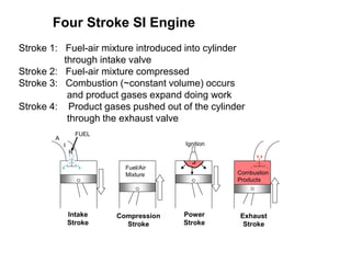
1. Four Stroke SI Engine
Stroke 1: Fuel-air mixture introduced into cylinder
through intake valve
Stroke 2: Fuel-air mixture compressed
Stroke 3: Combustion (~constant volume) occurs
and product gases expand doing work
Stroke 4: Product gases pushed out of the cylinder
through the exhaust valve
Compression
Stroke
Power
Stroke
Exhaust
Stroke
A
I
R
Combustion
Products
Ignition
Intake
Stroke
FUEL
Fuel/Air
Mixture
2. Crank shaft
90o
180o
BC
TC
0o
270o
q
Spark plug for SI engine
Fuel injector for CI engine
Top
Center
(TC)
Bottom
Center
(BC)
Valves
Clearance
volume
Cylinder
wall
Piston
Stroke
Cylinder
Components
3. IVO - intake valve opens, IVC – intake valve closes
EVO – exhaust valve opens, EVC – exhaust valve opens
Xb – burned gas mole fraction
Four-Stroke SI Engine
Exhaust gas
residual
4. Two Stroke SI Engine
Intake (“Scavenging”)
Compression Ignition
Exhaust
Expansion
Fuel-air-oil
mixture
Fuel-air-oil
mixture
compressed
Crank
shaft
Check
valve
Exhaust
port
6. EPO – exhaust port open
EPC – exhaust port closed
IPO – intake port open
IPC – intake port closed
Exhaust area
Intake area
Two-Stroke SI Engine
scavenging
7. Cylinder Arrangement
Single-cylinder engine gives one power stroke per crank revolution
(2 stroke) or two revolutions (4 stroke). The torque pulses are widely
spaced, and engine vibration and smoothness are significant problems.
Used in small engine applications where engine size is more important
Multi-cylinder engines spread out the displacement volume amongst
multiple smaller cylinders. Increased frequency of power strokes
produces smoother torque characteristics. Engine balance (inertia forces
associated with accelerating and decelerating piston) better than single
cylinder.
Most common cylinder arrangements:
- In-line 4-cylinder
- In-line 6-cylinder
- V-6 and V-8
8. Power Regulation (Throttling)
An IC engine is basically an air engine, the more air you get into the
cylinder, the more fuel you can burn, the more power you get out.
The initial pressure in the cylinder is roughly equal to the pressure
in the intake manifold.
Pressure in the intake manifold is varied by opening and closing the
throttle plate to change the pressure drop. Maximum air flow (and
power) achieved at wide-open-throttle (WOT). Minimum air flow
at idle
Patm
Pint < Patm
Intake manifold
Fuel
WOT
Idle
10. Fuel Injection System
Throttle
Fuel tank
Air intake
manifold
During start-up the components are cold so fuel evaporation is very slow, as a result
additional fuel is added through a second injecting valve
11. Superchargers are compressors that are mechanically driven by the
engine crankshaft and thus represent a parasitic load.
Compressor
Patm
Pint > Patm
12. Turbochargers couple a compressor with a turbine driven by the exhaust
gas. The compressor pressure is proportional to the engine speed
13. The peak pressure in the exhaust system is only slightly greater than
atmospheric – small DP across turbine.
In order to produce enough power to run compressor the turbine speed
must be very fast (100k-200k rev/min). It takes time for the turbine to
get up to speed so when the throttle is opened suddenly there is a delay
in achieving peak power - Turbo lag.
Waste gate valve controls the exhaust gas flow rate to the turbine.
It is controlled by the intake manifold pressure
INTAKE
AIR
EXHAUST
FLOW