* Software Engineering2
What is OO?
• Programming languages are of two types: object oriented and procedural
languages. The procedural languages do not have any hidden data, which
makes the code complex.
• Object-orientation programming languages have certain features that make
the code flexible
• Object-orientation is an approach to software development that organizes
both the problem and its solution as a collection of discrete objects
3.
* Software Engineering3
Object-Orientation Characteristics
• Abstraction : The ability to represent data at a very conceptual level
without any details.
• Class : A group of objects that share common properties for data part.
• Encapsulation : It means to enclose all the important information in a
capsule and expose all the other selected information to the outside
world.
• Inheritance : The mechanism by which one class can inherit the
properties of another. It allows a hierarchy of classes to be build, moving
from the most general to the most specific
• Polymorphism : It means the ability to take more than one form. For
example, an operation have different behavior in different instances.
4.
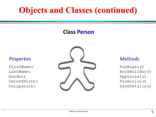
Objects and Classes
•Objects : The instances of a class which are used in real
functionality
• An object’s data are called attributes, and its operations are
called methods
– attributes (such as color, size, location)
– operations or behaviors (such as takeoff, land, repair)
• Each object is an instance of a class
• Class: group of objects that have attributes and behaviors in
common
• Method: a specific implementation of an operation for a certain
class
* Software Engineering 4
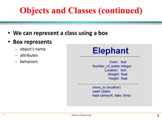
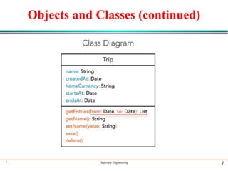
Objects and Classes(continued)
• We can represent a class using a box
• Box represents
– object’s name
– attributes
– behaviors
* Software Engineering 6
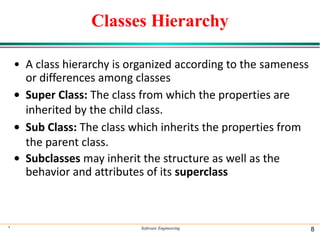
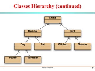
Classes Hierarchy
• Aclass hierarchy is organized according to the sameness
or differences among classes
• Super Class: The class from which the properties are
inherited by the child class.
• Sub Class: The class which inherits the properties from
the parent class.
• Subclasses may inherit the structure as well as the
behavior and attributes of its superclass
* Software Engineering 8
The OO DevelopmentProcess
• One advantage of OO development is its consistency of
language
• Describing classes using OO representation requires
three perspectives
– Static views: descriptions of the object, attributes, behaviors, and
relationships
– Dynamic views: describe communication, control/timing, and the state and
changes in state
– Restrictions: describe constraints on the structure
* Software Engineering 11
Introduction to UML
•A model is a simplified representation of a
complex reality.
• Complex systems and software cannot be
understood without properly modeling them.
• Today, software are getting complex and
consequently we need to understand them
through modeling.
* Software Engineering 13
14.
Unified Modeling Language
•UML is a complete language for capturing knowledge
about a subject and then expressing that knowledge.
i.e. gathering requirements and then modeling those
requirements.
• Such modeling includes two phases :
•Analysis
•Design
* Software Engineering 14
15.
Use-Case Diagram
• UseCase Diagram is used to describe the
functionalities provided by a system and the users
associated with that system.
• The Use case diagram is used to identify the primary
elements and processes that form the system.
• The primary elements are termed as "actors" and the
processes are called "use cases."
• The Use case diagram shows which actors interact
with each use case.
* Software Engineering 15
16.
Elements of ause-case diagram
• Use-case diagrams contain the following
elements:
• Actors, which represent users of a system,
including human users and other systems.
• Use Cases, which represent functionality or
services provided by a system to users.
* Software Engineering 16
17.
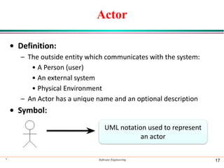
Actor
• Definition:
– Theoutside entity which communicates with the system:
• A Person (user)
• An external system
• Physical Environment
– An Actor has a unique name and an optional description
• Symbol:
* Software Engineering 17
UML notation used to represent
an actor
18.
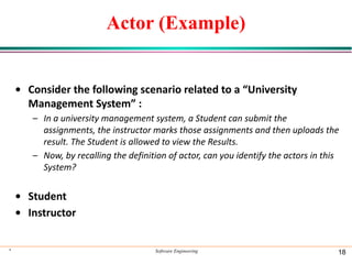
Actor (Example)
• Considerthe following scenario related to a “University
Management System” :
– In a university management system, a Student can submit the
assignments, the instructor marks those assignments and then uploads the
result. The Student is allowed to view the Results.
– Now, by recalling the definition of actor, can you identify the actors in this
System?
• Student
• Instructor
* Software Engineering 18
19.
Use-case
• Represent functionalityor services provided by a
system to users.
• It is a description of set of sequence of actions that a
system perform that produces an observable result.
• A use case represents a class of functionality provided
by the system as an event flow.
• Use cases describe the interaction between a primary
actor and the system itself
* Software Engineering 19
20.
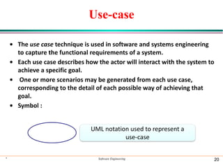
Use-case
• The usecase technique is used in software and systems engineering
to capture the functional requirements of a system.
• Each use case describes how the actor will interact with the system to
achieve a specific goal.
• One or more scenarios may be generated from each use case,
corresponding to the detail of each possible way of achieving that
goal.
• Symbol :
* Software Engineering 20
UML notation used to represent a
use-case
21.
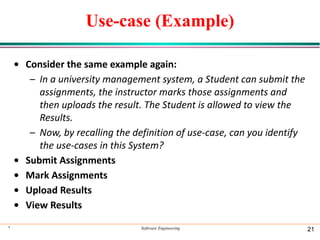
Use-case (Example)
• Considerthe same example again:
– In a university management system, a Student can submit the
assignments, the instructor marks those assignments and
then uploads the result. The Student is allowed to view the
Results.
– Now, by recalling the definition of use-case, can you identify
the use-cases in this System?
• Submit Assignments
• Mark Assignments
• Upload Results
• View Results
* Software Engineering 21
22.
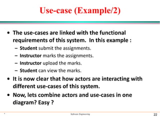
Use-case (Example/2)
• Theuse-cases are linked with the functional
requirements of this system. In this example :
– Student submit the assignments.
– Instructor marks the assignments.
– Instructor upload the marks.
– Student can view the marks.
• It is now clear that how actors are interacting with
different use-cases of this system.
• Now, lets combine actors and use-cases in one
diagram? Easy ?
* Software Engineering 22
23.
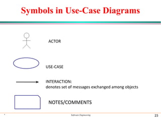
Symbols in Use-CaseDiagrams
* Software Engineering 23
ACTOR
USE-CASE
INTERACTION:
denotes set of messages exchanged among objects
NOTES/COMMENTS
24.
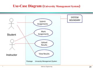
Use-Case Diagram (UniversityManagement System)
* Software Engineering 24
Student
Instructor
Submit
Assignments
Mark
Assignments
Upload
Results
View Results
SYSTEM
BOUNDARY
Package: University Management System
25.
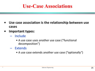
Use-Case Associations
• Usecase association is the relationship between use
cases
• Important types:
– Include
• A use case uses another use case (“functional
decomposition”)
– Extends
• A use case extends another use case (“optionally“)
* Software Engineering 25
26.
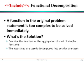
<<Include>>: Functional Decomposition
•A function in the original problem
statement is too complex to be solved
immediately.
• What’s the Solution?
⚫ Describe the function as the aggregation of a set of simpler
functions
⚫ The associated use case is decomposed into smaller use cases
* Software Engineering 26
27.
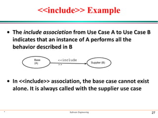
<<include>> Example
• Theinclude association from Use Case A to Use Case B
indicates that an instance of A performs all the
behavior described in B
• In <<include>> association, the base case cannot exist
alone. It is always called with the supplier use case
* Software Engineering 27
<<include
>>
Base
(A) Supplier (B)
28.
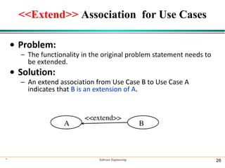
<<Extend>> Association forUse Cases
• Problem:
– The functionality in the original problem statement needs to
be extended.
• Solution:
– An extend association from Use Case B to Use Case A
indicates that B is an extension of A.
* Software Engineering 28
A B
<<extend>>
29.
Example
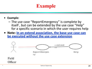
• Example:
– Theuse case “ReportEmergency” is complete by
itself , but can be extended by the use case “Help”
for a specific scenario in which the user requires help
• Note: In an extend association, the base use case can
be executed without the use case extension
* Software Engineering 29
ReportEmergen
cy
Field
Officer
<<extend
>>
Help
30.
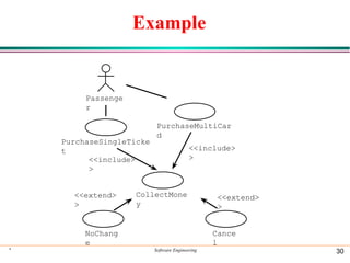
Example
* Software Engineering30
Passenge
r
PurchaseSingleTicke
t
PurchaseMultiCar
d
NoChang
e
<<extend>
>
Cance
l
<<extend>
>
<<include>
>
CollectMone
y
<<include>
>