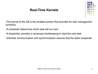
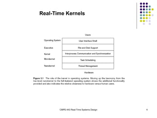
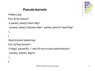
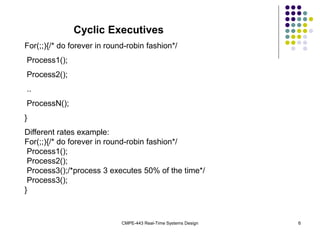
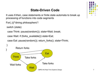
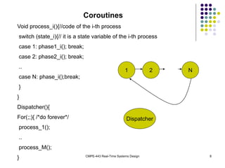
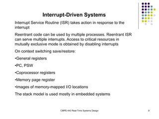
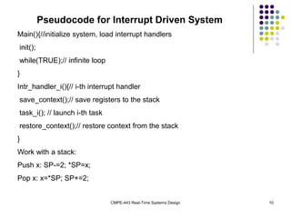
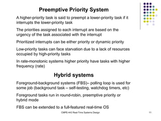
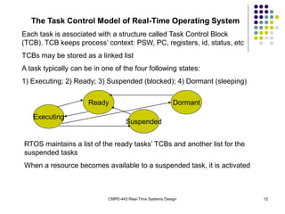
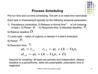
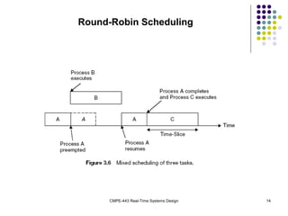
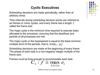
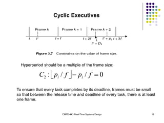
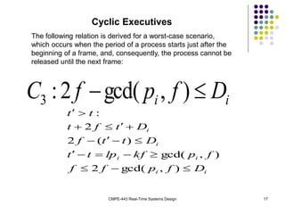
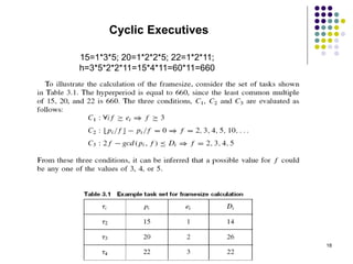
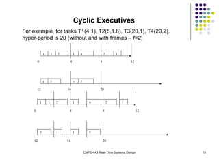
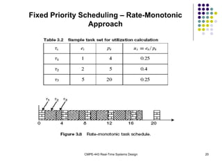
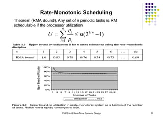
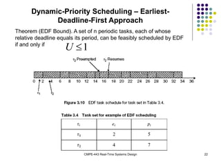
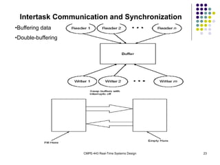
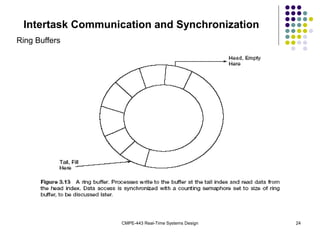
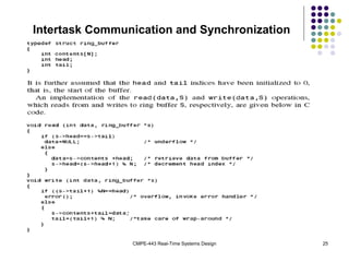
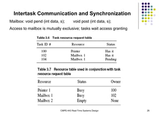
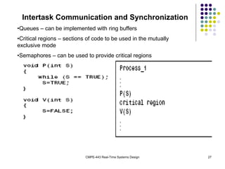
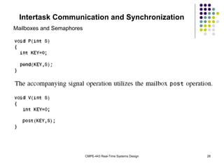
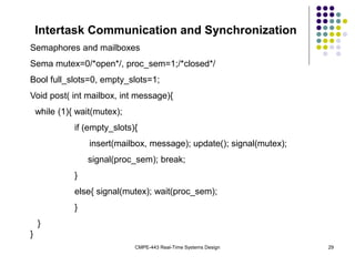
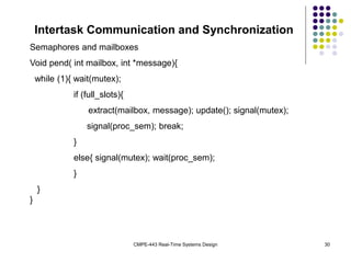
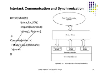
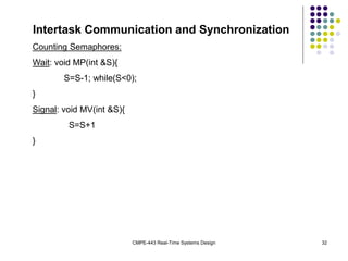
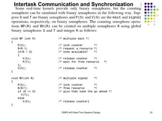
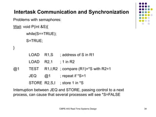
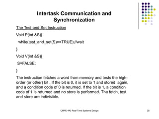
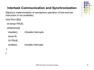
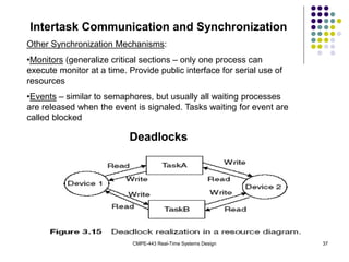
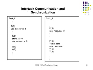
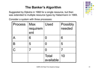
CMPE-443 Real-Time Systems Design 1
Real-Time Operating Systems
 Real-Time Kernels
 Theoretical Foundations of RTOS
 Intertask Communication & Synchronization
 Memory Management
 Case Study
CMPE-443 Real-Time Systems Design 2
Real-Time Kernels
 A process is an abstraction of a running
program and is the logical unit of work
scheduled by OS
 Threads are light-weighted processes sharing
resources of the parent process
 RTOS task management functions:
scheduling, dispatching, intercommunication
and synchronization
CMPE-443 Real-Time Systems Design 3
Real-Time Kernels
•The kernel of the OS is the smallest portion that provides for task management
functions
•A scheduler determines which task will run next
•A dispatcher provides a necessary bookkeeping to start the next task
•Intertask communication and synchronization assures that the tasks cooperate
CMPE-443 Real-Time Systems Design 4
Real-Time Kernels
CMPE-443 Real-Time Systems Design 5
Pseudo-kernels
•Polled Loop
For(;;){/*do forever*/
if (packet_here){/*check flag*/
process_data();/*process data*/ packet_here=0;/*reset flag*/
}
}
•Synchronized polled loop
For(;;){/*loop forever*/
if (flag){ pause(20); /* wait 20 ms to avoid switch-bounce*/
process_event(); flag=0;
}
}
CMPE-443 Real-Time Systems Design 6
Cyclic Executives
For(;;){/* do forever in round-robin fashion*/
Process1();
Process2();
..
ProcessN();
}
Different rates example:
For(;;){/* do forever in round-robin fashion*/
Process1();
Process2();
Process3();/*process 3 executes 50% of the time*/
Process3();
}
CMPE-443 Real-Time Systems Design 7
State-Driven Code
It uses if-then, case statements or finite state automata to break up
processing of functions into code segments
For(;;){/*dining philosophers*/
switch (state)
case Think: pause(random()); state=Wait; break;
case Wait: if (forks_available()) state=Eat;
case Eat: pause(random()); return_forks(); state=Think;
}
}
Think
Eat
Wait
Return forks
Take forks
Wait forks
Take forks
CMPE-443 Real-Time Systems Design 8
Coroutines
Void process_i(){//code of the i-th process
switch (state_i){// it is a state variable of the i-th process
case 1: phase1_i(); break;
case 2: phase2_i(); break;
..
case N: phase_i();break;
}
}
Dispatcher(){
For(;;){ /*do forever*/
process_1();
..
process_M();
}
1 2 N
Dispatcher
CMPE-443 Real-Time Systems Design 9
Interrupt-Driven Systems
Interrupt Service Routine (ISR) takes action in response to the
interrupt
Reentrant code can be used by multiple processes. Reentrant ISR
can serve multiple interrupts. Access to critical resources in
mutually exclusive mode is obtained by disabling interrupts
On context switching save/restore:
•General registers
•PC, PSW
•Coprocessor registers
•Memory page register
•Images of memory-mapped I/O locations
The stack model is used mostly in embedded systems
CMPE-443 Real-Time Systems Design 10
Pseudocode for Interrupt Driven System
Main(){//initialize system, load interrupt handlers
init();
while(TRUE);// infinite loop
}
Intr_handler_i(){// i-th interrupt handler
save_context();// save registers to the stack
task_i(); // launch i-th task
restore_context();// restore context from the stack
}
Work with a stack:
Push x: SP-=2; *SP=x;
Pop x: x=*SP; SP+=2;
CMPE-443 Real-Time Systems Design 11
Preemptive Priority System
A higher-priority task is said to preempt a lower-priority task if it
interrupts the lower-priority task
The priorities assigned to each interrupt are based on the
urgency of the task associated with the interrupt
Prioritized interrupts can be either priority or dynamic priority
Low-priority tasks can face starvation due to a lack of resources
occupied by high-priority tasks
In rate-monotonic systems higher priority have tasks with higher
frequency (rate)
Hybrid systems
Foreground-background systems (FBS)– polling loop is used for
some job (background task – self-testing, watchdog timers, etc)
Foreground tasks run in round-robin, preemptive priority or
hybrid mode
FBS can be extended to a full-featured real-time OS
CMPE-443 Real-Time Systems Design 12
The Task Control Model of Real-Time Operating System
Each task is associated with a structure called Task Control Block
(TCB). TCB keeps process’ context: PSW, PC, registers, id, status, etc
TCBs may be stored as a linked list
A task typically can be in one of the four following states:
1) Executing; 2) Ready; 3) Suspended (blocked); 4) Dormant (sleeping)
Executing
Ready
Suspended
Dormant
RTOS maintains a list of the ready tasks’ TCBs and another list for the
suspended tasks
When a resource becomes available to a suspended task, it is activated
CMPE-443 Real-Time Systems Design 13
Process Scheduling
Pre-run time and run-time scheduling. The aim is to meet time restrictions
Each task is characterized typically by the following temporal parameters:
1) Precedence constraints; 2) Release or Arrival time of j-th instance
of task i; 3) Phase ; 4) Response time; 5) Absolute deadline
6) Relative deadline
7) Laxity type – notion of urgency or leeway in a task’s execution
8) Period
9) Execution time
j
i
r,
i
 i
d
i
D
i
p
i
e
i
i
i
k
i
i
i
k
i
i
i
D
p
k
d
p
k
r
r








)
1
(
)
1
(
,
,
1
,



Assume for simplicity: all tasks are periodic and independent, relative
deadline is a period/frame, tasks are preemptible, preemption time is
neglected
CMPE-443 Real-Time Systems Design 14
Round-Robin Scheduling
CMPE-443 Real-Time Systems Design 15
Cyclic Executives
Scheduling decisions are made periodically, rather than at
arbitrary times
Time intervals during scheduling decision points are referred to
as frames or minor cycles, and every frame has a length, f,
called the frame size
The major cycle is the minimum time required to execute tasks
allocated to the processor, ensuring that the deadlines and
periods of all processes are met
The major cycle or the hyperperiod is equal to the least common
multiple (lcm) of the periods, that is, lcm(p1,..,pn)
Scheduling decisions are made at the beginning of every frame.
The phase of each task is a non-negative integer multiple of the
frame size.
Frames must be long enough to accommodate each task:
i
n
i
e
f
C



1
1 max
:
CMPE-443 Real-Time Systems Design 16
Cyclic Executives
Hyperperiod should be a multiple of the frame size:
  0
/
/
:
2 
 f
p
f
p
C i
i
To ensure that every task completes by its deadline, frames must be small
so that between the release time and deadline of every task, there is at least
one frame.
CMPE-443 Real-Time Systems Design 17
Cyclic Executives
The following relation is derived for a worst-case scenario,
which occurs when the period of a process starts just after the
beginning of a frame, and, consequently, the process cannot be
released until the next frame:
i
i D
f
p
f
C 
 )
,
gcd(
2
:
3
i
i
i
i
i
i
D
f
p
f
f
f
p
kf
lp
t
t
D
t
t
f
D
t
f
t
t
t


















)
,
gcd(
2
)
,
gcd(
)
(
2
2
:
CMPE-443 Real-Time Systems Design 18
Cyclic Executives
15=1*3*5; 20=1*2*2*5; 22=1*2*11;
h=3*5*2*2*11=15*4*11=60*11=660
CMPE-443 Real-Time Systems Design 19
Cyclic Executives
For example, for tasks T1(4,1), T2(5,1.8), T3(20,1), T4(20,2),
hyper-period is 20 (without and with frames – f=2)
0 4
1 1 2
2
1 3 1 4 1
2
8 12
12 16 20
2
0 4
4
2
1 3 2
1 1
2
8 12
12 16 20
1 2
1
CMPE-443 Real-Time Systems Design 20
Fixed Priority Scheduling – Rate-Monotonic
Approach
CMPE-443 Real-Time Systems Design 21
Rate-Monotonic Scheduling
Theorem (RMA Bound). Any set of n periodic tasks is RM
schedulable if the processor utilization





n
i
n
i
i
n
p
e
U
1
/
1
)
1
2
(
CMPE-443 Real-Time Systems Design 22
Dynamic-Priority Scheduling – Earliest-
Deadline-First Approach
Theorem (EDF Bound). A set of n periodic tasks, each of whose
relative deadline equals its period, can be feasibly scheduled by EDF
if and only if
1

U
CMPE-443 Real-Time Systems Design 23
Intertask Communication and Synchronization
•Buffering data
•Double-buffering
CMPE-443 Real-Time Systems Design 24
Intertask Communication and Synchronization
Ring Buffers
CMPE-443 Real-Time Systems Design 25
Intertask Communication and Synchronization
CMPE-443 Real-Time Systems Design 26
Intertask Communication and Synchronization
Mailbox: void pend (int data, s); void post (int data, s);
Access to mailbox is mutually exclusive; tasks wait access granting
CMPE-443 Real-Time Systems Design 27
Intertask Communication and Synchronization
•Queues – can be implemented with ring buffers
•Critical regions – sections of code to be used in the mutually
exclusive mode
•Semaphores – can be used to provide critical regions
CMPE-443 Real-Time Systems Design 28
Intertask Communication and Synchronization
Mailboxes and Semaphores
CMPE-443 Real-Time Systems Design 29
Intertask Communication and Synchronization
Semaphores and mailboxes
Sema mutex=0/*open*/, proc_sem=1;/*closed*/
Bool full_slots=0, empty_slots=1;
Void post( int mailbox, int message){
while (1){ wait(mutex);
if (empty_slots){
insert(mailbox, message); update(); signal(mutex);
signal(proc_sem); break;
}
else{ signal(mutex); wait(proc_sem);
}
}
}
CMPE-443 Real-Time Systems Design 30
Intertask Communication and Synchronization
Semaphores and mailboxes
Void pend( int mailbox, int *message){
while (1){ wait(mutex);
if (full_slots){
extract(mailbox, message); update(); signal(mutex);
signal(proc_sem); break;
}
else{ signal(mutex); wait(proc_sem);
}
}
}
CMPE-443 Real-Time Systems Design 31
Intertask Communication and Synchronization
Driver{ while(1){
if(data_for_I/O){
prepare(command);
V(busy); P(done);}
}}
Controller{while(1){
P(busy); exec(command);
V(done);
}}
CMPE-443 Real-Time Systems Design 32
Intertask Communication and Synchronization
Counting Semaphores:
Wait: void MP(int &S){
S=S-1; while(S<0);
}
Signal: void MV(int &S){
S=S+1
}
CMPE-443 Real-Time Systems Design 33
Intertask Communication and Synchronization
CMPE-443 Real-Time Systems Design 34
Intertask Communication and Synchronization
Problems with semaphores:
Wait: void P(int &S){
while(S==TRUE);
S=TRUE;
}
LOAD R1,S ; address of S in R1
LOAD R2,1 ; 1 in R2
@1 TEST R1,I,R2 ; compare (R1)=*S with R2=1
JEQ @1 ; repeat if *S=1
STORE R2,S,I ; store 1 in *S
Interruption between JEQ and STORE, passing control to a next
process, can cause that several processes will see *S=FALSE
CMPE-443 Real-Time Systems Design 35
Intertask Communication and
Synchronization
The Test-and-Set Instruction
Void P(int &S){
while(test_and_set(S)==TRUE);//wait
}
Void V(int &S){
S=FALSE;
}
The instruction fetches a word from memory and tests the high-
order (or other) bit . If the bit is 0, it is set to 1 and stored again,
and a condition code of 0 is returned. If the bit is 1, a condition
code of 1 is returned and no store is performed. The fetch, test
and store are indivisible.
CMPE-443 Real-Time Systems Design 36
Intertask Communication and Synchronization
Dijkstra’s implementation of semaphore operation (if test-and-set
instruction is not available):
Void P(int &S){
int temp=TRUE;
while(temp){
disable(); //disable interrupts
temp=S;
S=TRUE;
enable(); //enable interrupts
}
}
CMPE-443 Real-Time Systems Design 37
Intertask Communication and Synchronization
Other Synchronization Mechanisms:
•Monitors (generalize critical sections – only one process can
execute monitor at a time. Provide public interface for serial use of
resources
•Events – similar to semaphores, but usually all waiting processes
are released when the event is signaled. Tasks waiting for event are
called blocked
Deadlocks
CMPE-443 Real-Time Systems Design 38
Intertask Communication and
Synchronization
Deadllocks:
CMPE-443 Real-Time Systems Design 39
Deadlocks
Four conditions are necessary for deadlock:
•Mutual exclusion
•Circular wait
•Hold and wait
•No preemption
Eliminating any one of the four necessary conditions will prevent
deadlock from occurring
One way to eliminate circular wait is to number resources and give
all the resources with the numbers greater or equal than minimal
required to processes. For example: Disk – 1, Printer – 2, Motor
control – 3, Monitor – 4. If a process wishes to use printer, it will be
assigned printer, motor control and monitor. If another process
requires monitor, it will have wait until the monitor will be released.
This may lead to starvation.
CMPE-443 Real-Time Systems Design 40
Deadlock avoidance
To avoid deadlocks, it is recommended :
•Minimize the number of critical regions as well as minimizing
their size
•All processes must release any lock before returning to the
calling function
•Do not suspend any task while it controls a critical region
•All critical regions must be error-free
•Do not lock devices in interrupt handlers
•Always perform validity checks on pointers used within critical
regions.
It is difficult to follow these recommendations
CMPE-443 Real-Time Systems Design 41
The Banker’s Algorithm
Suggested by Dijkstra in 1968 for a single resource, but then
was extended to multiple resource types by Habermann in 1969.
Consider a system with three processes:
Process Max
requirem
ent
Used Possibly
needed
A 6 0 6
B 5 0 5
C 7 0 7
Total
available
10
CMPE-443 Real-Time Systems Design 42
The Banker’s Algorithm
When resources are requested, the operating system updates the
table, ensuring that a possible deadlock state is not reached. An
example of a “safe state” is
Process Max
requirem
ent
Used Possibly
needed
A 6 2 4
B 5 3 2
C 7 1 6
Total
available
4
CMPE-443 Real-Time Systems Design 43
The Banker’s Algorithm
An example of an “unsafe state” is:
Process Max
requirem
ent
Used Possibly
needed
A 6 4 2
B 5 3 2
C 7 2 5
Total
available
1
CMPE-443 Real-Time Systems Design 44
The Banker’s Algorithm
The case of multiple resources. Initial resource state:
Safe state:
CMPE-443 Real-Time Systems Design 45
The Banker’s Algorithm

RTOS Material hfffffffffffffffffffffffffffffffffffff

  • 1.
    CMPE-443 Real-Time SystemsDesign 1 Real-Time Operating Systems  Real-Time Kernels  Theoretical Foundations of RTOS  Intertask Communication & Synchronization  Memory Management  Case Study
  • 2.
    CMPE-443 Real-Time SystemsDesign 2 Real-Time Kernels  A process is an abstraction of a running program and is the logical unit of work scheduled by OS  Threads are light-weighted processes sharing resources of the parent process  RTOS task management functions: scheduling, dispatching, intercommunication and synchronization
  • 3.
    CMPE-443 Real-Time SystemsDesign 3 Real-Time Kernels •The kernel of the OS is the smallest portion that provides for task management functions •A scheduler determines which task will run next •A dispatcher provides a necessary bookkeeping to start the next task •Intertask communication and synchronization assures that the tasks cooperate
  • 4.
    CMPE-443 Real-Time SystemsDesign 4 Real-Time Kernels
  • 5.
    CMPE-443 Real-Time SystemsDesign 5 Pseudo-kernels •Polled Loop For(;;){/*do forever*/ if (packet_here){/*check flag*/ process_data();/*process data*/ packet_here=0;/*reset flag*/ } } •Synchronized polled loop For(;;){/*loop forever*/ if (flag){ pause(20); /* wait 20 ms to avoid switch-bounce*/ process_event(); flag=0; } }
  • 6.
    CMPE-443 Real-Time SystemsDesign 6 Cyclic Executives For(;;){/* do forever in round-robin fashion*/ Process1(); Process2(); .. ProcessN(); } Different rates example: For(;;){/* do forever in round-robin fashion*/ Process1(); Process2(); Process3();/*process 3 executes 50% of the time*/ Process3(); }
  • 7.
    CMPE-443 Real-Time SystemsDesign 7 State-Driven Code It uses if-then, case statements or finite state automata to break up processing of functions into code segments For(;;){/*dining philosophers*/ switch (state) case Think: pause(random()); state=Wait; break; case Wait: if (forks_available()) state=Eat; case Eat: pause(random()); return_forks(); state=Think; } } Think Eat Wait Return forks Take forks Wait forks Take forks
  • 8.
    CMPE-443 Real-Time SystemsDesign 8 Coroutines Void process_i(){//code of the i-th process switch (state_i){// it is a state variable of the i-th process case 1: phase1_i(); break; case 2: phase2_i(); break; .. case N: phase_i();break; } } Dispatcher(){ For(;;){ /*do forever*/ process_1(); .. process_M(); } 1 2 N Dispatcher
  • 9.
    CMPE-443 Real-Time SystemsDesign 9 Interrupt-Driven Systems Interrupt Service Routine (ISR) takes action in response to the interrupt Reentrant code can be used by multiple processes. Reentrant ISR can serve multiple interrupts. Access to critical resources in mutually exclusive mode is obtained by disabling interrupts On context switching save/restore: •General registers •PC, PSW •Coprocessor registers •Memory page register •Images of memory-mapped I/O locations The stack model is used mostly in embedded systems
  • 10.
    CMPE-443 Real-Time SystemsDesign 10 Pseudocode for Interrupt Driven System Main(){//initialize system, load interrupt handlers init(); while(TRUE);// infinite loop } Intr_handler_i(){// i-th interrupt handler save_context();// save registers to the stack task_i(); // launch i-th task restore_context();// restore context from the stack } Work with a stack: Push x: SP-=2; *SP=x; Pop x: x=*SP; SP+=2;
  • 11.
    CMPE-443 Real-Time SystemsDesign 11 Preemptive Priority System A higher-priority task is said to preempt a lower-priority task if it interrupts the lower-priority task The priorities assigned to each interrupt are based on the urgency of the task associated with the interrupt Prioritized interrupts can be either priority or dynamic priority Low-priority tasks can face starvation due to a lack of resources occupied by high-priority tasks In rate-monotonic systems higher priority have tasks with higher frequency (rate) Hybrid systems Foreground-background systems (FBS)– polling loop is used for some job (background task – self-testing, watchdog timers, etc) Foreground tasks run in round-robin, preemptive priority or hybrid mode FBS can be extended to a full-featured real-time OS
  • 12.
    CMPE-443 Real-Time SystemsDesign 12 The Task Control Model of Real-Time Operating System Each task is associated with a structure called Task Control Block (TCB). TCB keeps process’ context: PSW, PC, registers, id, status, etc TCBs may be stored as a linked list A task typically can be in one of the four following states: 1) Executing; 2) Ready; 3) Suspended (blocked); 4) Dormant (sleeping) Executing Ready Suspended Dormant RTOS maintains a list of the ready tasks’ TCBs and another list for the suspended tasks When a resource becomes available to a suspended task, it is activated
  • 13.
    CMPE-443 Real-Time SystemsDesign 13 Process Scheduling Pre-run time and run-time scheduling. The aim is to meet time restrictions Each task is characterized typically by the following temporal parameters: 1) Precedence constraints; 2) Release or Arrival time of j-th instance of task i; 3) Phase ; 4) Response time; 5) Absolute deadline 6) Relative deadline 7) Laxity type – notion of urgency or leeway in a task’s execution 8) Period 9) Execution time j i r, i  i d i D i p i e i i i k i i i k i i i D p k d p k r r         ) 1 ( ) 1 ( , , 1 ,    Assume for simplicity: all tasks are periodic and independent, relative deadline is a period/frame, tasks are preemptible, preemption time is neglected
  • 14.
    CMPE-443 Real-Time SystemsDesign 14 Round-Robin Scheduling
  • 15.
    CMPE-443 Real-Time SystemsDesign 15 Cyclic Executives Scheduling decisions are made periodically, rather than at arbitrary times Time intervals during scheduling decision points are referred to as frames or minor cycles, and every frame has a length, f, called the frame size The major cycle is the minimum time required to execute tasks allocated to the processor, ensuring that the deadlines and periods of all processes are met The major cycle or the hyperperiod is equal to the least common multiple (lcm) of the periods, that is, lcm(p1,..,pn) Scheduling decisions are made at the beginning of every frame. The phase of each task is a non-negative integer multiple of the frame size. Frames must be long enough to accommodate each task: i n i e f C    1 1 max :
  • 16.
    CMPE-443 Real-Time SystemsDesign 16 Cyclic Executives Hyperperiod should be a multiple of the frame size:   0 / / : 2   f p f p C i i To ensure that every task completes by its deadline, frames must be small so that between the release time and deadline of every task, there is at least one frame.
  • 17.
    CMPE-443 Real-Time SystemsDesign 17 Cyclic Executives The following relation is derived for a worst-case scenario, which occurs when the period of a process starts just after the beginning of a frame, and, consequently, the process cannot be released until the next frame: i i D f p f C   ) , gcd( 2 : 3 i i i i i i D f p f f f p kf lp t t D t t f D t f t t t                   ) , gcd( 2 ) , gcd( ) ( 2 2 :
  • 18.
    CMPE-443 Real-Time SystemsDesign 18 Cyclic Executives 15=1*3*5; 20=1*2*2*5; 22=1*2*11; h=3*5*2*2*11=15*4*11=60*11=660
  • 19.
    CMPE-443 Real-Time SystemsDesign 19 Cyclic Executives For example, for tasks T1(4,1), T2(5,1.8), T3(20,1), T4(20,2), hyper-period is 20 (without and with frames – f=2) 0 4 1 1 2 2 1 3 1 4 1 2 8 12 12 16 20 2 0 4 4 2 1 3 2 1 1 2 8 12 12 16 20 1 2 1
  • 20.
    CMPE-443 Real-Time SystemsDesign 20 Fixed Priority Scheduling – Rate-Monotonic Approach
  • 21.
    CMPE-443 Real-Time SystemsDesign 21 Rate-Monotonic Scheduling Theorem (RMA Bound). Any set of n periodic tasks is RM schedulable if the processor utilization      n i n i i n p e U 1 / 1 ) 1 2 (
  • 22.
    CMPE-443 Real-Time SystemsDesign 22 Dynamic-Priority Scheduling – Earliest- Deadline-First Approach Theorem (EDF Bound). A set of n periodic tasks, each of whose relative deadline equals its period, can be feasibly scheduled by EDF if and only if 1  U
  • 23.
    CMPE-443 Real-Time SystemsDesign 23 Intertask Communication and Synchronization •Buffering data •Double-buffering
  • 24.
    CMPE-443 Real-Time SystemsDesign 24 Intertask Communication and Synchronization Ring Buffers
  • 25.
    CMPE-443 Real-Time SystemsDesign 25 Intertask Communication and Synchronization
  • 26.
    CMPE-443 Real-Time SystemsDesign 26 Intertask Communication and Synchronization Mailbox: void pend (int data, s); void post (int data, s); Access to mailbox is mutually exclusive; tasks wait access granting
  • 27.
    CMPE-443 Real-Time SystemsDesign 27 Intertask Communication and Synchronization •Queues – can be implemented with ring buffers •Critical regions – sections of code to be used in the mutually exclusive mode •Semaphores – can be used to provide critical regions
  • 28.
    CMPE-443 Real-Time SystemsDesign 28 Intertask Communication and Synchronization Mailboxes and Semaphores
  • 29.
    CMPE-443 Real-Time SystemsDesign 29 Intertask Communication and Synchronization Semaphores and mailboxes Sema mutex=0/*open*/, proc_sem=1;/*closed*/ Bool full_slots=0, empty_slots=1; Void post( int mailbox, int message){ while (1){ wait(mutex); if (empty_slots){ insert(mailbox, message); update(); signal(mutex); signal(proc_sem); break; } else{ signal(mutex); wait(proc_sem); } } }
  • 30.
    CMPE-443 Real-Time SystemsDesign 30 Intertask Communication and Synchronization Semaphores and mailboxes Void pend( int mailbox, int *message){ while (1){ wait(mutex); if (full_slots){ extract(mailbox, message); update(); signal(mutex); signal(proc_sem); break; } else{ signal(mutex); wait(proc_sem); } } }
  • 31.
    CMPE-443 Real-Time SystemsDesign 31 Intertask Communication and Synchronization Driver{ while(1){ if(data_for_I/O){ prepare(command); V(busy); P(done);} }} Controller{while(1){ P(busy); exec(command); V(done); }}
  • 32.
    CMPE-443 Real-Time SystemsDesign 32 Intertask Communication and Synchronization Counting Semaphores: Wait: void MP(int &S){ S=S-1; while(S<0); } Signal: void MV(int &S){ S=S+1 }
  • 33.
    CMPE-443 Real-Time SystemsDesign 33 Intertask Communication and Synchronization
  • 34.
    CMPE-443 Real-Time SystemsDesign 34 Intertask Communication and Synchronization Problems with semaphores: Wait: void P(int &S){ while(S==TRUE); S=TRUE; } LOAD R1,S ; address of S in R1 LOAD R2,1 ; 1 in R2 @1 TEST R1,I,R2 ; compare (R1)=*S with R2=1 JEQ @1 ; repeat if *S=1 STORE R2,S,I ; store 1 in *S Interruption between JEQ and STORE, passing control to a next process, can cause that several processes will see *S=FALSE
  • 35.
    CMPE-443 Real-Time SystemsDesign 35 Intertask Communication and Synchronization The Test-and-Set Instruction Void P(int &S){ while(test_and_set(S)==TRUE);//wait } Void V(int &S){ S=FALSE; } The instruction fetches a word from memory and tests the high- order (or other) bit . If the bit is 0, it is set to 1 and stored again, and a condition code of 0 is returned. If the bit is 1, a condition code of 1 is returned and no store is performed. The fetch, test and store are indivisible.
  • 36.
    CMPE-443 Real-Time SystemsDesign 36 Intertask Communication and Synchronization Dijkstra’s implementation of semaphore operation (if test-and-set instruction is not available): Void P(int &S){ int temp=TRUE; while(temp){ disable(); //disable interrupts temp=S; S=TRUE; enable(); //enable interrupts } }
  • 37.
    CMPE-443 Real-Time SystemsDesign 37 Intertask Communication and Synchronization Other Synchronization Mechanisms: •Monitors (generalize critical sections – only one process can execute monitor at a time. Provide public interface for serial use of resources •Events – similar to semaphores, but usually all waiting processes are released when the event is signaled. Tasks waiting for event are called blocked Deadlocks
  • 38.
    CMPE-443 Real-Time SystemsDesign 38 Intertask Communication and Synchronization Deadllocks:
  • 39.
    CMPE-443 Real-Time SystemsDesign 39 Deadlocks Four conditions are necessary for deadlock: •Mutual exclusion •Circular wait •Hold and wait •No preemption Eliminating any one of the four necessary conditions will prevent deadlock from occurring One way to eliminate circular wait is to number resources and give all the resources with the numbers greater or equal than minimal required to processes. For example: Disk – 1, Printer – 2, Motor control – 3, Monitor – 4. If a process wishes to use printer, it will be assigned printer, motor control and monitor. If another process requires monitor, it will have wait until the monitor will be released. This may lead to starvation.
  • 40.
    CMPE-443 Real-Time SystemsDesign 40 Deadlock avoidance To avoid deadlocks, it is recommended : •Minimize the number of critical regions as well as minimizing their size •All processes must release any lock before returning to the calling function •Do not suspend any task while it controls a critical region •All critical regions must be error-free •Do not lock devices in interrupt handlers •Always perform validity checks on pointers used within critical regions. It is difficult to follow these recommendations
  • 41.
    CMPE-443 Real-Time SystemsDesign 41 The Banker’s Algorithm Suggested by Dijkstra in 1968 for a single resource, but then was extended to multiple resource types by Habermann in 1969. Consider a system with three processes: Process Max requirem ent Used Possibly needed A 6 0 6 B 5 0 5 C 7 0 7 Total available 10
  • 42.
    CMPE-443 Real-Time SystemsDesign 42 The Banker’s Algorithm When resources are requested, the operating system updates the table, ensuring that a possible deadlock state is not reached. An example of a “safe state” is Process Max requirem ent Used Possibly needed A 6 2 4 B 5 3 2 C 7 1 6 Total available 4
  • 43.
    CMPE-443 Real-Time SystemsDesign 43 The Banker’s Algorithm An example of an “unsafe state” is: Process Max requirem ent Used Possibly needed A 6 4 2 B 5 3 2 C 7 2 5 Total available 1
  • 44.
    CMPE-443 Real-Time SystemsDesign 44 The Banker’s Algorithm The case of multiple resources. Initial resource state: Safe state:
  • 45.
    CMPE-443 Real-Time SystemsDesign 45 The Banker’s Algorithm