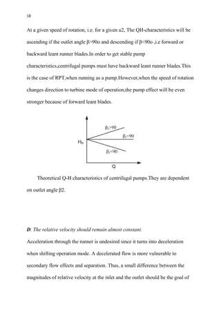
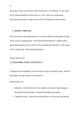
SlideShare a Scribd company logo
1 of 42
Download to read offline
1
DESIGN AND ANALYSIS OF REVERSIBLE PUMP TURBINE
An undergraduate thesis submitted in partial fulfillment of the requirements
for the award of the degree of
Bachelor of Technology in Mechanical Engineering
By
Arun Kumar Yadav (12/ME/24)
Mustafizur Rahaman (12/ME/25)
Souvik Das (12/ME/45)
Arvind Kumar Gupta (12/ME/47)
Abhishek Paul (12/ME/48)
Aman Verma (12/ME/101)
Nihal Kumar (12/ME/103)
Under the supervision of:
Dr. SUBHAS CHANDRA RANA
Assistant Professor
DEPARTMENT OF MECHANICAL ENGINEERING
NATIONAL INSTITUTE OF TECHNOLOGY DURGAPUR
DURGAPUR-713209
WEST BENGAL, INDIA
2016
2
CERTIFICATE OF APPROVAL
The following thesis is hereby approved as a creditable
study of an Engineering subject, carried out and presented
in a manner satisfactory to warrant its acceptance as a
prerequisite to the degree for which it has been submitted.
It is to be understood that this approval of the undersigned
do not necessarily endorse or approve any statement made,
opinion expressed or conclusion drawn therein, but approve
the thesis only for the purpose for which it has been
submitted.
SIGNATURE OF SUPERVISOR THESIS EXAMINER
3
ACKNOWLEDGEMENT:
We take this opportunity to express our profound gratitude and deep regards
to my supervisor Dr Subhas Chandra Rana for his exemplary guidance,
monitoring and constant encouragement throughout the duration of this
project. His valuable suggestions were of immense help throughout our
research work. The blessings, help and guidance given by him time to time shall
carry us a long way in the journey of life on which we are about to embark.
4
CONTENTS
TOPICS PAGE NUMBER
1. Abstract ………………………………………………………………………………………………………………………..5
2. Brief Introduction…………………………………………………………………………………………………….…….5
3. Hydraulic Design Issues………………………………………………………………………………………………….7
3.1. Euler’s Equation………………………………………………………………………………………………………8
3.2. Stability of pumps……………………………………………………………………………..…….…………….14
4. Design process…………………………………………………………………………………………………………….19
4.1. Maximum Efficiency………………………………………………………………………………….….……….21
4.2. Cavitation……………………………………………..……………………………………………………...…..….23
4.3. Net positive suction head(NPSH)……………………….………………………………………..….….…25
4.4. Free Vortex Theory………………………………………………………………………………………………..28
5. Design parameters and output……………………………………………………………………………………..29
6. Modelling……………………………………………………………………………………………………………………..34
6.1. Assembly of RPT Housing……………………………………………………………………………………….35
7. CFD ……………………………………………………………………………………………………………………………...37
7.1. CFD Analysis…………………………………………………………………………………………………………..39
7.2. Results of CFD Analysis…………………………………………………………………………………………..41
8. Conclusion…………………………………………………………………………………………………………………….41
9. References……………………………………………………………………………………………………………………42
10. Websites……………………………………………………………………………………………………………………….42
5
1. ABSTRACT:
A reversible pump turbine is a machine that can operate in three modes of
operation i.e. in pumping mode, in turbine mode and in phase compensating
mode (idle speed). Most hydropower plants in are run-off type, which cannot
supply the designed amount of energy during dry season and peak demand
period resulting in energy crisis. Therefore, pumped storage plants can be an
ideal solution to meet the current energy needs of the country. Most of these
storage plants make use of a single unit acting both as turbine as well as pump;
hence aptly called Reversible Pump Turbine (RPT). This paper explains the new
application concept for use of such RPTs as auxiliary unit to supplement the
main power unit in hydropower plants.
The design is performed in two steps. The first step is an analytical design,
which gives an initial geometry of the RPT runner. The process resulted in a
runner of larger size than a normal Francis runner for same parameters since it
has to work as pump as well. The next step involves CFD analysis under which
the simulation of the RPT in turbine mode is done.
2. BRIEF INTRODUCTION:
A Pumped-storage plant stores energy by pumping water from a lower
reservoir at off peak hours of electric demand by means of surplus power into a
high level reservoir, in order to utilize the stored energy at periods when it is
6
most needed.It is probably the best way to compensate for the gap between
produced and consumed power. These pumped storage system use a single
pump/turbine unit i.e. Reversible Pump Turbine to efficiently and economically
store electrical energy during periods of low demand to meet peak load
demands.As far as our scope of work is concerned we have immaculately tried
to design the differents parts of the RPT using SOLIDWORKS,CATIA for the
modelling part and ANSYS for consequent simulation and analysis.
Schematic diagram of pumped storage plant
7
2. HYDRAULIC DESIGN ISSUES:
An RPT acts as a water passageway with a shiftable body component
selectively displaceable to achieve alternatively, either an energy generation or
an energy accumulation mode The design of a pump turbine is similar to the
design of a high head Francis turbine. However, the factors that need to be
considered while designing an RPT are as follows:
A. Pump head should be higher than in turbine mode due to loss in the
waterways.
8
3.1 EULER’S EQUATION –
The Euler's equation for steady flow of an ideal fluid along a streamline is a
relation between the velocity, pressure and density of a moving fluid. It is based
on the Newton's Second Law of Motion. The integration of the equation gives
Bernoulli's equation in the form of energy per unit weight of the following fluid.
It is based on the following assumptions:
 The fluid is non-viscous (i,e., the frictional losses are zero).
 The fluid is homogeneous and incompressible (i.e., mass density of the
fluid is constant).
 The flow is continuous, steady and along the streamline.
 The velocity of the flow is uniform over the section.
 No energy or force (except gravity and pressure forces) is involved in the
flow.
9
DERIVATION –
Let us consider a steady flow of an ideal fluid along a streamline and small
element AB of the flowing fluid as shown in figure.
Let,
 dA = Cross-sectional area of the fluid element
 ds = Length of the fluid element
 dW = Weight of the fluid element
 P = Pressure on the element at A
 P+dP = Pressure on the element at B
 v = velocity of the fluid element
10
We know that the external forces tending to accelerate the fluid element in the
direction of the streamline
(1)We also know that the weight of the fluid element,
From the geometry of the figure, we find that the component of the weight of
the fluid element in the direction of flow,
11
(2)
Mass of the fluid element =
We see that the acceleration of the fluid element
(3) Now, as per Newton's second law of motion, we know that Force = Mass
*Acceleration
Dividing both sides by
or,
(4) This is the required Euler's equation for motion as in the form of a
differential equation. Integrating the above equation,
12
or in other words,
, which proves the Bernoulli's equation.
Below Figures depict the velocity triangles at inlet and outlet ,along with the
cross section of the turbine blade:
13
NOMENCLATURE –
Thus, according to the Euler’s equation for turbine and pump we have,
EFFICIENCY OF TURBINE
EFFICIENCY OF PUMP
Now, we assume frictionless flow i.e. Hp =Ht and no swirl at the outlet during
turbine mode i.e. Cu2 =0 . The reduced speed for turbine and pump can then, be
calculated as
14
U*
1t = Flow speed ratio of turbine U*
1p = Flow speed ratio of pump
Assuming speed is the same in both pump and turbine i.e. U*
1t=U*
1p
This means,
Therefore, the pump turbine has to be designed for a higher head than the
theoretical head such that . This ensures that the pump head should
be greater than the turbine head. But, the function of the RPT defines it using as
both pump and turbine which means the design head should be compatible with
both modes ensuring highest efficiency delivered. The solution can be met by
having fewer and longer blades than the traditional Francis runner.
B . The pump should be stable pump and not oscillating.
3.2 Stability of pumps – A basic idea when it comes to stability, is to look at
what happens if a system experiences a small perturbation. If the system
manages to come back to it’s starting point, the system is stable. It is a condition
of pump where the static head or the differential head continuously falls with
15
increasing flow rate.Practically it suggests that the pump will not oscillate for
any two combinations of head flow.Suppose water is to be pumped from one
level to higher level,there will be no vibrations induced during the
operation.The flow rate will not modulate and the pipeline doesn’t vibrate.
stable head-flow
Whereas, Operation of an unstable pump may lead to either exponential or
oscillatory unstable behaviour of both pressure and volume flow of the water in
the conduit system. This is of course is unwanted, and fulfilling the stability
criteria is desirable.
For unstable head-flow characteristic the differential head - h - rises to a
maximum and then progressively falls with increasing flow rate - q.
16
For stability of the pump, the inlet angle β1 should be less than 90 degrees. such
that for higher value for flow (Q) the power stabilizes.With β (outlet
angle)larger than 90 degrees, the slope will be positive.When the value of U1 is
increased the (inlet angle) β1 gets smaller ,which is preferable considering
pump characteristics.
The above figure shows the graph plot between “Power” on Y-axis Vs
“Discharge” on X-axis.When β(outlet angle)=0 degrees, it indicates that it is a
radial curved blade.Simultaneously, when β>90 degrees,it indicates that it is a
forward curved blade.Similarly,when β<90 degrees,it shows that it is a
backward curved blade.
17
C. The system should deliver high efficiency in both modes.
The higher efficiency in both modes can be achieved by designing the system
for best efficiency head rather than the required head at the site. Adjustment of
the best efficiency head for pump is possible by varying its rotational speed as
head produced is dependent on the rpm of the impeller in the pump mode. High
specific speed pumps have relatively steep head-discharge curves so that they
are able to operate at wide variation of head. However, the allowed variation of
operating head range is narrow for RPT than in case of real turbine such that the
head range is only allowed between 65% to 125% of the design head.
MATHEMICAL PROOF - A centrifugal pump and a Francis turbine is in fact
the same kind of machine, both obeying the Euler equation. Assuming rotation
free inlet, the theoretical head of a pump may be expressed by the Euler
equation:
where H – Theoretical head u2 – outlet water velocity β – outlet angle c2 –
radial velocity at outlet B2 – width of impeller D2 – diameter of impeller Q –
volumetric discharge
18
At a given speed of rotation, i.e. for a given u2, The QH-characteristics will be
ascending if the outlet angle β>90o and descending if β<90o ,i.e forward or
backward leant runner blades.In order to get stable pump
characteristics,centrifugal pumps must have backward leant runner blades.This
is the case of RPT,when running as a pump.However,when the speed of rotation
changes direction to turbine mode of operation,the pump effect will be even
stronger because of forward leant blades.
Theoretical Q-H characteristics of centrifugal pumps.They are dependent
on outlet angle β2.
D. The relative velocity should remain almost constant.
Acceleration through the runner is undesired since it turns into deceleration
when shifting operation mode. A decelerated flow is more vulnerable to
secondary flow effects and separation. Thus, a small difference between the
magnitudes of relative velocity at the inlet and the outlet should be the goal of
19
the design, which can be achieved by increasing U1. To increase U1, the value
of U1 reduced should be chosen near to 1. This value gives steep pump
characteristics and just a small increase of W1 through the runner channel.
3. DESIGN PROCESS -
The first choice in the design process is to find a suitable existing plant site that
can be used as a starting point. The power plant should have a turbine with a
speed number between 0.27 and 0.35.The available head and flow is 270 m and
4 m3/s respectively (From input parameters)

A.Main Dimensions
4.1 MAXIMUM PUMP EFFICIENCY –
A pump does not completely convert kinetic energy to pressure energy. Some of
the energy is always internal or external lost.
Internal losses are
 hydraulic - like disk friction in the impeller, loss due to rapid change in
flow direction and change in velocities throughout the pump
 volumetric losses - internal recirculation due to wear in rings and bushes
20
External losses
 mechanical losses - friction in seals and bearings
The efficiency of a pump at it's design point is normally it's maximum and
called
 BEP - Best Efficiency Point
It is normal to operate a pump in other positions than BEP, but the efficiency
will always be lower than in BEP.
The dimensioning of the outlet starts with assuming no rotational speed at best
efficiency point (BEP) i.e Cu2 (Tangential component of absolute velocity
at outlet) = 0. In addition, the values for outlet angle, β2, and (peripheral speed
at outlet) U2, are chosen from empirical data:
13° < β2 < 22° Lowest value for highest head
35 m/s < U2 < 42 m/s Highest value for highest head
21
The outlet diameter and the speed are found by reorganizing the expressions for
flow rate and rotational speed, respectively. Cm2 ( Radial component of
absolute velocity at outlet) is obtained from the known geometry in the velocity
triangles. The number of poles, Z, in the generator depends on the rotational
speed and net frequency. With a net frequency of 50 Hz, the number of poles is
calculated using equation-
Since the number of poles is an integer, the value obtained from equations must
be round up. With the correct number of poles, equations is used to find the
synchronous speed, ncorrected, which in turn, is again used to calculate the
corrected diameter at the outlet, D2corrected .
4.2 CAVITATION:
Cavitation is the formation of vapour cavities in a liquid – i.e. small liquid-free
zones ("bubbles" or "voids") – that are the consequence of forces acting upon
the liquid. It usually occurs when a liquid is subjected to rapid changes
of pressure that cause the formation of cavities where the pressure is relatively
22
low. When subjected to higher pressure, the voids implode and can generate an
intense shock wave.
Cavitation is a significant cause of wear in some engineering contexts.
Collapsing voids that implode near to a metal surface cause cyclic
stress through repeated implosion. This results in surface fatigue of the metal
causing a type of wear also called "cavitation". The most common examples of
this kind of wear are to pump impellers, and bends where a sudden change in
the direction of liquid occurs. Cavitation is usually divided into two classes of
behavior: inertial (or transient) cavitation and non-inertial cavitation.
Inertial cavitation is the process where a void or bubble in a liquid rapidly
collapses, producing a shock wave. Inertial cavitation occurs in nature in the
strikes of mantis shrimps and pistol shrimps, as well as in the vascular tissues of
plants. In man-made objects, it can occur in control
valves, pumps, propellers and impellers.
Non-inertial cavitation is the process in which a bubble in a fluid is forced to
oscillate in size or shape due to some form of energy input, such as an acoustic
field. Such cavitation is often employed in ultrasonic cleaningbaths and can also
be observed in pumps, propellers, etc.
23
To avoid cavitation at the runner outlet, high head turbines usually need to be
submerged. The level of submergence is calculated. The NPSH required is
calculated from equation
4.3 NET POSITIVE SUCTION HEAD (NPSH) –
In a hydraulic circuit, net positive suction head (NPSH) may refer to one of two
quantities in the analysis of cavitation.
1. The Available NPSH (NPSH A ): a measure of how close the fluid at a given
point is to flashing and so to cavitation.
2. The Required NPSH (NPSH R ): the head value at a specific point (e.g. the
inlet of a pump) required to keep the fluid from cavitating.
NPSH is particularly relevant inside centrifugal pumps and turbines which are
parts of a hydraulic system that are most vulnerable to cavitation. If cavitation
occurs, the drag coefficient of the impeller vanes will increase drastically -
possibly stopping flow altogether - and prolonged exposure will damage the
impeller.
The minimum pressure required at the suction port of the pump to keep the
pump from cavitating. Available NPSH is a function of your system and must
24
be calculated, whereas Required NPSH is a function of the pump and must be
provided by the pump manufacturer.
The Net Positive Suction Head - NPSH - can be defined as
 the difference between the Suction Head, and
 the Liquids Vapor Head
and can be expressed as
NPSH = hs - hv
Hs = suction head Hv = vapour head
or, by combining (1) and (2)
NPSH = ps / γ + vs
2
/ 2 g - pv / γ
Y = specific weight
Where NPSH = Net Positive Suction Head (m, in)
The next step in the design is to calculate the inlet parameters, diameter, D1
(Diameter of runner), height of the inlet, B1, and inlet angle, β1. In order to find
these values, the Euler Equation i.e. equation 1 is used. By introducing reduced
dimensionless values and assuming no rotation at the outlet, the efficiency of
turbines and pumps equation be rewritten as-
25
The efficiency, ηh, is set to 0.96. This value accounts for the friction in the
runner and draft tube. For the high head Francis Turbine, U1 is chosen in the
interval of 0.7 to 0.75. However, in case of RPT, the U1 (Peripheral velocity at
inlet) is taken to be nearly equal to 1.
The inlet diameter can now be found by using equation mentioned below. From
the velocity triangle, the expression for the inlet angle can be derived . The
value for Cm1 in is calculated by using the continuity equation . Assuming
minimal acceleration of 10% in the runner, the inlet height is calculated by
using equation-
After the main dimensions of the runner are known, the shape of runner blade
can be designed. The procedure starts by determining the shape of the blade in
axial view, then the radial view is established, and finally, the runner blade can
be plotted in three dimensions.
B. Guide vanes
4.4 FREE VORTEX THEORY –
In free vortex,a fluid gets its rotational motion due to fluid pressure itself and
gravity.It does not require any external force to cause rotation.
26
In a centrifugal pump,the flow of water in the pump casing after it is left the
impeller is considered as free vortex.In free vortex,no energy is imparted to the
liquid in rotation,and as such total head H in bernoullis equation is constant for
all stream lines.In free vortex,the torque remains constant as there is no external
force coming into action.
Since the flow from the guide vanes outlet to the runner inlet is not affected by
the runner blades, free vortex theory is used to define the velocities in the guide
vane path. In general, longer the guide vane, better the directed path of water
but it also results in more friction loses. Hence, suitable length with overlapping
of about 12% need to be selected. Afterwards, the number of guide vanes is
selected such that no water enters the runner in its full closed condition. For the
RPT design, appropriate number of guide vanes was chosen to be 17 and NACA
4415 profile was selected for guide vane shape. The guide vane shaft was fixed
at 2/3 of the guide vane length from guide vane outlet.
27
C. Design of Spiral Casing
For the spiral casing design, the Cm component of velocity remains same
throughout the sections of the spiral casing. The flow of the turbine is 4 m3/s
and Cm velocity at inlet is about 10.84 m/s. The section of the spiral casing is
selected such that it is slightly more than the number of stay vanes, which
results in even flow inside the casing. For our design case, we have selected 20
sections for spiral casing where there are 17 stay vanes. Hence, each section is
at an angular interval of 18 degrees . Now the diameter of each section of spiral
casing is calculated using. The flow in the next section is then calculated. The
diameter and flow for a section can be calculated as-
D. Draft tube
The draft tube recovers kinetic energy at the outlet of the turbine to pressure
energy. It allows the turbine outlet pressure to be lower than the atmospheric
pressure by gradually increasing the cross section area of the tube. A cone type
draft tube was used for the design of RPT. To avoid unfavorable flow patterns
as backflow, the angle ϒ between centerline and the wall was chosen to be 5
degrees. The outlet diameter of the draft tube cone which depends on the length,
which is selected to be little larger than suction head of the turbine to minimize
cavitation effect.
28
4. DESIGN PARAMETERS AND OUTPUTS:
29
5. MODELLING:
The modelling of the different parts are carried out on the basis of the above
mentioned design parameters:
1) Runner
ISOMETRIC VIEW
30
TOP VIEW
The above modelling was carried out in SOLIDWORKS. It involves the
combined modelling of two parts: geometry of runner and guide vane
profile.Exterior geometry of runner was created first in 2-D Sketch using given
input parameters(i.e.diameter,width,thickness etc),later the profile was extruded
in 3-D platform to obtain the model.The guide vanes was separately created and
drafted in a 2-D sketch platform and assembled to the runner using “join”
command.
31
2) Spiral Casing
The modelling of the casing was carried out in SOLIDWORKS.At first,in the
drafting process, the necessary shape was initialised by input parameters.The
geometry was obtained by creating the vertices of casing.These vertices are then
joined to create the edges of the casing.These vertices can be joined by
arc,spline curves etc.Spilne curves were used to create the edges of the
casing.The edges are further joined to create the face of casing.The faces are
finally joined with ‘stitch’ command to obtain the requisite volume.
32
3) Guide Vanes
Figure shows the modelling of a guide vane in PRO-E
The modelling was carried out in PRO-E. The main element in the construction
of a guide-vane is the drafting process.The drafting includes matching the
respective coordinates and elementary profile of NACA-4415 in a 2-D sketch
platform.Joining of the points and coordinates was carried out by the help of
spline-curve or three-point arc option.Once the profile is obtained in 2-D ,it is
then extruded in 3-D platform and with symmetry option,as many number of
guide vanes can be obtained depending on the external diameter of the casing.
33
4) Draft tube:
The modelling of Draft tube was carried out in SOLIDWORKS. The draft angle
was taken as 5 degrees,in order to avoid formation of eddies and flow
separation.The shape was not restricted to cone-frustum ,since the RPT has to
be assembled vertically and the water has to be drained to the lower reservoir
which is situated few metres away from RPT housing.Instead, a rectangular-
frustum shape was chosen for the outlet portion of the draft tube.
34
6.1 ASSEMBLY OF THE RPT HOUSING:
The above two figure shows views of RPT assembly from different
projections.The parts,which are individually created as parts in SOLIDWORKS
are combined together under assembly command.We can easily switch to any
part and the drafted model can then be separately analysed.For analysis using
35
suitable input parameters,the assembly can then be exported to ANSYS
workbench or CFX Fluent.
6. CFD:
The CFD analysis of the RPT was carried out inside the premises of ANSYS
Workbench 14.0. The code uses finite volume approach to solve the governing
equations of fluid motion numerically on a user-defined computational grid. In
this simulation, there are in total four different domains which were meshed
separately in ANSYS meshing. In this study, all the simulations have been
performed in turbine mode and the setups were done for the same condition.
The details of the numerical models for each of the domains are described
below.
A. Spiral Casing
Spiral Casing was discretized with tetrahedral mesh with total node count of
241929. The discretization was made finer towards the interface between the
casing and the guide vane, with mapped mesh property. The inlet of the spiral
casing is the inlet of the whole domain, which have mass flow rate of 4000
kg/m. Towards the outlet of this casing, an interface was defined with the guide
vane inlet. Other regions were defined to be no slip wall. The roughness of the
wall was not included in this analysis.
36
B. Guide Vane
Guide vane was meshed with a total node count of 1038232. In this case, the
size of the mesh is uniform throughout the domain, whereas inlet and outlet of
the domain was considered to be mapped in order to have proper mapping with
neighboring domains. The inlet of the domain was interfaced with spiral casing
outlet and the outlet was interfaced with the runner inlet. The mixing model
between the stationary and rotating domain was done through Stage averaging
between the blade passages. Other boundaries in this domain were considered to
be no slip walls, including the blades.
C. Runner
As runner is the most important region of the whole domain, it was meshed with
finest discretization. The total node count of 5635095 was used to mesh the
runner with finer mesh towards the leading and trailing edges. All boundaries
except the interfaces with stage mixing model were considered to be no slip
walls.
37
D. Draft tube
Draft tube consists of hexahedral mesh with total node count of 832477. The
outlet of the domain was taken as outlet with average static pressure of 1atm.
The inlet of the domain was interfaced with the runner having stage mixing
model. Other boundaries were considered to be no slip wall without roughness.
The type of mesh selected for all the cases is defined in Fig 7. A total of
7747733 mesh nodes were used for the analysis.
7.1 CFD ANALYSIS:
FLOW TRAJECTORIES IN THE ASSEMBLY WITH PRESSURE
VARIATION
The above figure shows the motion trajectory of fluid(i.e.water) entering,and its
variations along the entire spiral casing.The volute profile of spiral casing is
done in order to obtain uniform variation of fluid velocity.The kinetic energy of
38
water increases as it enters and decreases towards the point of exit.The above
shown pressure distribution colludes with the reason stated above,as the
pressure is more along the periphery of casing,and simultaneously decreases
towards the exit,after crossing the guide vanes,as a part of kinetic energy gets
converted into potential head.
PRESSURE VARIATION THROUGHOUT THE CASING
The above analysis of the assembly was done in CFX Fluent platform in
ANSYS Workbench.It shows surface contour and pressure variation along the
periphery of spiral casing.The pressure is less at the entry because of straight
flow path,as the profile changes to volute(curved),the water impinges with a
certain force on the walls of the casing,thereby increasing the pressure at that
region.The pressure remains same,till the fluid(i.e.water) loses its velocity and
then it starts decreasing.Consequently,the pressure becomes minimum at the
centre,where the water loses its velocity and can no longer exert any pressure.
39
PRESSURE VARIATION ALONG THE BLADES
The analysis of above assembly was done in CFX Fluent platform of ANSYS
Workbench.In this analysis,only flow simulation along the guide vanes has been
shown.The water after flowing from spiral casing enters the guide vanes.Since
the main mandate of water is to rotate th guide vanes,it can be done by force of
impact.The pressure distribution along the top surface of the blade is uniform
and same(assuming that the water impinges the blade on its top
surface).Hence,pressure in this area will be more than the bottom surface of the
blade,since there is no impact force of water acting on it.
7.2 RESULTS OF CFD ANALYSIS-
The efficiency of this turbine was measured based on the output power obtained
from the torque produced on the runner and the input power based on the
40
available head. The efficiency of the turbine was found to be 86.71%. From the
runner, the water flows towards the draft tube with high velocity. This velocity
head is converted into the pressure head generating more power and efficiency.
The diverging passage of the draft tube allows for the decrease in the velocity at
the outlet from the equation of continuity. As it can be seen, the maximum
velocity of the flow in the draft tube is around 17 m/s towards inlet, which is
reduced to less than 1 m/s towards the outlet boundary.
VELOCITY STREAMLINES IN TURBINE MODE
The above two figure shows the flow simulation through the casing and draft
tube.It specifically shows the variation in velocity along the casing and draft
tube.Since the velocity of water remains constant along the periphery of spiral
casing,it increases only when it impinges the blades with relatively more higher
velocity,as can be seen from the figure.Whereas ,the main function of the draft
41
tube is to reduce the exit velocity of water and convert it into potential head by
having a larger length tube.It can be seen that the velocity is more at the inlet of
draft tube(i.e. exit of casing) which gets decreased towards the exit of tube.
7. CONCLUSION
The RPT can be used as a secondary unit to supplement the existing main plant
so that it can operate at best efficiency point for most part of the year. The CFD
analysis of the RPT in turbine mode of operation has been completed. The RPT
is a hybrid of centrifugal pump and Francis runner with speed number 0.337. It
has an inlet diameter of 1.39 m and outlet diameter of 0.68 m with inlet height
0.09 m. Despite the simple design techniques involved in the design, the runner
performance is quite satisfactory with a numerical computed efficiency above
88 percent .
8. REFERENCES
 O. T. Gabriel Dan Ciocan, Francois Czerwinski, "Variable Speed Pump
Turbines Technology," U.P.B. Science Bulletin, vol. 74, p. 10, 2012.
 "Hydroelectric pumped storage technology: international experience,"
Task Committee on Pumped Storage, Committee on Hydropower of the
Energy Division of the American Society of Civil Engineers, New York:
American Society of Civil Engineers.
 J. Lal, Hydraulic Machines. India: Metropolitan Book Company, 1994.
42
 G. Olimstad, "Characteristics of Reversible- Pump Turbines," PhD,
NTNU, Norway, 2012.
 H. Brekke, Hydraulic Turbines Design, Erection and Operation: NTNU
Publication, 2000.
 Z. W. Grunde Olimstad, Pål Henrik Finstad, Eve Walseth, Mette Eltvik,
"High Pressure Hydraulic Machinery," NTNU, Norway2009
9. WEBSITES
1)www.sciencedirect.com
2)www.elsevier.com
3)www.ijsrp.org

More Related Content

What's hot

Design & Analysis of Centrifugal Pump Impeller by FEA
Design & Analysis of Centrifugal Pump Impeller by FEADesign & Analysis of Centrifugal Pump Impeller by FEA
Design & Analysis of Centrifugal Pump Impeller by FEAIRJET Journal
 
Centrifugal and gear pump theory dms
Centrifugal and gear pump theory dmsCentrifugal and gear pump theory dms
Centrifugal and gear pump theory dmsSagar Dhotare
 
Axial compressor theory - stage-by-stage approach - 28th January 2010
Axial compressor theory - stage-by-stage approach - 28th January 2010Axial compressor theory - stage-by-stage approach - 28th January 2010
Axial compressor theory - stage-by-stage approach - 28th January 2010CangTo Cheah
 
Cameron hydraulic data 16th ed
Cameron hydraulic data   16th edCameron hydraulic data   16th ed
Cameron hydraulic data 16th edErnesto García
 
Aircraft propulsion axial flow compressors off design performance
Aircraft propulsion   axial flow compressors off design performanceAircraft propulsion   axial flow compressors off design performance
Aircraft propulsion axial flow compressors off design performanceAnurak Atthasit
 
Modeling supply and return line dynamics for an electrohydraulic actuation sy...
Modeling supply and return line dynamics for an electrohydraulic actuation sy...Modeling supply and return line dynamics for an electrohydraulic actuation sy...
Modeling supply and return line dynamics for an electrohydraulic actuation sy...ISA Interchange
 
18 me54 turbo machines module 05 question no 9a & 9b
18 me54 turbo machines module 05 question no 9a & 9b18 me54 turbo machines module 05 question no 9a & 9b
18 me54 turbo machines module 05 question no 9a & 9bTHANMAY JS
 
Aircraft intake aerodynamics
Aircraft intake aerodynamicsAircraft intake aerodynamics
Aircraft intake aerodynamicsPrabhat Kumar
 
Analysis of dual bell rocket nozzle using computational fluid dynamics
Analysis of dual bell rocket nozzle using computational fluid dynamicsAnalysis of dual bell rocket nozzle using computational fluid dynamics
Analysis of dual bell rocket nozzle using computational fluid dynamicseSAT Journals
 
Natural Gas Pipeline Transmission Cost & Economics
Natural Gas Pipeline Transmission Cost & EconomicsNatural Gas Pipeline Transmission Cost & Economics
Natural Gas Pipeline Transmission Cost & EconomicsVijay Sarathy
 
An Analytical and Experimental Study of the Hydraulic Ram - University of Ill...
An Analytical and Experimental Study of the Hydraulic Ram - University of Ill...An Analytical and Experimental Study of the Hydraulic Ram - University of Ill...
An Analytical and Experimental Study of the Hydraulic Ram - University of Ill...Fatin62c
 
18 me54 turbo machines module 01 question no 1a &1b
18 me54 turbo machines module 01 question no 1a &1b18 me54 turbo machines module 01 question no 1a &1b
18 me54 turbo machines module 01 question no 1a &1bTHANMAY JS
 
Unit7 nozzles
Unit7   nozzlesUnit7   nozzles
Unit7 nozzlesMalaysia
 
Design of transonic axial compressor
Design of transonic axial compressorDesign of transonic axial compressor
Design of transonic axial compressorSai Goud
 
R&amp;ac lecture 21
R&amp;ac lecture 21R&amp;ac lecture 21
R&amp;ac lecture 21sayed fathy
 
18 me54 turbo machines module 04 question no 7a 7b &and 8a - 8b
18 me54 turbo machines module 04 question no 7a   7b &and 8a - 8b18 me54 turbo machines module 04 question no 7a   7b &and 8a - 8b
18 me54 turbo machines module 04 question no 7a 7b &and 8a - 8bTHANMAY JS
 
4 pump 02 centrifugal pump
4 pump 02 centrifugal pump4 pump 02 centrifugal pump
4 pump 02 centrifugal pumpRefee Lubong
 

What's hot (20)

Design & Analysis of Centrifugal Pump Impeller by FEA
Design & Analysis of Centrifugal Pump Impeller by FEADesign & Analysis of Centrifugal Pump Impeller by FEA
Design & Analysis of Centrifugal Pump Impeller by FEA
 
Centrifugal and gear pump theory dms
Centrifugal and gear pump theory dmsCentrifugal and gear pump theory dms
Centrifugal and gear pump theory dms
 
Axial compressor theory - stage-by-stage approach - 28th January 2010
Axial compressor theory - stage-by-stage approach - 28th January 2010Axial compressor theory - stage-by-stage approach - 28th January 2010
Axial compressor theory - stage-by-stage approach - 28th January 2010
 
Cameron hydraulic data 16th ed
Cameron hydraulic data   16th edCameron hydraulic data   16th ed
Cameron hydraulic data 16th ed
 
Aircraft propulsion axial flow compressors off design performance
Aircraft propulsion   axial flow compressors off design performanceAircraft propulsion   axial flow compressors off design performance
Aircraft propulsion axial flow compressors off design performance
 
Modeling supply and return line dynamics for an electrohydraulic actuation sy...
Modeling supply and return line dynamics for an electrohydraulic actuation sy...Modeling supply and return line dynamics for an electrohydraulic actuation sy...
Modeling supply and return line dynamics for an electrohydraulic actuation sy...
 
Pump sizing basics
Pump sizing basicsPump sizing basics
Pump sizing basics
 
18 me54 turbo machines module 05 question no 9a & 9b
18 me54 turbo machines module 05 question no 9a & 9b18 me54 turbo machines module 05 question no 9a & 9b
18 me54 turbo machines module 05 question no 9a & 9b
 
Aircraft intake aerodynamics
Aircraft intake aerodynamicsAircraft intake aerodynamics
Aircraft intake aerodynamics
 
Analysis of dual bell rocket nozzle using computational fluid dynamics
Analysis of dual bell rocket nozzle using computational fluid dynamicsAnalysis of dual bell rocket nozzle using computational fluid dynamics
Analysis of dual bell rocket nozzle using computational fluid dynamics
 
Natural Gas Pipeline Transmission Cost & Economics
Natural Gas Pipeline Transmission Cost & EconomicsNatural Gas Pipeline Transmission Cost & Economics
Natural Gas Pipeline Transmission Cost & Economics
 
An Analytical and Experimental Study of the Hydraulic Ram - University of Ill...
An Analytical and Experimental Study of the Hydraulic Ram - University of Ill...An Analytical and Experimental Study of the Hydraulic Ram - University of Ill...
An Analytical and Experimental Study of the Hydraulic Ram - University of Ill...
 
Hydraulic jump
Hydraulic jumpHydraulic jump
Hydraulic jump
 
18 me54 turbo machines module 01 question no 1a &1b
18 me54 turbo machines module 01 question no 1a &1b18 me54 turbo machines module 01 question no 1a &1b
18 me54 turbo machines module 01 question no 1a &1b
 
Unit7 nozzles
Unit7   nozzlesUnit7   nozzles
Unit7 nozzles
 
Design of transonic axial compressor
Design of transonic axial compressorDesign of transonic axial compressor
Design of transonic axial compressor
 
R&amp;ac lecture 21
R&amp;ac lecture 21R&amp;ac lecture 21
R&amp;ac lecture 21
 
18 me54 turbo machines module 04 question no 7a 7b &and 8a - 8b
18 me54 turbo machines module 04 question no 7a   7b &and 8a - 8b18 me54 turbo machines module 04 question no 7a   7b &and 8a - 8b
18 me54 turbo machines module 04 question no 7a 7b &and 8a - 8b
 
4 pump 02 centrifugal pump
4 pump 02 centrifugal pump4 pump 02 centrifugal pump
4 pump 02 centrifugal pump
 
BHEL CCDP audit
BHEL CCDP auditBHEL CCDP audit
BHEL CCDP audit
 

Viewers also liked

少子化對大學校院的衝擊與因應之道~黃聰亮教授
少子化對大學校院的衝擊與因應之道~黃聰亮教授 少子化對大學校院的衝擊與因應之道~黃聰亮教授
少子化對大學校院的衝擊與因應之道~黃聰亮教授 vincent8899
 
Andrew SFX-ADF
Andrew SFX-ADFAndrew SFX-ADF
Andrew SFX-ADFsavomir
 
CHSIFF2016_SponsorshipGuide
CHSIFF2016_SponsorshipGuideCHSIFF2016_SponsorshipGuide
CHSIFF2016_SponsorshipGuideSummer Peacher
 
Alcatel-Lucent 849001573
Alcatel-Lucent 849001573Alcatel-Lucent 849001573
Alcatel-Lucent 849001573savomir
 
Parameter study of stable walking gaits for nao humanoid robot
Parameter study of stable walking gaits for nao humanoid robotParameter study of stable walking gaits for nao humanoid robot
Parameter study of stable walking gaits for nao humanoid roboteSAT Journals
 
International Brochure_Overview
International Brochure_OverviewInternational Brochure_Overview
International Brochure_OverviewZach Ticha
 
Rehabilitation approaches
Rehabilitation approachesRehabilitation approaches
Rehabilitation approachesgakunju simon
 
Macintosh
MacintoshMacintosh
Macintoshwatabe
 
Lection Створення команди менеджера
Lection Створення команди менеджераLection Створення команди менеджера
Lection Створення команди менеджераЯна Кобушко
 
期中考解析 1
期中考解析 1期中考解析 1
期中考解析 1you_ren
 
BvDEP & Credit Management
BvDEP & Credit Management BvDEP & Credit Management
BvDEP & Credit Management fhommersen
 
Dr. Erin Johnson - The Success of the Area Regional Control Concept
Dr. Erin Johnson - The Success of the Area Regional Control ConceptDr. Erin Johnson - The Success of the Area Regional Control Concept
Dr. Erin Johnson - The Success of the Area Regional Control ConceptJohn Blue
 
Ms excel-da-2062dari#2
Ms excel-da-2062dari#2Ms excel-da-2062dari#2
Ms excel-da-2062dari#2spankarmyman
 

Viewers also liked (20)

少子化對大學校院的衝擊與因應之道~黃聰亮教授
少子化對大學校院的衝擊與因應之道~黃聰亮教授 少子化對大學校院的衝擊與因應之道~黃聰亮教授
少子化對大學校院的衝擊與因應之道~黃聰亮教授
 
Andrew SFX-ADF
Andrew SFX-ADFAndrew SFX-ADF
Andrew SFX-ADF
 
CHSIFF2016_SponsorshipGuide
CHSIFF2016_SponsorshipGuideCHSIFF2016_SponsorshipGuide
CHSIFF2016_SponsorshipGuide
 
CV
CVCV
CV
 
Alcatel-Lucent 849001573
Alcatel-Lucent 849001573Alcatel-Lucent 849001573
Alcatel-Lucent 849001573
 
Parameter study of stable walking gaits for nao humanoid robot
Parameter study of stable walking gaits for nao humanoid robotParameter study of stable walking gaits for nao humanoid robot
Parameter study of stable walking gaits for nao humanoid robot
 
International Brochure_Overview
International Brochure_OverviewInternational Brochure_Overview
International Brochure_Overview
 
Fantastic Trip
Fantastic TripFantastic Trip
Fantastic Trip
 
Rehabilitation approaches
Rehabilitation approachesRehabilitation approaches
Rehabilitation approaches
 
Why recruit@vgsom
Why recruit@vgsomWhy recruit@vgsom
Why recruit@vgsom
 
folder management
folder managementfolder management
folder management
 
квіти
квітиквіти
квіти
 
Peligros del internet
Peligros del internetPeligros del internet
Peligros del internet
 
Macintosh
MacintoshMacintosh
Macintosh
 
Lection Створення команди менеджера
Lection Створення команди менеджераLection Створення команди менеджера
Lection Створення команди менеджера
 
期中考解析 1
期中考解析 1期中考解析 1
期中考解析 1
 
Крутакова Мария
Крутакова МарияКрутакова Мария
Крутакова Мария
 
BvDEP & Credit Management
BvDEP & Credit Management BvDEP & Credit Management
BvDEP & Credit Management
 
Dr. Erin Johnson - The Success of the Area Regional Control Concept
Dr. Erin Johnson - The Success of the Area Regional Control ConceptDr. Erin Johnson - The Success of the Area Regional Control Concept
Dr. Erin Johnson - The Success of the Area Regional Control Concept
 
Ms excel-da-2062dari#2
Ms excel-da-2062dari#2Ms excel-da-2062dari#2
Ms excel-da-2062dari#2
 

Similar to RPT

Turbine.pptx
Turbine.pptxTurbine.pptx
Turbine.pptxtorik12
 
CH4 Turbine selection.pptx
CH4 Turbine selection.pptxCH4 Turbine selection.pptx
CH4 Turbine selection.pptxDawit Girma
 
pump system and curves
pump system and curvespump system and curves
pump system and curvesSourav Jana
 
Performance of a_centrifugal_pump_autosaved
Performance of a_centrifugal_pump_autosavedPerformance of a_centrifugal_pump_autosaved
Performance of a_centrifugal_pump_autosavedDickens Mimisa
 
Southern Methodist UniversityBobby B. Lyle School of Engineeri.docx
Southern Methodist UniversityBobby B. Lyle School of Engineeri.docxSouthern Methodist UniversityBobby B. Lyle School of Engineeri.docx
Southern Methodist UniversityBobby B. Lyle School of Engineeri.docxwhitneyleman54422
 
Centrifugalpumpsizingselectionandd lesignpractices 12758726575297-phpapp01
Centrifugalpumpsizingselectionandd lesignpractices 12758726575297-phpapp01Centrifugalpumpsizingselectionandd lesignpractices 12758726575297-phpapp01
Centrifugalpumpsizingselectionandd lesignpractices 12758726575297-phpapp01Jose Acuna
 
Aircraft propulsion turbomachine 3 d
Aircraft propulsion   turbomachine 3 dAircraft propulsion   turbomachine 3 d
Aircraft propulsion turbomachine 3 dAnurak Atthasit
 
B_B1_G3_CP_HMAFP.pptx
B_B1_G3_CP_HMAFP.pptxB_B1_G3_CP_HMAFP.pptx
B_B1_G3_CP_HMAFP.pptxKhaireSushom
 
Basics of Centrifugal Pump
Basics of Centrifugal PumpBasics of Centrifugal Pump
Basics of Centrifugal PumpVikram Sharma
 
T2c - Centrifugal Pumps, turbines and Impeller calculations 2023.pptx
T2c - Centrifugal Pumps, turbines and Impeller calculations 2023.pptxT2c - Centrifugal Pumps, turbines and Impeller calculations 2023.pptx
T2c - Centrifugal Pumps, turbines and Impeller calculations 2023.pptxKeith Vaugh
 
4 pump 03 reciprocating pump
4 pump 03 reciprocating pump4 pump 03 reciprocating pump
4 pump 03 reciprocating pumpRefee Lubong
 
Fm sol chap06 044
Fm sol chap06 044Fm sol chap06 044
Fm sol chap06 044erenkeceli
 

Similar to RPT (20)

Turbine.pptx
Turbine.pptxTurbine.pptx
Turbine.pptx
 
Pumps
PumpsPumps
Pumps
 
Pump
PumpPump
Pump
 
CH4 Turbine selection.pptx
CH4 Turbine selection.pptxCH4 Turbine selection.pptx
CH4 Turbine selection.pptx
 
pump system and curves
pump system and curvespump system and curves
pump system and curves
 
Performance of a_centrifugal_pump_autosaved
Performance of a_centrifugal_pump_autosavedPerformance of a_centrifugal_pump_autosaved
Performance of a_centrifugal_pump_autosaved
 
Dfds
DfdsDfds
Dfds
 
Chapter 4
Chapter 4Chapter 4
Chapter 4
 
Pump design presentation
Pump design presentationPump design presentation
Pump design presentation
 
Southern Methodist UniversityBobby B. Lyle School of Engineeri.docx
Southern Methodist UniversityBobby B. Lyle School of Engineeri.docxSouthern Methodist UniversityBobby B. Lyle School of Engineeri.docx
Southern Methodist UniversityBobby B. Lyle School of Engineeri.docx
 
Centrifugalpumpsizingselectionandd lesignpractices 12758726575297-phpapp01
Centrifugalpumpsizingselectionandd lesignpractices 12758726575297-phpapp01Centrifugalpumpsizingselectionandd lesignpractices 12758726575297-phpapp01
Centrifugalpumpsizingselectionandd lesignpractices 12758726575297-phpapp01
 
Nce403 mod unit4
Nce403 mod unit4Nce403 mod unit4
Nce403 mod unit4
 
Aircraft propulsion turbomachine 3 d
Aircraft propulsion   turbomachine 3 dAircraft propulsion   turbomachine 3 d
Aircraft propulsion turbomachine 3 d
 
Pompa.pptx
Pompa.pptxPompa.pptx
Pompa.pptx
 
B_B1_G3_CP_HMAFP.pptx
B_B1_G3_CP_HMAFP.pptxB_B1_G3_CP_HMAFP.pptx
B_B1_G3_CP_HMAFP.pptx
 
Basics of Centrifugal Pump
Basics of Centrifugal PumpBasics of Centrifugal Pump
Basics of Centrifugal Pump
 
T2c - Centrifugal Pumps, turbines and Impeller calculations 2023.pptx
T2c - Centrifugal Pumps, turbines and Impeller calculations 2023.pptxT2c - Centrifugal Pumps, turbines and Impeller calculations 2023.pptx
T2c - Centrifugal Pumps, turbines and Impeller calculations 2023.pptx
 
Pelton wheel
Pelton wheel Pelton wheel
Pelton wheel
 
4 pump 03 reciprocating pump
4 pump 03 reciprocating pump4 pump 03 reciprocating pump
4 pump 03 reciprocating pump
 
Fm sol chap06 044
Fm sol chap06 044Fm sol chap06 044
Fm sol chap06 044
 

RPT

  • 1. 1 DESIGN AND ANALYSIS OF REVERSIBLE PUMP TURBINE An undergraduate thesis submitted in partial fulfillment of the requirements for the award of the degree of Bachelor of Technology in Mechanical Engineering By Arun Kumar Yadav (12/ME/24) Mustafizur Rahaman (12/ME/25) Souvik Das (12/ME/45) Arvind Kumar Gupta (12/ME/47) Abhishek Paul (12/ME/48) Aman Verma (12/ME/101) Nihal Kumar (12/ME/103) Under the supervision of: Dr. SUBHAS CHANDRA RANA Assistant Professor DEPARTMENT OF MECHANICAL ENGINEERING NATIONAL INSTITUTE OF TECHNOLOGY DURGAPUR DURGAPUR-713209 WEST BENGAL, INDIA 2016
  • 2. 2 CERTIFICATE OF APPROVAL The following thesis is hereby approved as a creditable study of an Engineering subject, carried out and presented in a manner satisfactory to warrant its acceptance as a prerequisite to the degree for which it has been submitted. It is to be understood that this approval of the undersigned do not necessarily endorse or approve any statement made, opinion expressed or conclusion drawn therein, but approve the thesis only for the purpose for which it has been submitted. SIGNATURE OF SUPERVISOR THESIS EXAMINER
  • 3. 3 ACKNOWLEDGEMENT: We take this opportunity to express our profound gratitude and deep regards to my supervisor Dr Subhas Chandra Rana for his exemplary guidance, monitoring and constant encouragement throughout the duration of this project. His valuable suggestions were of immense help throughout our research work. The blessings, help and guidance given by him time to time shall carry us a long way in the journey of life on which we are about to embark.
  • 4. 4 CONTENTS TOPICS PAGE NUMBER 1. Abstract ………………………………………………………………………………………………………………………..5 2. Brief Introduction…………………………………………………………………………………………………….…….5 3. Hydraulic Design Issues………………………………………………………………………………………………….7 3.1. Euler’s Equation………………………………………………………………………………………………………8 3.2. Stability of pumps……………………………………………………………………………..…….…………….14 4. Design process…………………………………………………………………………………………………………….19 4.1. Maximum Efficiency………………………………………………………………………………….….……….21 4.2. Cavitation……………………………………………..……………………………………………………...…..….23 4.3. Net positive suction head(NPSH)……………………….………………………………………..….….…25 4.4. Free Vortex Theory………………………………………………………………………………………………..28 5. Design parameters and output……………………………………………………………………………………..29 6. Modelling……………………………………………………………………………………………………………………..34 6.1. Assembly of RPT Housing……………………………………………………………………………………….35 7. CFD ……………………………………………………………………………………………………………………………...37 7.1. CFD Analysis…………………………………………………………………………………………………………..39 7.2. Results of CFD Analysis…………………………………………………………………………………………..41 8. Conclusion…………………………………………………………………………………………………………………….41 9. References……………………………………………………………………………………………………………………42 10. Websites……………………………………………………………………………………………………………………….42
  • 5. 5 1. ABSTRACT: A reversible pump turbine is a machine that can operate in three modes of operation i.e. in pumping mode, in turbine mode and in phase compensating mode (idle speed). Most hydropower plants in are run-off type, which cannot supply the designed amount of energy during dry season and peak demand period resulting in energy crisis. Therefore, pumped storage plants can be an ideal solution to meet the current energy needs of the country. Most of these storage plants make use of a single unit acting both as turbine as well as pump; hence aptly called Reversible Pump Turbine (RPT). This paper explains the new application concept for use of such RPTs as auxiliary unit to supplement the main power unit in hydropower plants. The design is performed in two steps. The first step is an analytical design, which gives an initial geometry of the RPT runner. The process resulted in a runner of larger size than a normal Francis runner for same parameters since it has to work as pump as well. The next step involves CFD analysis under which the simulation of the RPT in turbine mode is done. 2. BRIEF INTRODUCTION: A Pumped-storage plant stores energy by pumping water from a lower reservoir at off peak hours of electric demand by means of surplus power into a high level reservoir, in order to utilize the stored energy at periods when it is
  • 6. 6 most needed.It is probably the best way to compensate for the gap between produced and consumed power. These pumped storage system use a single pump/turbine unit i.e. Reversible Pump Turbine to efficiently and economically store electrical energy during periods of low demand to meet peak load demands.As far as our scope of work is concerned we have immaculately tried to design the differents parts of the RPT using SOLIDWORKS,CATIA for the modelling part and ANSYS for consequent simulation and analysis. Schematic diagram of pumped storage plant
  • 7. 7 2. HYDRAULIC DESIGN ISSUES: An RPT acts as a water passageway with a shiftable body component selectively displaceable to achieve alternatively, either an energy generation or an energy accumulation mode The design of a pump turbine is similar to the design of a high head Francis turbine. However, the factors that need to be considered while designing an RPT are as follows: A. Pump head should be higher than in turbine mode due to loss in the waterways.
  • 8. 8 3.1 EULER’S EQUATION – The Euler's equation for steady flow of an ideal fluid along a streamline is a relation between the velocity, pressure and density of a moving fluid. It is based on the Newton's Second Law of Motion. The integration of the equation gives Bernoulli's equation in the form of energy per unit weight of the following fluid. It is based on the following assumptions:  The fluid is non-viscous (i,e., the frictional losses are zero).  The fluid is homogeneous and incompressible (i.e., mass density of the fluid is constant).  The flow is continuous, steady and along the streamline.  The velocity of the flow is uniform over the section.  No energy or force (except gravity and pressure forces) is involved in the flow.
  • 9. 9 DERIVATION – Let us consider a steady flow of an ideal fluid along a streamline and small element AB of the flowing fluid as shown in figure. Let,  dA = Cross-sectional area of the fluid element  ds = Length of the fluid element  dW = Weight of the fluid element  P = Pressure on the element at A  P+dP = Pressure on the element at B  v = velocity of the fluid element
  • 10. 10 We know that the external forces tending to accelerate the fluid element in the direction of the streamline (1)We also know that the weight of the fluid element, From the geometry of the figure, we find that the component of the weight of the fluid element in the direction of flow,
  • 11. 11 (2) Mass of the fluid element = We see that the acceleration of the fluid element (3) Now, as per Newton's second law of motion, we know that Force = Mass *Acceleration Dividing both sides by or, (4) This is the required Euler's equation for motion as in the form of a differential equation. Integrating the above equation,
  • 12. 12 or in other words, , which proves the Bernoulli's equation. Below Figures depict the velocity triangles at inlet and outlet ,along with the cross section of the turbine blade:
  • 13. 13 NOMENCLATURE – Thus, according to the Euler’s equation for turbine and pump we have, EFFICIENCY OF TURBINE EFFICIENCY OF PUMP Now, we assume frictionless flow i.e. Hp =Ht and no swirl at the outlet during turbine mode i.e. Cu2 =0 . The reduced speed for turbine and pump can then, be calculated as
  • 14. 14 U* 1t = Flow speed ratio of turbine U* 1p = Flow speed ratio of pump Assuming speed is the same in both pump and turbine i.e. U* 1t=U* 1p This means, Therefore, the pump turbine has to be designed for a higher head than the theoretical head such that . This ensures that the pump head should be greater than the turbine head. But, the function of the RPT defines it using as both pump and turbine which means the design head should be compatible with both modes ensuring highest efficiency delivered. The solution can be met by having fewer and longer blades than the traditional Francis runner. B . The pump should be stable pump and not oscillating. 3.2 Stability of pumps – A basic idea when it comes to stability, is to look at what happens if a system experiences a small perturbation. If the system manages to come back to it’s starting point, the system is stable. It is a condition of pump where the static head or the differential head continuously falls with
  • 15. 15 increasing flow rate.Practically it suggests that the pump will not oscillate for any two combinations of head flow.Suppose water is to be pumped from one level to higher level,there will be no vibrations induced during the operation.The flow rate will not modulate and the pipeline doesn’t vibrate. stable head-flow Whereas, Operation of an unstable pump may lead to either exponential or oscillatory unstable behaviour of both pressure and volume flow of the water in the conduit system. This is of course is unwanted, and fulfilling the stability criteria is desirable. For unstable head-flow characteristic the differential head - h - rises to a maximum and then progressively falls with increasing flow rate - q.
  • 16. 16 For stability of the pump, the inlet angle β1 should be less than 90 degrees. such that for higher value for flow (Q) the power stabilizes.With β (outlet angle)larger than 90 degrees, the slope will be positive.When the value of U1 is increased the (inlet angle) β1 gets smaller ,which is preferable considering pump characteristics. The above figure shows the graph plot between “Power” on Y-axis Vs “Discharge” on X-axis.When β(outlet angle)=0 degrees, it indicates that it is a radial curved blade.Simultaneously, when β>90 degrees,it indicates that it is a forward curved blade.Similarly,when β<90 degrees,it shows that it is a backward curved blade.
  • 17. 17 C. The system should deliver high efficiency in both modes. The higher efficiency in both modes can be achieved by designing the system for best efficiency head rather than the required head at the site. Adjustment of the best efficiency head for pump is possible by varying its rotational speed as head produced is dependent on the rpm of the impeller in the pump mode. High specific speed pumps have relatively steep head-discharge curves so that they are able to operate at wide variation of head. However, the allowed variation of operating head range is narrow for RPT than in case of real turbine such that the head range is only allowed between 65% to 125% of the design head. MATHEMICAL PROOF - A centrifugal pump and a Francis turbine is in fact the same kind of machine, both obeying the Euler equation. Assuming rotation free inlet, the theoretical head of a pump may be expressed by the Euler equation: where H – Theoretical head u2 – outlet water velocity β – outlet angle c2 – radial velocity at outlet B2 – width of impeller D2 – diameter of impeller Q – volumetric discharge
  • 18. 18 At a given speed of rotation, i.e. for a given u2, The QH-characteristics will be ascending if the outlet angle β>90o and descending if β<90o ,i.e forward or backward leant runner blades.In order to get stable pump characteristics,centrifugal pumps must have backward leant runner blades.This is the case of RPT,when running as a pump.However,when the speed of rotation changes direction to turbine mode of operation,the pump effect will be even stronger because of forward leant blades. Theoretical Q-H characteristics of centrifugal pumps.They are dependent on outlet angle β2. D. The relative velocity should remain almost constant. Acceleration through the runner is undesired since it turns into deceleration when shifting operation mode. A decelerated flow is more vulnerable to secondary flow effects and separation. Thus, a small difference between the magnitudes of relative velocity at the inlet and the outlet should be the goal of
  • 19. 19 the design, which can be achieved by increasing U1. To increase U1, the value of U1 reduced should be chosen near to 1. This value gives steep pump characteristics and just a small increase of W1 through the runner channel. 3. DESIGN PROCESS - The first choice in the design process is to find a suitable existing plant site that can be used as a starting point. The power plant should have a turbine with a speed number between 0.27 and 0.35.The available head and flow is 270 m and 4 m3/s respectively (From input parameters) A.Main Dimensions 4.1 MAXIMUM PUMP EFFICIENCY – A pump does not completely convert kinetic energy to pressure energy. Some of the energy is always internal or external lost. Internal losses are  hydraulic - like disk friction in the impeller, loss due to rapid change in flow direction and change in velocities throughout the pump  volumetric losses - internal recirculation due to wear in rings and bushes
  • 20. 20 External losses  mechanical losses - friction in seals and bearings The efficiency of a pump at it's design point is normally it's maximum and called  BEP - Best Efficiency Point It is normal to operate a pump in other positions than BEP, but the efficiency will always be lower than in BEP. The dimensioning of the outlet starts with assuming no rotational speed at best efficiency point (BEP) i.e Cu2 (Tangential component of absolute velocity at outlet) = 0. In addition, the values for outlet angle, β2, and (peripheral speed at outlet) U2, are chosen from empirical data: 13° < β2 < 22° Lowest value for highest head 35 m/s < U2 < 42 m/s Highest value for highest head
  • 21. 21 The outlet diameter and the speed are found by reorganizing the expressions for flow rate and rotational speed, respectively. Cm2 ( Radial component of absolute velocity at outlet) is obtained from the known geometry in the velocity triangles. The number of poles, Z, in the generator depends on the rotational speed and net frequency. With a net frequency of 50 Hz, the number of poles is calculated using equation- Since the number of poles is an integer, the value obtained from equations must be round up. With the correct number of poles, equations is used to find the synchronous speed, ncorrected, which in turn, is again used to calculate the corrected diameter at the outlet, D2corrected . 4.2 CAVITATION: Cavitation is the formation of vapour cavities in a liquid – i.e. small liquid-free zones ("bubbles" or "voids") – that are the consequence of forces acting upon the liquid. It usually occurs when a liquid is subjected to rapid changes of pressure that cause the formation of cavities where the pressure is relatively
  • 22. 22 low. When subjected to higher pressure, the voids implode and can generate an intense shock wave. Cavitation is a significant cause of wear in some engineering contexts. Collapsing voids that implode near to a metal surface cause cyclic stress through repeated implosion. This results in surface fatigue of the metal causing a type of wear also called "cavitation". The most common examples of this kind of wear are to pump impellers, and bends where a sudden change in the direction of liquid occurs. Cavitation is usually divided into two classes of behavior: inertial (or transient) cavitation and non-inertial cavitation. Inertial cavitation is the process where a void or bubble in a liquid rapidly collapses, producing a shock wave. Inertial cavitation occurs in nature in the strikes of mantis shrimps and pistol shrimps, as well as in the vascular tissues of plants. In man-made objects, it can occur in control valves, pumps, propellers and impellers. Non-inertial cavitation is the process in which a bubble in a fluid is forced to oscillate in size or shape due to some form of energy input, such as an acoustic field. Such cavitation is often employed in ultrasonic cleaningbaths and can also be observed in pumps, propellers, etc.
  • 23. 23 To avoid cavitation at the runner outlet, high head turbines usually need to be submerged. The level of submergence is calculated. The NPSH required is calculated from equation 4.3 NET POSITIVE SUCTION HEAD (NPSH) – In a hydraulic circuit, net positive suction head (NPSH) may refer to one of two quantities in the analysis of cavitation. 1. The Available NPSH (NPSH A ): a measure of how close the fluid at a given point is to flashing and so to cavitation. 2. The Required NPSH (NPSH R ): the head value at a specific point (e.g. the inlet of a pump) required to keep the fluid from cavitating. NPSH is particularly relevant inside centrifugal pumps and turbines which are parts of a hydraulic system that are most vulnerable to cavitation. If cavitation occurs, the drag coefficient of the impeller vanes will increase drastically - possibly stopping flow altogether - and prolonged exposure will damage the impeller. The minimum pressure required at the suction port of the pump to keep the pump from cavitating. Available NPSH is a function of your system and must
  • 24. 24 be calculated, whereas Required NPSH is a function of the pump and must be provided by the pump manufacturer. The Net Positive Suction Head - NPSH - can be defined as  the difference between the Suction Head, and  the Liquids Vapor Head and can be expressed as NPSH = hs - hv Hs = suction head Hv = vapour head or, by combining (1) and (2) NPSH = ps / γ + vs 2 / 2 g - pv / γ Y = specific weight Where NPSH = Net Positive Suction Head (m, in) The next step in the design is to calculate the inlet parameters, diameter, D1 (Diameter of runner), height of the inlet, B1, and inlet angle, β1. In order to find these values, the Euler Equation i.e. equation 1 is used. By introducing reduced dimensionless values and assuming no rotation at the outlet, the efficiency of turbines and pumps equation be rewritten as-
  • 25. 25 The efficiency, ηh, is set to 0.96. This value accounts for the friction in the runner and draft tube. For the high head Francis Turbine, U1 is chosen in the interval of 0.7 to 0.75. However, in case of RPT, the U1 (Peripheral velocity at inlet) is taken to be nearly equal to 1. The inlet diameter can now be found by using equation mentioned below. From the velocity triangle, the expression for the inlet angle can be derived . The value for Cm1 in is calculated by using the continuity equation . Assuming minimal acceleration of 10% in the runner, the inlet height is calculated by using equation- After the main dimensions of the runner are known, the shape of runner blade can be designed. The procedure starts by determining the shape of the blade in axial view, then the radial view is established, and finally, the runner blade can be plotted in three dimensions. B. Guide vanes 4.4 FREE VORTEX THEORY – In free vortex,a fluid gets its rotational motion due to fluid pressure itself and gravity.It does not require any external force to cause rotation.
  • 26. 26 In a centrifugal pump,the flow of water in the pump casing after it is left the impeller is considered as free vortex.In free vortex,no energy is imparted to the liquid in rotation,and as such total head H in bernoullis equation is constant for all stream lines.In free vortex,the torque remains constant as there is no external force coming into action. Since the flow from the guide vanes outlet to the runner inlet is not affected by the runner blades, free vortex theory is used to define the velocities in the guide vane path. In general, longer the guide vane, better the directed path of water but it also results in more friction loses. Hence, suitable length with overlapping of about 12% need to be selected. Afterwards, the number of guide vanes is selected such that no water enters the runner in its full closed condition. For the RPT design, appropriate number of guide vanes was chosen to be 17 and NACA 4415 profile was selected for guide vane shape. The guide vane shaft was fixed at 2/3 of the guide vane length from guide vane outlet.
  • 27. 27 C. Design of Spiral Casing For the spiral casing design, the Cm component of velocity remains same throughout the sections of the spiral casing. The flow of the turbine is 4 m3/s and Cm velocity at inlet is about 10.84 m/s. The section of the spiral casing is selected such that it is slightly more than the number of stay vanes, which results in even flow inside the casing. For our design case, we have selected 20 sections for spiral casing where there are 17 stay vanes. Hence, each section is at an angular interval of 18 degrees . Now the diameter of each section of spiral casing is calculated using. The flow in the next section is then calculated. The diameter and flow for a section can be calculated as- D. Draft tube The draft tube recovers kinetic energy at the outlet of the turbine to pressure energy. It allows the turbine outlet pressure to be lower than the atmospheric pressure by gradually increasing the cross section area of the tube. A cone type draft tube was used for the design of RPT. To avoid unfavorable flow patterns as backflow, the angle ϒ between centerline and the wall was chosen to be 5 degrees. The outlet diameter of the draft tube cone which depends on the length, which is selected to be little larger than suction head of the turbine to minimize cavitation effect.
  • 28. 28 4. DESIGN PARAMETERS AND OUTPUTS:
  • 29. 29 5. MODELLING: The modelling of the different parts are carried out on the basis of the above mentioned design parameters: 1) Runner ISOMETRIC VIEW
  • 30. 30 TOP VIEW The above modelling was carried out in SOLIDWORKS. It involves the combined modelling of two parts: geometry of runner and guide vane profile.Exterior geometry of runner was created first in 2-D Sketch using given input parameters(i.e.diameter,width,thickness etc),later the profile was extruded in 3-D platform to obtain the model.The guide vanes was separately created and drafted in a 2-D sketch platform and assembled to the runner using “join” command.
  • 31. 31 2) Spiral Casing The modelling of the casing was carried out in SOLIDWORKS.At first,in the drafting process, the necessary shape was initialised by input parameters.The geometry was obtained by creating the vertices of casing.These vertices are then joined to create the edges of the casing.These vertices can be joined by arc,spline curves etc.Spilne curves were used to create the edges of the casing.The edges are further joined to create the face of casing.The faces are finally joined with ‘stitch’ command to obtain the requisite volume.
  • 32. 32 3) Guide Vanes Figure shows the modelling of a guide vane in PRO-E The modelling was carried out in PRO-E. The main element in the construction of a guide-vane is the drafting process.The drafting includes matching the respective coordinates and elementary profile of NACA-4415 in a 2-D sketch platform.Joining of the points and coordinates was carried out by the help of spline-curve or three-point arc option.Once the profile is obtained in 2-D ,it is then extruded in 3-D platform and with symmetry option,as many number of guide vanes can be obtained depending on the external diameter of the casing.
  • 33. 33 4) Draft tube: The modelling of Draft tube was carried out in SOLIDWORKS. The draft angle was taken as 5 degrees,in order to avoid formation of eddies and flow separation.The shape was not restricted to cone-frustum ,since the RPT has to be assembled vertically and the water has to be drained to the lower reservoir which is situated few metres away from RPT housing.Instead, a rectangular- frustum shape was chosen for the outlet portion of the draft tube.
  • 34. 34 6.1 ASSEMBLY OF THE RPT HOUSING: The above two figure shows views of RPT assembly from different projections.The parts,which are individually created as parts in SOLIDWORKS are combined together under assembly command.We can easily switch to any part and the drafted model can then be separately analysed.For analysis using
  • 35. 35 suitable input parameters,the assembly can then be exported to ANSYS workbench or CFX Fluent. 6. CFD: The CFD analysis of the RPT was carried out inside the premises of ANSYS Workbench 14.0. The code uses finite volume approach to solve the governing equations of fluid motion numerically on a user-defined computational grid. In this simulation, there are in total four different domains which were meshed separately in ANSYS meshing. In this study, all the simulations have been performed in turbine mode and the setups were done for the same condition. The details of the numerical models for each of the domains are described below. A. Spiral Casing Spiral Casing was discretized with tetrahedral mesh with total node count of 241929. The discretization was made finer towards the interface between the casing and the guide vane, with mapped mesh property. The inlet of the spiral casing is the inlet of the whole domain, which have mass flow rate of 4000 kg/m. Towards the outlet of this casing, an interface was defined with the guide vane inlet. Other regions were defined to be no slip wall. The roughness of the wall was not included in this analysis.
  • 36. 36 B. Guide Vane Guide vane was meshed with a total node count of 1038232. In this case, the size of the mesh is uniform throughout the domain, whereas inlet and outlet of the domain was considered to be mapped in order to have proper mapping with neighboring domains. The inlet of the domain was interfaced with spiral casing outlet and the outlet was interfaced with the runner inlet. The mixing model between the stationary and rotating domain was done through Stage averaging between the blade passages. Other boundaries in this domain were considered to be no slip walls, including the blades. C. Runner As runner is the most important region of the whole domain, it was meshed with finest discretization. The total node count of 5635095 was used to mesh the runner with finer mesh towards the leading and trailing edges. All boundaries except the interfaces with stage mixing model were considered to be no slip walls.
  • 37. 37 D. Draft tube Draft tube consists of hexahedral mesh with total node count of 832477. The outlet of the domain was taken as outlet with average static pressure of 1atm. The inlet of the domain was interfaced with the runner having stage mixing model. Other boundaries were considered to be no slip wall without roughness. The type of mesh selected for all the cases is defined in Fig 7. A total of 7747733 mesh nodes were used for the analysis. 7.1 CFD ANALYSIS: FLOW TRAJECTORIES IN THE ASSEMBLY WITH PRESSURE VARIATION The above figure shows the motion trajectory of fluid(i.e.water) entering,and its variations along the entire spiral casing.The volute profile of spiral casing is done in order to obtain uniform variation of fluid velocity.The kinetic energy of
  • 38. 38 water increases as it enters and decreases towards the point of exit.The above shown pressure distribution colludes with the reason stated above,as the pressure is more along the periphery of casing,and simultaneously decreases towards the exit,after crossing the guide vanes,as a part of kinetic energy gets converted into potential head. PRESSURE VARIATION THROUGHOUT THE CASING The above analysis of the assembly was done in CFX Fluent platform in ANSYS Workbench.It shows surface contour and pressure variation along the periphery of spiral casing.The pressure is less at the entry because of straight flow path,as the profile changes to volute(curved),the water impinges with a certain force on the walls of the casing,thereby increasing the pressure at that region.The pressure remains same,till the fluid(i.e.water) loses its velocity and then it starts decreasing.Consequently,the pressure becomes minimum at the centre,where the water loses its velocity and can no longer exert any pressure.
  • 39. 39 PRESSURE VARIATION ALONG THE BLADES The analysis of above assembly was done in CFX Fluent platform of ANSYS Workbench.In this analysis,only flow simulation along the guide vanes has been shown.The water after flowing from spiral casing enters the guide vanes.Since the main mandate of water is to rotate th guide vanes,it can be done by force of impact.The pressure distribution along the top surface of the blade is uniform and same(assuming that the water impinges the blade on its top surface).Hence,pressure in this area will be more than the bottom surface of the blade,since there is no impact force of water acting on it. 7.2 RESULTS OF CFD ANALYSIS- The efficiency of this turbine was measured based on the output power obtained from the torque produced on the runner and the input power based on the
  • 40. 40 available head. The efficiency of the turbine was found to be 86.71%. From the runner, the water flows towards the draft tube with high velocity. This velocity head is converted into the pressure head generating more power and efficiency. The diverging passage of the draft tube allows for the decrease in the velocity at the outlet from the equation of continuity. As it can be seen, the maximum velocity of the flow in the draft tube is around 17 m/s towards inlet, which is reduced to less than 1 m/s towards the outlet boundary. VELOCITY STREAMLINES IN TURBINE MODE The above two figure shows the flow simulation through the casing and draft tube.It specifically shows the variation in velocity along the casing and draft tube.Since the velocity of water remains constant along the periphery of spiral casing,it increases only when it impinges the blades with relatively more higher velocity,as can be seen from the figure.Whereas ,the main function of the draft
  • 41. 41 tube is to reduce the exit velocity of water and convert it into potential head by having a larger length tube.It can be seen that the velocity is more at the inlet of draft tube(i.e. exit of casing) which gets decreased towards the exit of tube. 7. CONCLUSION The RPT can be used as a secondary unit to supplement the existing main plant so that it can operate at best efficiency point for most part of the year. The CFD analysis of the RPT in turbine mode of operation has been completed. The RPT is a hybrid of centrifugal pump and Francis runner with speed number 0.337. It has an inlet diameter of 1.39 m and outlet diameter of 0.68 m with inlet height 0.09 m. Despite the simple design techniques involved in the design, the runner performance is quite satisfactory with a numerical computed efficiency above 88 percent . 8. REFERENCES  O. T. Gabriel Dan Ciocan, Francois Czerwinski, "Variable Speed Pump Turbines Technology," U.P.B. Science Bulletin, vol. 74, p. 10, 2012.  "Hydroelectric pumped storage technology: international experience," Task Committee on Pumped Storage, Committee on Hydropower of the Energy Division of the American Society of Civil Engineers, New York: American Society of Civil Engineers.  J. Lal, Hydraulic Machines. India: Metropolitan Book Company, 1994.
  • 42. 42  G. Olimstad, "Characteristics of Reversible- Pump Turbines," PhD, NTNU, Norway, 2012.  H. Brekke, Hydraulic Turbines Design, Erection and Operation: NTNU Publication, 2000.  Z. W. Grunde Olimstad, Pål Henrik Finstad, Eve Walseth, Mette Eltvik, "High Pressure Hydraulic Machinery," NTNU, Norway2009 9. WEBSITES 1)www.sciencedirect.com 2)www.elsevier.com 3)www.ijsrp.org