Downloaded 1,214 times


This document describes the development of a mechanism for transplanting rice seedlings using a self-propelled transplanter. The mechanism uses a four-bar linkage to pick up rice seedlings from a tray and plant them into the soil at the proper depth and orientation. The linkage is analyzed using graphical and analytical methods to optimize the path of the planting finger for continuous and efficient transplanting as the machine moves forward. Link dimensions, inclination angle, and forward speed are varied to refine the mechanism's performance. The developed mechanism aims to mechanize the labor-intensive transplanting process while mimicking manual transplanting methods.
India's rice production and need for mechanization in transplanting. Current manual methods require 400 man-hours per hectare.
Aim to develop a four-row self-propelled rice transplanter and an optimized planting mechanism.
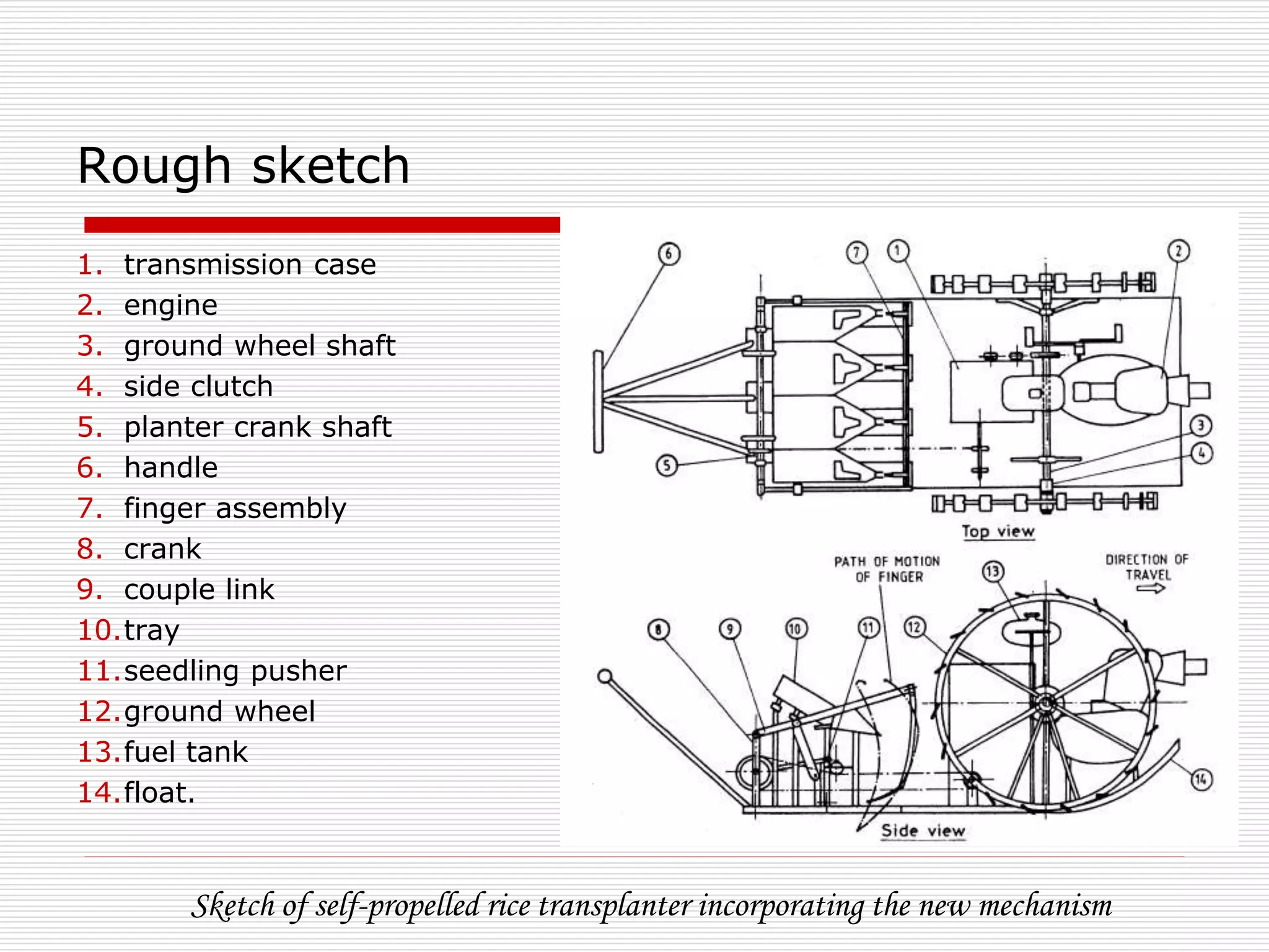
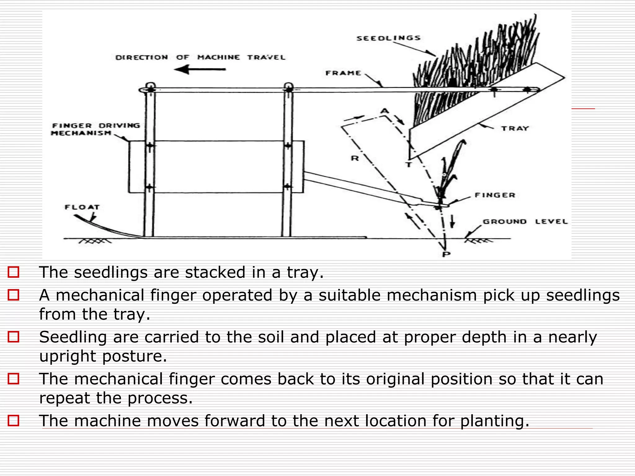
Sketch showing parts of the rice transplanter; mechanical finger for precise seedling placement.
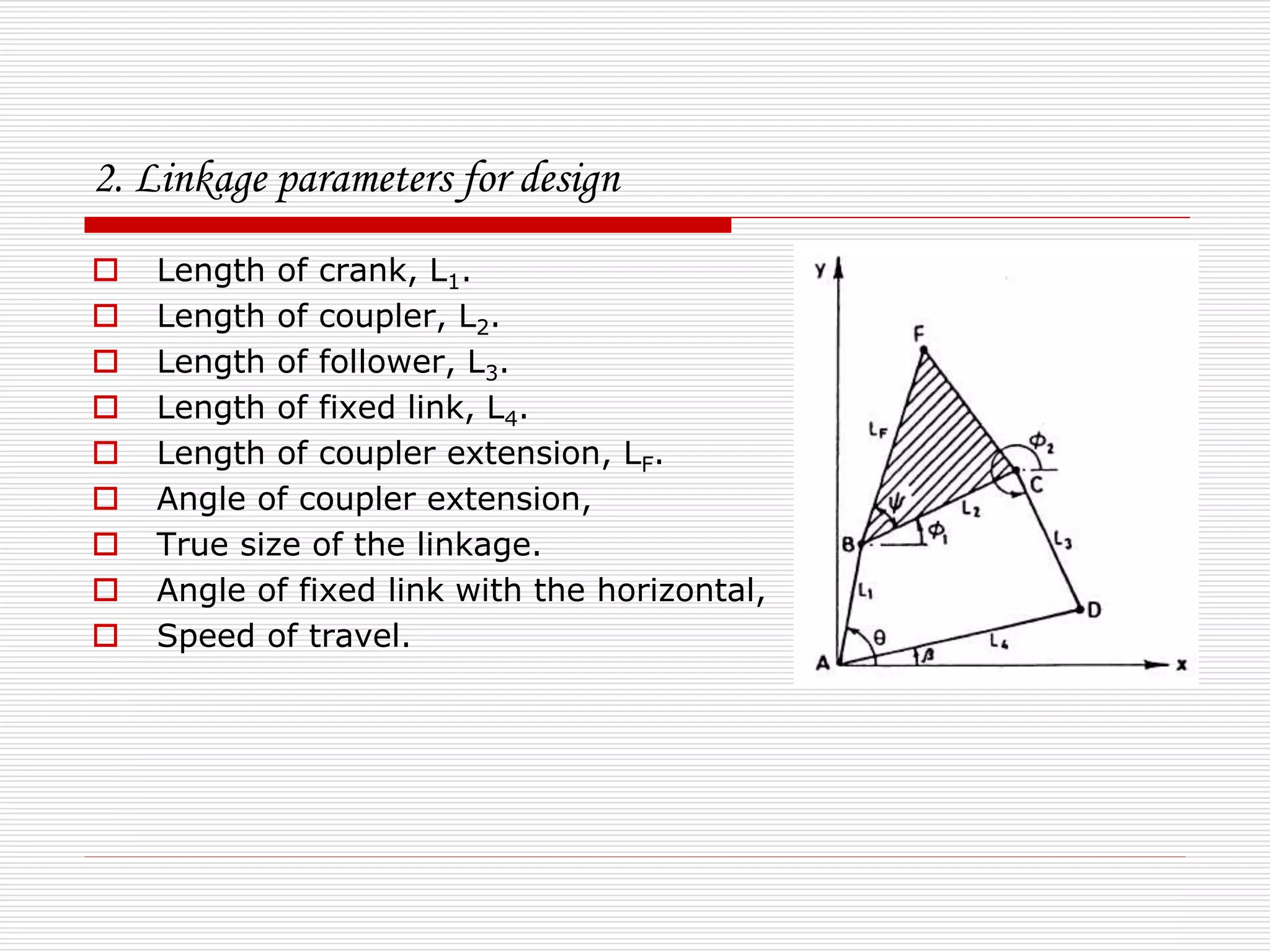
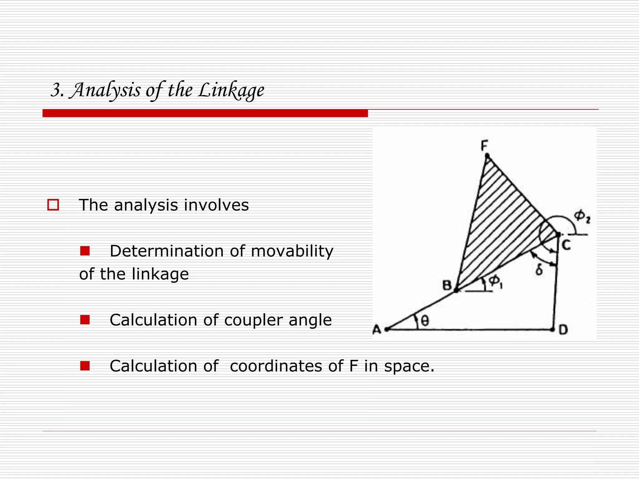
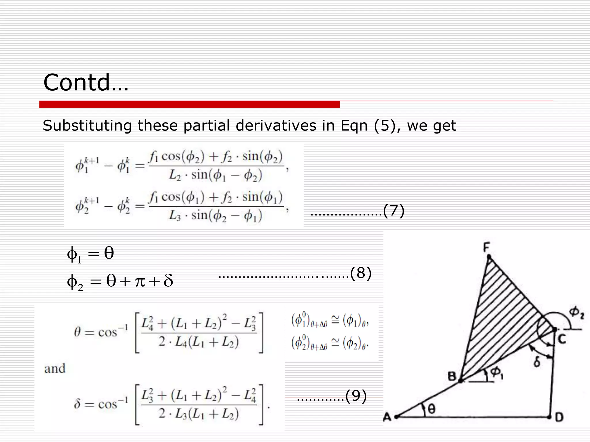
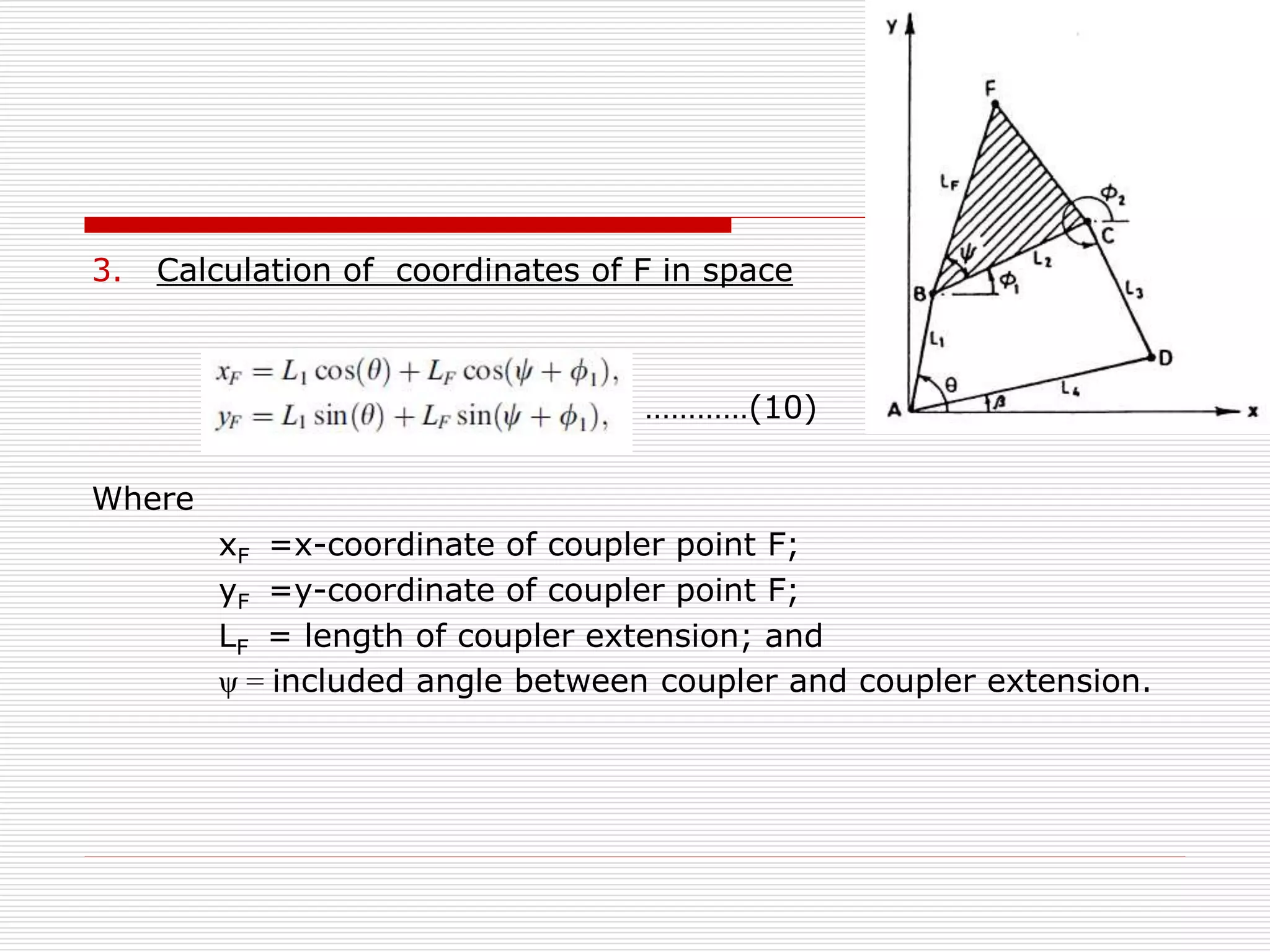
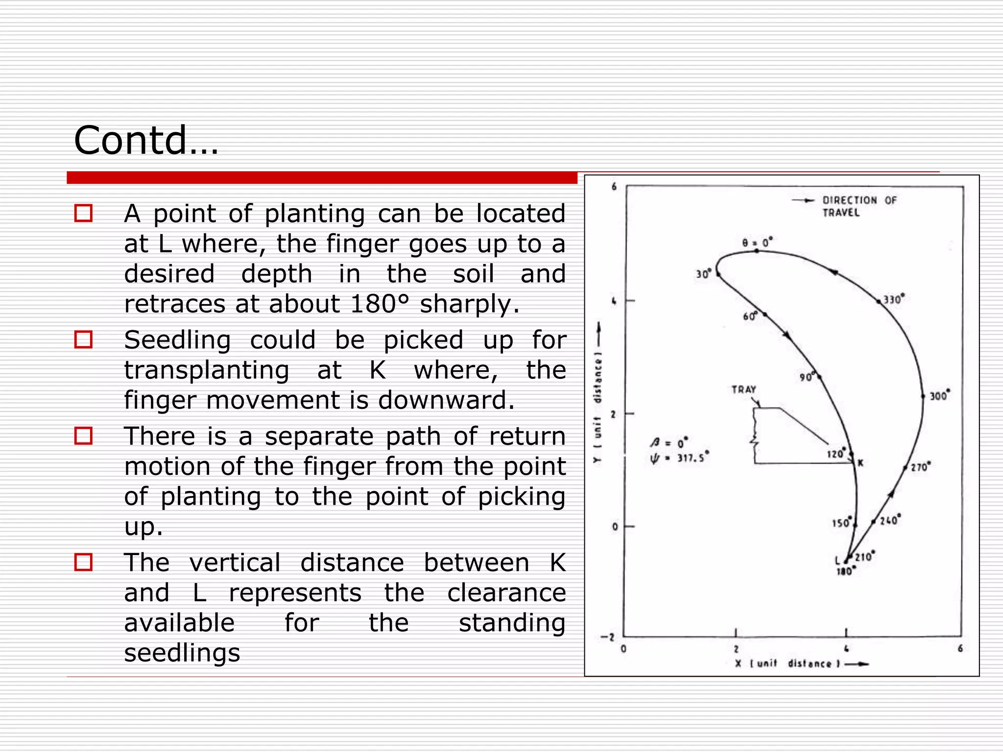
Explanation of motion requirements, linkage parameters, and analysis of the planting mechanism.
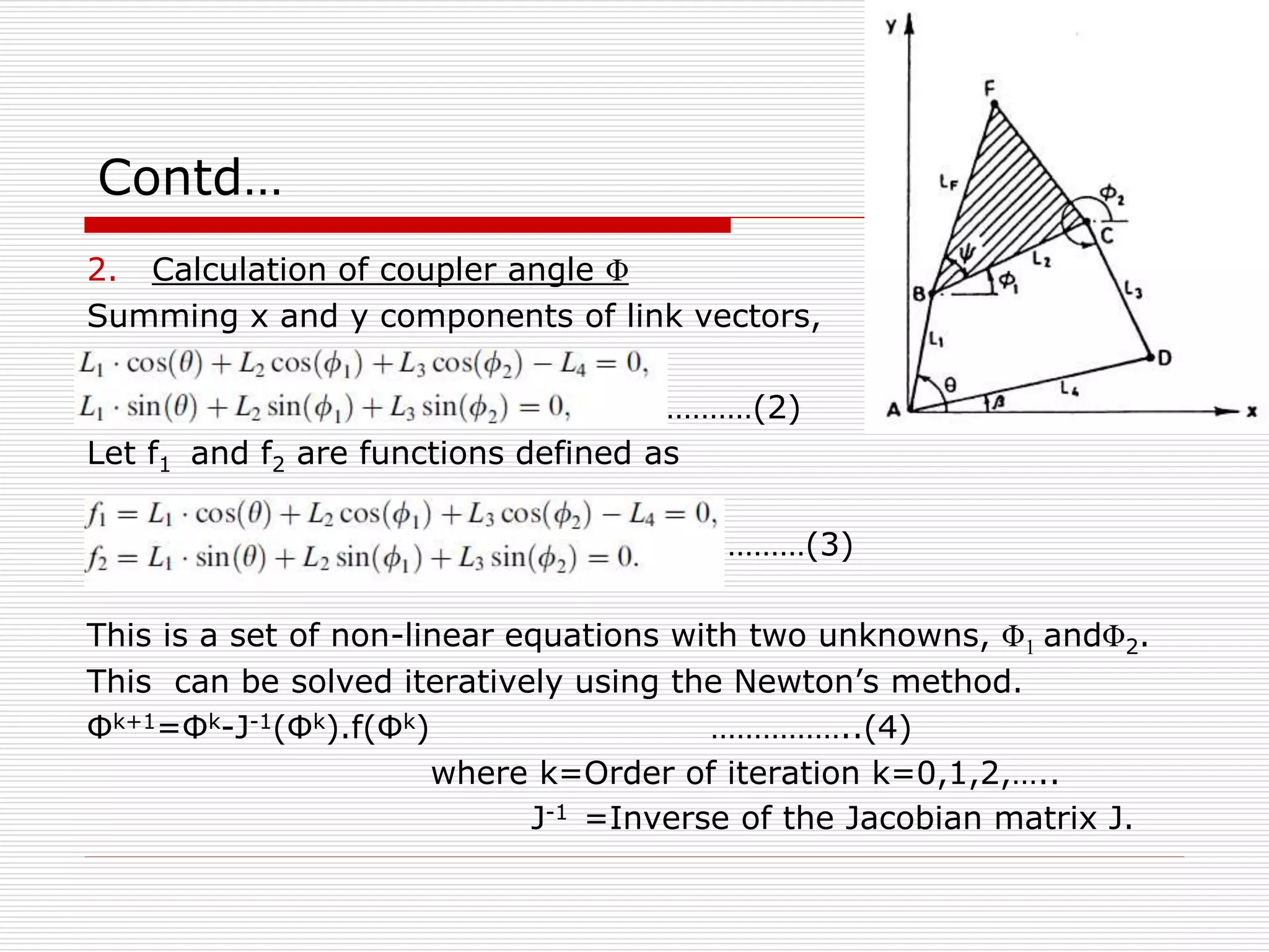
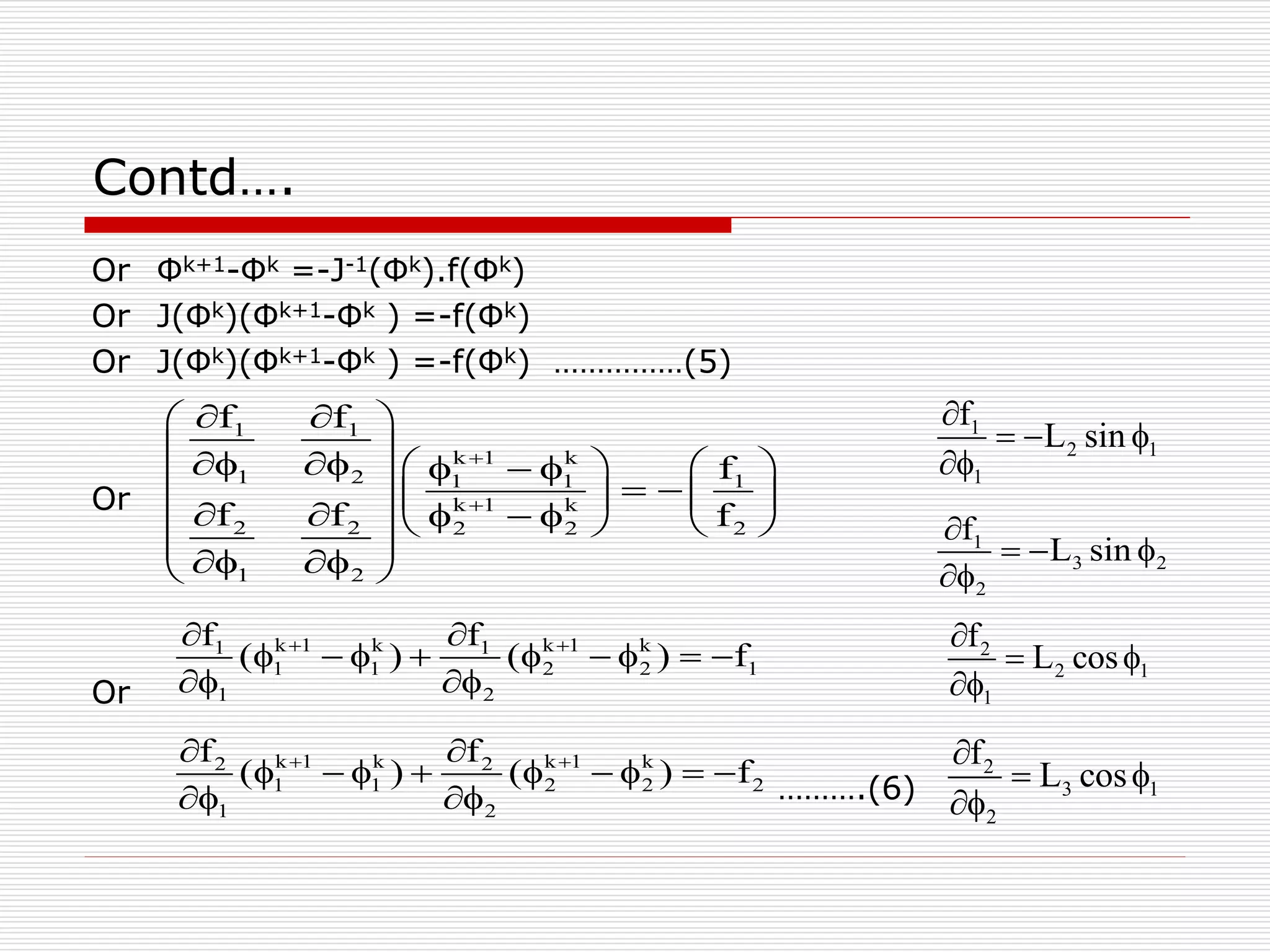
Grashof condition to determine linkage movability; iterative calculations of coupler angles and coordinates.
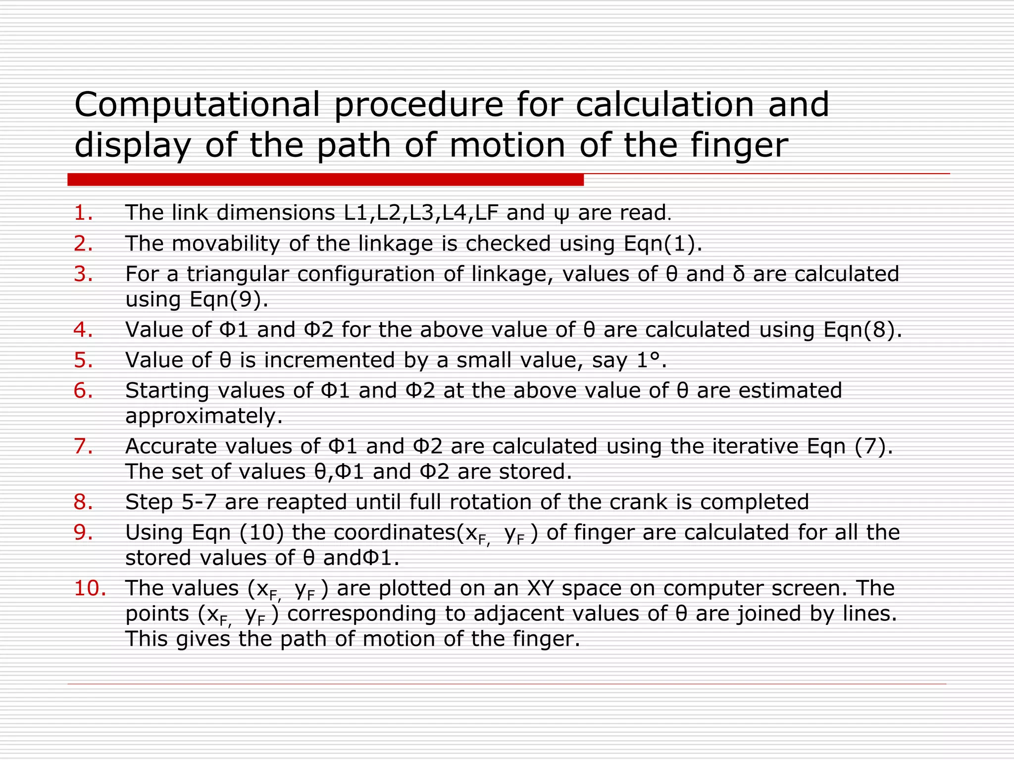
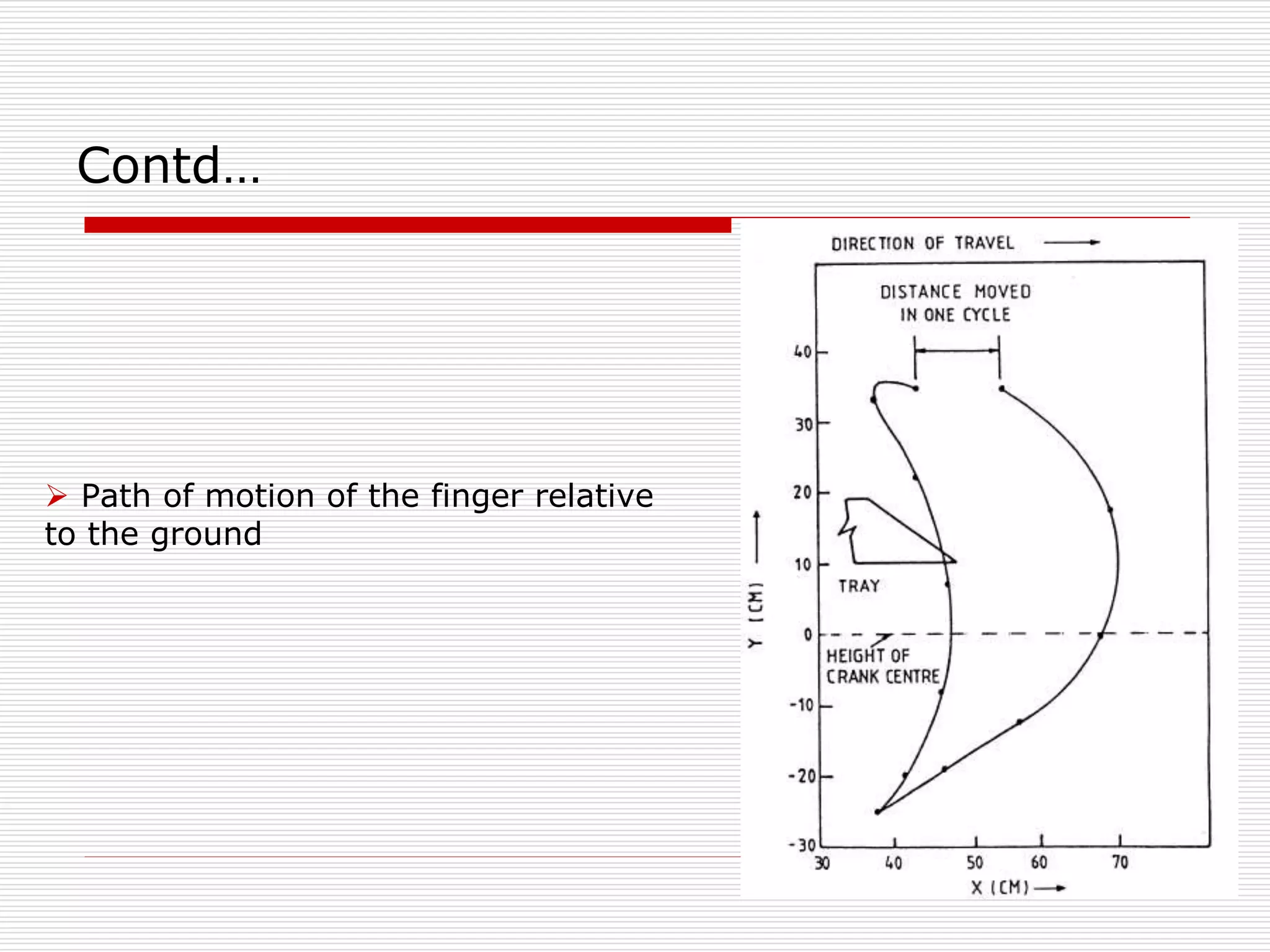
Steps needed to compute and visualize the path of the planting finger during operation.
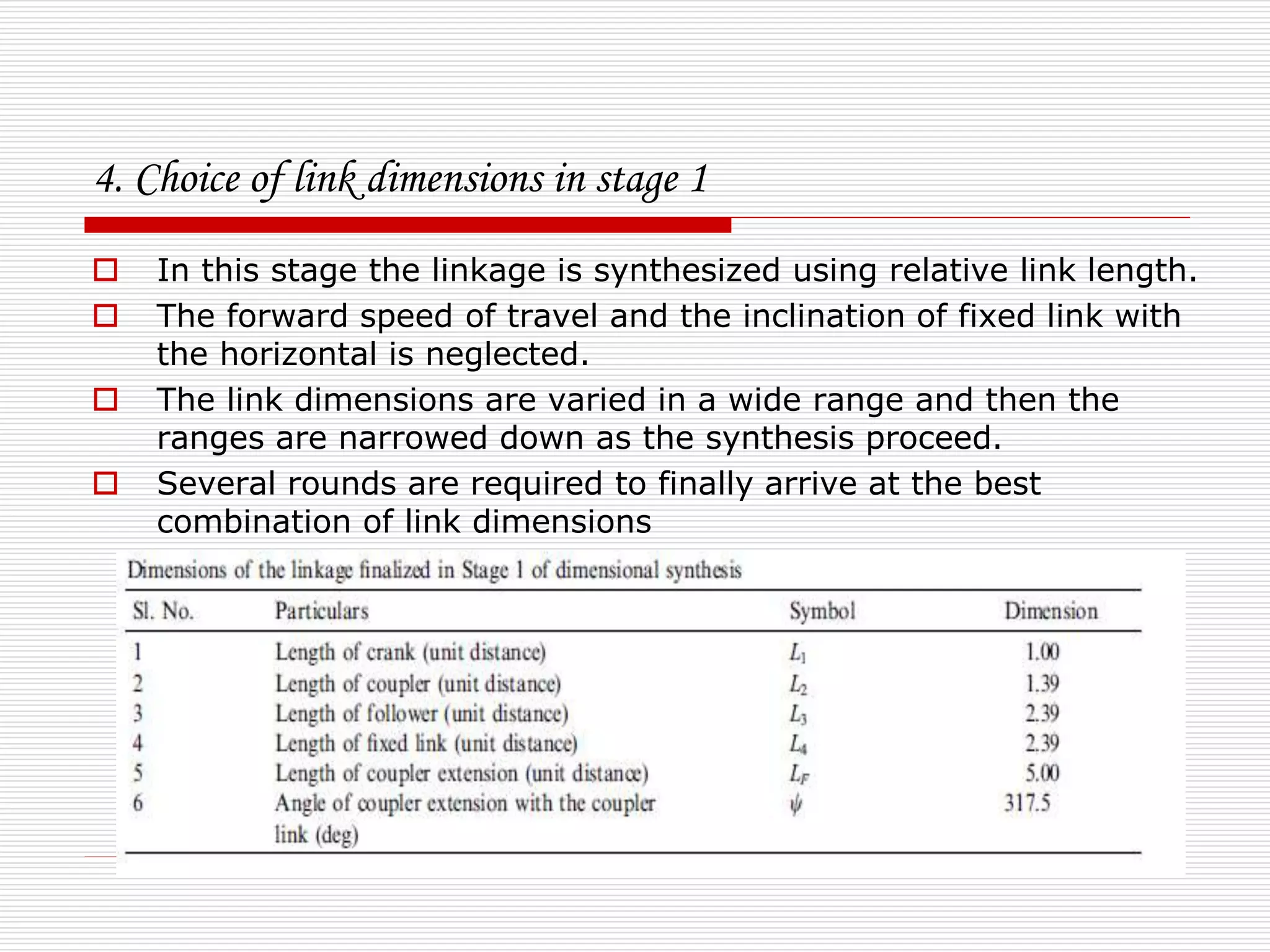
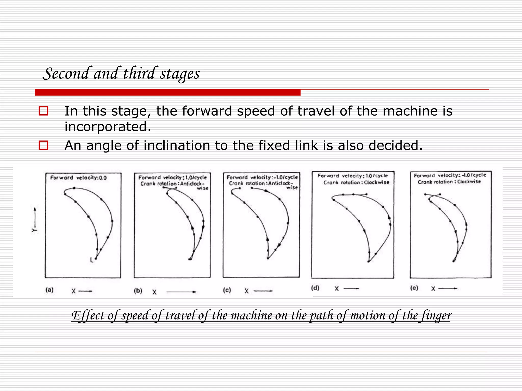
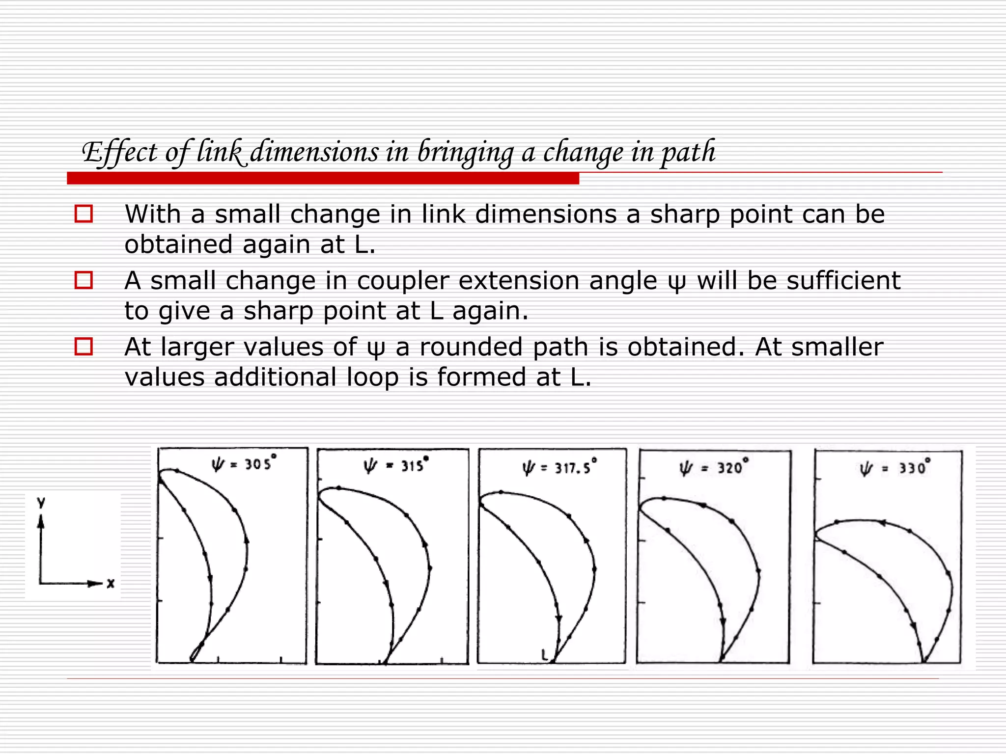
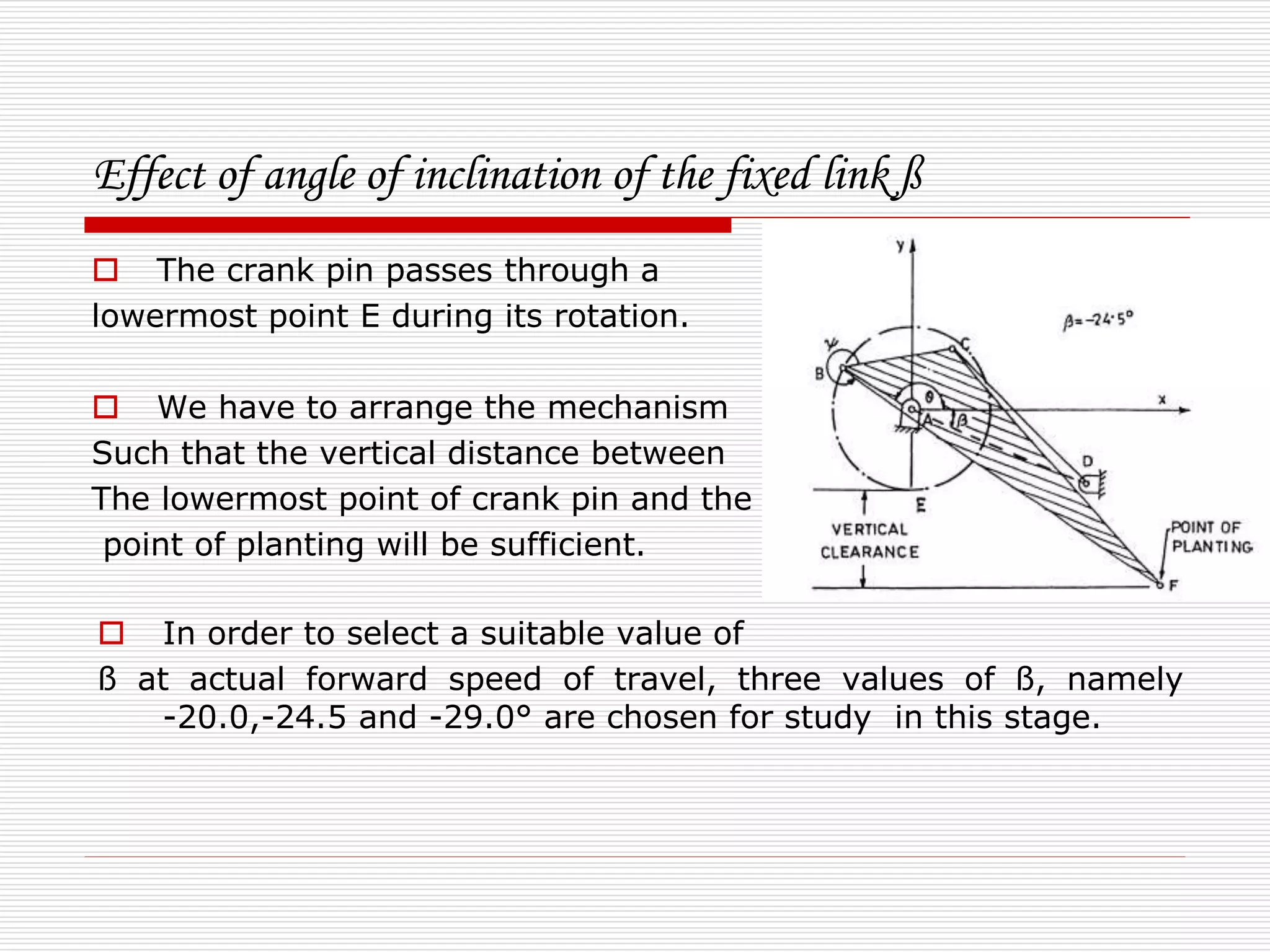
Stages of adapting link dimensions and speed of travel to ensure precise planting and efficient operation.
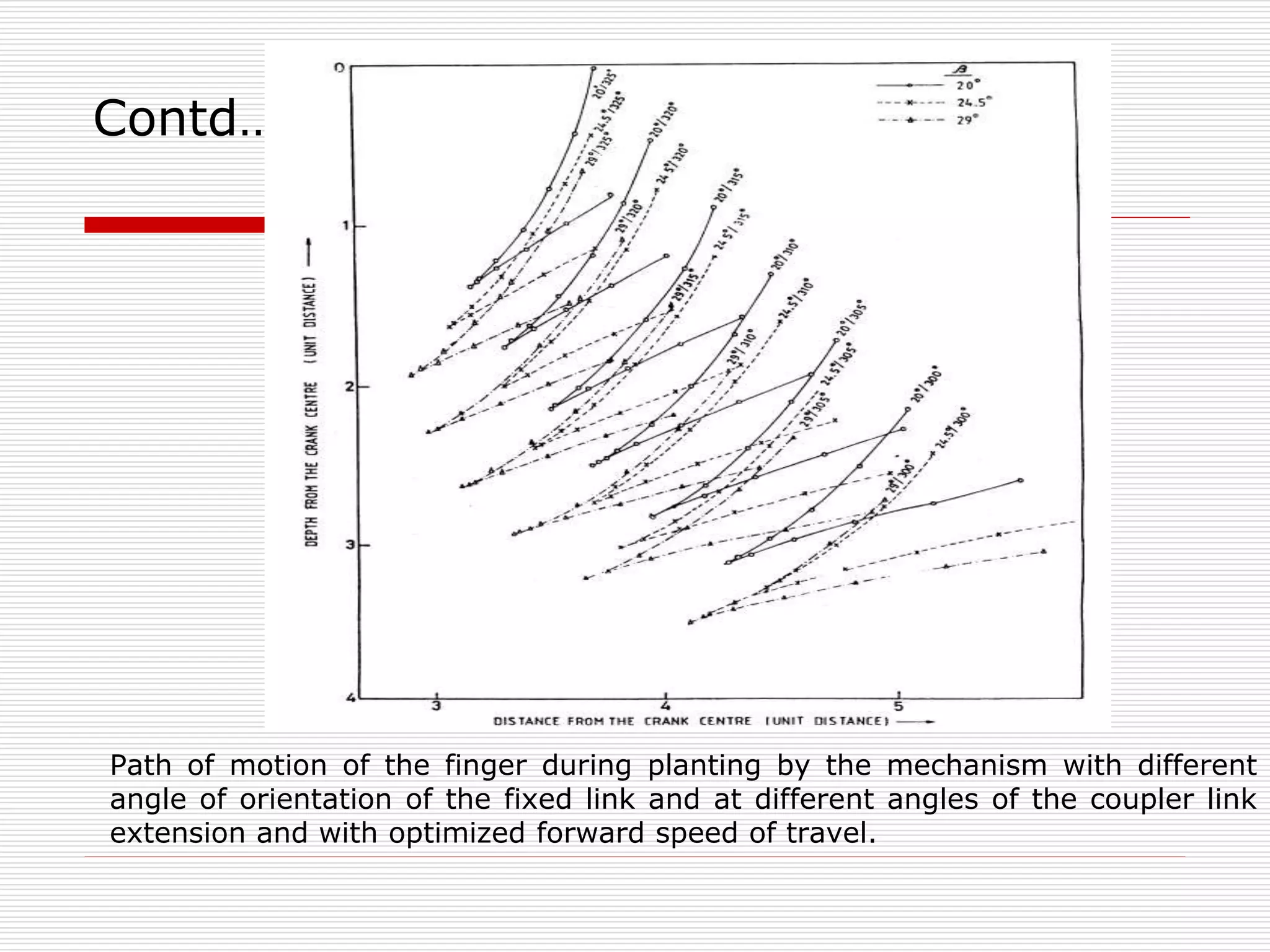
Study of finger motion paths under different conditions to achieve optimal planting outcomes.
Advantages of designed mechanization, including comfort, efficiency, and potential for further enhancements.
List of resources and research materials that informed the development of the rice transplanting mechanism.
Concluding thank you to the audience, summarizing the presentation.