Download to read offline
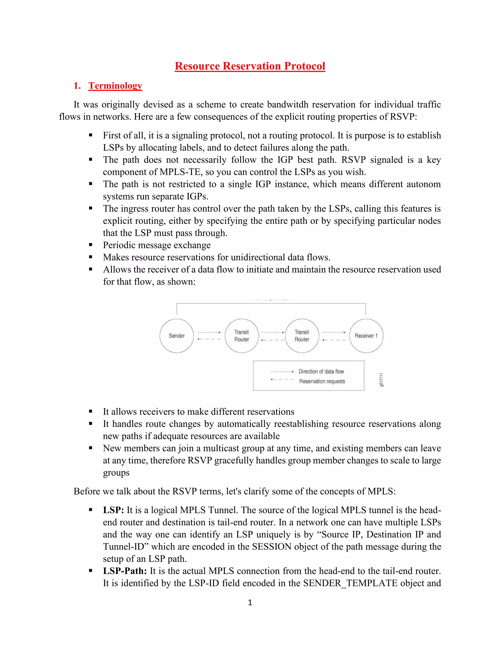


This document discusses the Resource Reservation Protocol (RSVP) and its role in establishing bandwidth reservations for individual traffic flows within networks, primarily focusing on its use in MPLS-TE. It covers key concepts such as LSPs, RSVP messages (path and resv), and the handling of explicit route objects and record route objects to manage the path taken by data flows. Additionally, it provides examples and explanations for configuring RSVP and analyzing label reservations in an MPLS network.