Recent Advances InMobile Robotics A Topalov
download
https://ebookbell.com/product/recent-advances-in-mobile-robotics-
a-topalov-4114804
Explore and download more ebooks at ebookbell.com
2.
Here are somerecommended products that we believe you will be
interested in. You can click the link to download.
Recent Advances In Thin Film Photovoltaics Udai P Singh Nandu B Chaure
https://ebookbell.com/product/recent-advances-in-thin-film-
photovoltaics-udai-p-singh-nandu-b-chaure-45335492
Recent Advances In Distillery Waste Management For Environmental
Safety Vineet Kumar
https://ebookbell.com/product/recent-advances-in-distillery-waste-
management-for-environmental-safety-vineet-kumar-46162998
Recent Advances In Recycling Engineering Proceedings Of The
International Conference On Advances And Innovations In Recycling
Engineering Air2021 N A Siddiqui
https://ebookbell.com/product/recent-advances-in-recycling-
engineering-proceedings-of-the-international-conference-on-advances-
and-innovations-in-recycling-engineering-air2021-n-a-siddiqui-46180886
Recent Advances In Materials Technologies Select Proceedings Of Icemt
2021 K Rajkumar
https://ebookbell.com/product/recent-advances-in-materials-
technologies-select-proceedings-of-icemt-2021-k-rajkumar-46222686
3.
Recent Advances InFluid Dynamics Select Proceedings Of Icaffts 2021
Jyotirmay Banerjee
https://ebookbell.com/product/recent-advances-in-fluid-dynamics-
select-proceedings-of-icaffts-2021-jyotirmay-banerjee-46255666
Recent Advances In Natural Products Science Ahmed Alharrasi
https://ebookbell.com/product/recent-advances-in-natural-products-
science-ahmed-alharrasi-46294700
Recent Advances In Earthquake Engineering Select Proceedings Of Vcdrr
2021 Sreevalsa Kolathayar
https://ebookbell.com/product/recent-advances-in-earthquake-
engineering-select-proceedings-of-vcdrr-2021-sreevalsa-
kolathayar-46347384
Recent Advances In Structural Engineering And Construction Management
Select Proceedings Of Icsmc 2021 Kong Kian Hau
https://ebookbell.com/product/recent-advances-in-structural-
engineering-and-construction-management-select-proceedings-of-
icsmc-2021-kong-kian-hau-46455236
Recent Advances In Electrochemical Promotion Of Catalysis 1st Ed 2023
Philippe Vernoux
https://ebookbell.com/product/recent-advances-in-electrochemical-
promotion-of-catalysis-1st-ed-2023-philippe-vernoux-46461932
free online editionsof InTech
Books and Journals can be found at
www.intechopen.com
9.
Contents
Preface IX
Part 1Visual Perception, Mapping, Robot Localization
and Obstacle Avoidance 1
Chapter 1 3D Visual Information for Dynamic Objects Detection and
Tracking During Mobile Robot Navigation 3
D.-L. Almanza-Ojeda and M.-A. Ibarra-Manzano
Chapter 2 Development of an Autonomous Visual Perception
System for Robots Using Object-Based Visual Attention 25
Yuanlong Yu, George K. I. Mann and Raymond G. Gosine
Chapter 3 Three-Dimensional Environment Modeling Based
on Structure from Motion with Point and Line Features
by Using Omnidirectional Camera 51
Ryosuke Kawanishi, Atsushi Yamashita and Toru Kaneko
Chapter 4 Mobile Robot Position Determination 69
Farouk Azizi and Nasser Houshangi
Chapter 5 Vision Based Obstacle Avoidance Techniques 83
Mehmet Serdar Guzel and Robert Bicker
Chapter 6 Non-Rigid Obstacle Avoidance for Mobile Robots 109
Junghee Park and Jeong S. Choi
Part 2 Path Planning and Motion Planning 125
Chapter 7 Path Planning of Mobile Robot in
Relative Velocity Coordinates 127
Yang Chen, Jianda Han and Liying Yang
Chapter 8 Reachable Sets for Simple Models of Car Motion 147
Andrey Fedotov, Valerii Patsko and Varvara Turova
10.
VI Contents
Chapter 9Neural Networks Based Path Planning
and Navigation of Mobile Robots 173
Valeri Kroumov and Jianli Yu
Chapter 10 Path Searching Algorithms of Multiple Robot
System Applying in Chinese Chess Game 191
Jr-Hung Guo, Kuo-Lan Su and Sheng-Ven Shiau
Chapter 11 Motion Planning for Mobile Robots Via Sampling-Based
Model Predictive Optimization 211
Damion D. Dunlap, Charmane V. Caldwell,
Emmanuel G. Collins, Jr. and Oscar Chuy
Part 3 Mobile Robots Navigation 233
Chapter 12 Fictitious Fuzzy-Magnet Concept in Solving
Mobile–Robot Target Navigation,
Obstacle Avoidance and Garaging Problems 235
Srđan T. Mitrović and Željko M. Ðurović
Chapter 13 Reliable Long-Term Navigation in Indoor Environments 261
Mattias Wahde, David Sandberg and Krister Wolff
Chapter 14 Fuzzy Logic Based Navigation of Mobile Robots 287
Amur S. Al Yahmedi and Muhammed A. Fatmi
Chapter 15 Navigation of Quantum-Controlled Mobile Robots 311
Eugene Kagan and Irad Ben-Gal
Chapter 16 Tracking Control for Reliable Outdoor
Navigation Using Curb Detection 327
Seung-Hun Kim
Part 4 Methods for Control 347
Chapter 17 Statistical Video Based Control of Mobile Robots 349
Krzysztof Okarma and Piotr Lech
Chapter 18 An Embedded Type-2 Fuzzy Controller
for a Mobile Robot Application 365
Leonardo Leottau and Miguel Melgarejo
Chapter 19 LQR Control Methods for Trajectory Execution in
Omnidirectional Mobile Robots 385
Luis F. Lupián and Josué R. Rabadán-Martin
11.
Contents VII
Chapter 20Feedback Equivalence and Control of Mobile Robots Through
a Scalable FPGA Architecture 401
G.P. Moustris, K.M. Deliparaschos and S.G. Tzafestas
Chapter 21 Control Architecture Design and
Localization for a Gas Cutting Robot 427
KiSung You, HwangRyol Ryu and Chintae Choi
13.
Preface
The term roboticswas coined by the science fiction writer Isaac Asimov in 1942, in his
short story Runaround (Astounding Science Fiction) to denote the technological area
addressing the design, construction, operation, and application of robots. The word
robot itself was first introduced to the public by the Czech play writer Karel Čapek in
his play R.U.R. (Rossum’s Universal Robots), published in 1920, and comes from the
Czech word robota, which means “work”. Karel Čapek named his brother - the painter
and writer Josef Čapek - as its actual originator.
There is no single correct definition of robot which seems to satisfy everyone. In fact,
many people have their own definition. According to the Collins Cobuild Dictionary “A
robot is a machine which is programmed to move and perform certain tasks
automatically”. Oxford English Dictionary defines robot as “A machine capable of
carrying out a complex series of actions automatically, especially one programmable
by a computer” or (especially in science fiction) “a machine resembling a human being
and able to replicate certain human movements and functions automatically”.
Various techniques have emerged to develop the science of robotics and robots.
Mobile robots are the focus of a great deal of current research. Mobile robotics is a
young multidisciplinary field involving knowledge from many areas - electrical,
electronics and mechanical engineering, computer, cognitive, and social sciences.
Being engaged in the design of automated systems, it lies at the intersection of artificial
intelligence, computational vision, and robotics. Mobile robots have the capability to
move around in their environment and are not fixed to one physical location.
Contemporary mobile robots are living up to their name more and more. They are no
longer regarded only as mechanisms attached to controls, but represent a combination
of manipulative, perceptive, communicative, and cognitive abilities. Nowadays,
mobile robots are characterized by an increased autonomy and must negotiate the
reality of moving, sensing, and reasoning out their environment. Thanks to the
numerous researchers sharing their goals, visions, and results with the community,
mobile robotics is becoming a very rich and stimulating field.
The book Recent Advances in Mobile Robotics addresses the topic by integrating
contributions from many researchers around the globe. It emphasizes the
computational methods of programming mobile robots, rather than the methods of
14.
X Preface
constructing thehardware. Its content reflects different complementary aspects of
theory and practice, which have recently taken place. The book consists of 21 chapters
which are organized into four major parts:
- Visual Perception, Mapping, Robot Localization, and Obstacle Avoidance
- Path Planning and Motion Planning
- Mobile Robots Navigation
- Methods for Control
The book editor is grateful to the authors for their excellent work and interesting
contributions. Thanks are also due to the prestigious publisher for their editorial
assistance and excellent technical arrangement of the book. We believe that the content
of this book will serve as a valuable handbook to those who work in the research and
development of mobile robots.
October, 2011
Andon V. Topalov
Control Systems Department
Technical University – Sofia, campus in Plovdiv, Plovdiv,
Bulgaria
0
3D Visual Informationfor Dynamic
Objects Detection and Tracking During
Mobile Robot Navigation
D.-L. Almanza-Ojeda* and M.-A. Ibarra-Manzano
Digital Signal Processing Laboratory, Electronics Department; DICIS,
University of Guanajuato, Salamanca, Guanajuato
Mexico
1. Introduction
An autonomous mobile robot that navigates in outdoor environments requires functional
and decisional routines enabling it to supervise the estimation and the performance of all
its movements for carrying out an envisaged trajectory. At this end, a robot is usually
equipped with several high-performance sensors. However, we are often interested in less
complex and low-cost sensors that could provide enough information to detect in real-time
when the trajectory is free of dynamic obstacles. In this context, our strategy was focused
on visual sensors, particulary on stereo vision since this provides the depth coordinate
for allowing a better perception of the environment. Visual perception for robot mobile
navigation is a complex function that requires the presence of "salience" or "evident" patrons
to identify something that "breaks" the continuous tendency of data. Usually, interesting
points or segments are used for evaluating patrons in position, velocity, appearance or other
characteristics that allows us forming groups (Lookingbill et al., 2007), (Talukder & Matthies,
2004). Whereas complete feature vectors are more expressive for explaining objects, here we
use 3D feature points for proposing a strategy computationally less demanding conserving
the main objective of the work: detect and track moving objects in real time.
This chapter presents a strategy for detecting and tracking dynamic objects using a
stereo-vision system mounted on a mobile robot. First, a set of interesting points are extracted
from the left image. A disparity map, provided by a real-time stereo vision algorithm
implemented on FPGA, gives the 3D position of each point. In addition, velocity magnitude
and orientation are obtained to characterize the set of points on the space R6. Groups of
dynamic 2D points are formed using the a contrario clustering technique in the 4D space and
then evaluated on their depth value yielding groups of dynamic 3D-points. Each one of these
groups is initialized by a convex contour with the velocity and orientation of the points given
a first estimation of the dynamic object position and velocity. Then an active contour defines
a more detailed silhouette of the object based on the intensity and depth value inside of the
contour. It is well known that active contour techniques require a highly dense computations.
Therefore, in order to reduce the time of processing a fixed number of iterations is used at
each frame, so the convergence of the object real limits will be incrementally achieved along
*Part of this work was developed when authors were with LAAS-CNRS, Toulouse, France
1
20.
2 Will-be-set-by-IN-TECH
several frames.A simple and predefined knowledge about the most usual dynamic objects
found in urban environments are used to label the growing regions as a rigid or non-rigid
object, essentially cars and people. Experiments on detection and tracking of vehicles and
people, as well as during occlusion situations with a mobile robot in real world scenarios are
presented and discussed.
2. Related works
The issue of moving object detection has been largely studied by the robotic and computer
vision community. Proposed strategies use mainly a combination of active and passive
sensors mounted on the mobile robot like laser (Vu & Aycard, 2009) with cameras (Katz et al.,
2008), or infrared cameras (Matthies et al., 1998), just to name a few. However, a multi-sensor
system requires to solve the problem of fusing the data from different sources which often
requires more complex estimation cases. Indeed, more information could be acquired using
several sensors but these systems are expensive and complex. To overcome those constraints,
the proposed solution consist in using one or more cameras as the only source of information
in the system (Talukder & Matthies, 2004), (Williamson, 1998). Essentially vision sensors
provide enough information for localization and mapping (Sola et al., 2007) or for describing
static and moving objects on the environment (Klappstein et al., 2008).
The stereo-vision is one of the most used techniques for reconstructing the 3D (depth)
information of a scene from two images, called left and right. This information is acquired
from two cameras separated by a previously established distance. The disparity map is
a representation that contains the depth information of the scene. It is well known that
dense stereo-vision delivers more complete information than sparse stereo-vision but this is
a high-processing cost technique which enables to perform in real time using and ordinary
computer system. We use a stereo-vision technique in order to detect moving objects but
implemented on a re-configurable architecture that maximizes the efficiency of the system.
In the last decade, several works have proposed the development of high-performance
architectures to solve the stereo-vision problem i.e. digital signal processing (DSP), field
programmable gate arrays (FPGA) or application-specific integrated circuits (ASIC). The ASIC
devices are one of the most complicated and expensive solutions, however they afford the best
conditions for developing a final commercial system (Woodfill et al., 2006). On the other hand,
FPGA have allowed the creation of hardware designs in standard, high-volume parts, thereby
amortizing the cost of mask sets and significantly reducing time-to-market for hardware
solutions. However, engineering cost and design time for FPGA-based solutions still remain
significantly higher than software-based solutions. Designers must frequently iterate the
design process in order to achieve system performance requirements and simultaneously
minimize the required size of the FPGA. Each iteration of this process takes hours or days
to be completed (Schmit et al., 2000). Even if designing with FPGAs is faster than designing
ASICs, it has a finite resource capacity which demands clever strategies for adapting versatile
real-time systems (Masrani & MacLean, 2006).
2.1 Overall strategy for 3D dynamic object detection from a mobile robot
A seminal work of this strategy was presented in (Almanza-Ojeda et al., 2010)
and (Almanza-Ojeda et al., 2011). Whereas the former proposes a monocamera
strategy (Almanza-Ojeda et al., 2010), and the latter the fusion with the information provided
by inertial (IMU) (Almanza-Ojeda et al., 2011), here we propose an extension of this strategy to
a stereo vision images provided by a bank stereo mounted on the robot. The stereo images are
4 Recent Advances in Mobile Robotics
21.
3D Visual Informationfor Dynamic Objects Detection and Tracking During Mobile Robot Navigation 3
processed by a stereo vision algorithm designed on FPGA that calculates the disparity map
which provides the depth at each point of the input image. Thus, we use a combination of the
3D and 2D representation of feature points for grouping them according to similar distribution
function in position and velocity. Moreover, these groups of points permit us to initialize an
active contour for obtaining the object boundary. Therefore, the contour initialization of the
detected points is fundamental in order to properly perform the shape recovering.
A block diagram of the proposed generalized algorithm is depicted in figure 1. A stereo vision
module for FPGA based on Census Transform provides the disparity map using left and right
images. At the same time, a selection-tracking process of feature points is carried out on
a loop. However, rather than considering both stereo vision images during interest point
selection, we will consider only left image for obtaining these 2D feature points. Further, each
feature point will be associated with a depth value given by the disparity map. At this point
it is necessary to point out that clustering task is performed until a small number of images
have been processed. According to this, clustering module will receive a spatial-temporal set
of points since each feature location and velocity have been accumulated through the time.
The clustering method that we use is the a contrario method proposed by Veit et. al. (Veit
et al., 2007). This clustering method consist in grouping the interesting points which have a
"coherent" movement along a short number of consecutive images. Here the term coherent
refers to movements that follow a similar and constant magnitude and direction described by
the probability density function of the points under evaluation.
Fig. 1. Global strategy of object detection and identification using a stereo vision system
mounted on a mobile robot
Once dynamic group of points have been detected by the clustering process, from this group
of points it is possible to delimit a region and an irregular contour in the image with the aim
of characterizing a probable dynamic object. Thus, by doing an analysis of intensity inside of
this contour, we propose to match the provided region along the image sequence in order to
follow the non-rigid objects that have more complicated movement, like pedestrians.
This work provides two distinct contributions: (1) the addition of depth information for
performing the clustering of 3D set of dynamic points instead of only 2D as in the a
contrario clustering technique (Veit et al., 2007), (2) the use of dynamic groups for initializing
5
3D Visual Information for Dynamic Objects
Detection and Tracking During Mobile Robot Navigation
22.
4 Will-be-set-by-IN-TECH
an irregularcontour active that temporally recovers actual object boundary. The second
contribution was preliminary discussed in (Almanza-Ojeda et al., 2011) where the same active
contour was initialized for representing object region, however that only uses a snake based
on contour information, so nothing is doing with features inside of the region.
The structure of the chapter is as follows. In section 3, we describe the stereo vision module
and its performance. Then section 4.1 details interest 2D point selection and how the 3D points
are obtained using the disparity map. The grouping technique of the interest points based
on the a contrario clustering is explained in section 4.2. We present in section 5 object shape
recovering using active contours. Section 6 contains our experimental results from indoor an
outdoor environments. Finally, we end up with conclusions in section 7.
3. Stereo vision module
We use a disparity map calculated using the Census Transform algorithm (Zabih &
Woodfill, 1994) implemented on a programmable device, in this case a FPGA (Field
Programmable Gate Array). The architecture of the Census transform algorithm was
developed by (Ibarra-Manzano, Devy, Boizard, Lacroix & Fourniols, 2009) in which left and
right images acquired from the stereo vision bank are processed for generating up to 325
dense disparity maps of 640 × 480 pixels per second. It is important to point out that most
of the vision-based systems do not require high video-frame rates because usually they are
implemented on computers or embedded platforms which are not FPGA-based. As this is
also our case, we have adapted the disparity map generation to the real-time application
required by our system by tuning some configuration parameters in the architecture. A block
diagram of the stereo vision algorithm is shown in figure 2. In the following, we will describe
in general the calculation of the disparity map based on the Census transform. However,
the architectural implementation on the FPGA is a problem that has not dealt with in this
work, all these details will be found in (Ibarra-Manzano, Devy, Boizard, Lacroix & Fourniols,
2009), (Ibarra-Manzano & Almanza-Ojeda, 2011).
In the stereo vision algorithm each of the images (right and left) are processed independently
in parallel. The process begins with the rectification and correction of the distortion for
each image in order to decrease the size of the search of points to a single dimension
during disparity calculation. This strategy is known as epipolar restriction in which, once
the main axes of the cameras have been aligned in parallel, founding the displacement of
the position between the two pixels (one per camera) is reduced to search in each aligned
line. That is, if any pair of pixels is visible in both cameras and assuming they are the
projection of a single point in the scene, then both pixels must be aligned on the same epipolar
line (Ibarra-Manzano, Almanza-Ojeda, Devy, Boizard & Fourniols, 2009). Therefore under this
condition, an object location in the scene is reduced to a horizontal translation. Furthermore,
the use of the epipolar restriction allows to reduce the complexity and the size of the final
architecture.
Next, rectified and corrected images are filtered using an arithmetic mean filter. Once input
images have been filtered, they are used to calculate the Census Transform as depicted in
the figure 2. This transform is a non-parametric measure used during the matching process
for measuring similarities and obtaining the correspondence between the points into the
left and right images. A neighborhood of pixels is used for establishing the relationships
among them. From the Census Transform, two images are obtained referred to as ICl and
ICr which represent the left and right Census images. Two pixels extracted from the Census
images (one for each image) are compared using the Hamming distance. This comparison
6 Recent Advances in Mobile Robotics
23.
3D Visual Informationfor Dynamic Objects Detection and Tracking During Mobile Robot Navigation 5
Fig. 2. Block diagram of the stereo vision algorithm (Ibarra-Manzano & Almanza-Ojeda,
2011)
which is called the correlation process allows us to obtain a disparity measure. The disparity
measure comes from the similarity maximization function in the same epipolar line for the
two Census images. The similarity evaluation is based on the binary comparison between
two bit chains calculated by the Census Transform. The correlation process is carried out two
times, (left to right then right to left) with the aim of reducing the disparity error and thus
complementing the process. Once both disparity measures have been obtained, the disparity
measure validation (right to left and left to right) consists of comparing both disparity values
and obtaining the absolute difference between them. Before delivering a final disparity image,
a novel filtering process is needed for improving its quality. In this final stage, the use of a
median spatial filter was found more convenient.
3.1 Disparity map acquired in real time
The final architecture for executing the stereo vision algorithm based on the Census Transform
was developed using the level design flow RTL (Ibarra-Manzano, Devy, Boizard, Lacroix
& Fourniols, 2009). The architecture was codified in VHDL language using Quartus II
workspace and ModelSim. Finally, it was synthesized for an EP2C35F672C6 device contained
in the Cyclone IV family of Altera. Table 1 lays out some of the configuration parameters
used during the disparity map computation exploited during the dynamic object detection
and tracking approach. We would like to highlight that disparity image is computed through
the time with a high performance of 30 image per second although detection and tracking
7
3D Visual Information for Dynamic Objects
Detection and Tracking During Mobile Robot Navigation
24.
6 Will-be-set-by-IN-TECH
approach doesnot reach this performance. More technical details about the implementation
are discussed in section 6.
Parameter Value
Image size 640 × 480
Window size 7 × 7
Disparity max 64
Performance 40
Latency (μs) 206
Area 6, 977
Memory size 109 Kb
Table 1. Configuration parameters of the Stereo vision architecture.
The architecture was tested for different navigational scenes using a stereo vision bank, first
mounted in a mobile robot and then in a vehicle. In the following, we will describe the
obtained results for two operational environments. Figure 3 shows the left and right images
acquired from the bank stereo and the associated disparity image delivered by the stereo
vision algorithm. Dense disparity image depicts the disparity value in gray color levels in
figure 3 (c). By examining this last image, we can determine that if the object is close to
the stereo vision bank that means a big disparity value, so it corresponds to a light gray
level. Otherwise, if the object is far from the stereo vision bank, the disparity value is low,
which corresponds to a dark gray level. In this way, we observe that the gray color which
represents the road in the resulting images gradually changes from the light to dark gray
level. We point out the right side of the image, where we can see the different tones of gray
level corresponding to the building. Since large of the building is located at different depths
with respect to the stereo vision bank, in the disparity map corresponding gray color value is
assigned from lighter to darker gray tones.
(a) Left image (b) Right image (c) Result from FPGA
implementation
Fig. 3. Stereo images acquired from a mobile robot during outdoor navigation: a) left image
b) right image and c) the disparity map.
In the second test (see figure 4), the stereo vision bank is mounted on a vehicle that is driven
on a highway. This experimental test results in a difficult situation because the vehicle is
driven at high-speed during the test. Furthermore, this urban condition requires a big distance
between both cameras in the stereo vision bank with the aim of augmenting the field of view.
A consequence of having a big distance between the two cameras is represented in figure 4 (a)
and (b) in which, while the left image show a car that overtakes our vehicle, this car is out of
8 Recent Advances in Mobile Robotics
25.
3D Visual Informationfor Dynamic Objects Detection and Tracking During Mobile Robot Navigation 7
sight in the right camera. Therefore, the dense disparity map shown in figure 4 (c) does not
display a cohesive depth value of the vehicle due to mismatches in the information between
both images. Nevertheless, we highlight all the different depths represented by the gray color
value in the highway that gradually turns darker until the black color which represents an
infinity depth.
(a) Left image (b) Right image (c) Result from FPGA
implementation
Fig. 4. Stereo images acquired from a vehicle in the highway: a) left image b) right image and
c) the disparity map.
4. Moving features perception and grouping
4.1 Active 3D point selection
When dealing with vision-based approaches, the problem of processing a large quantity of
information requires that the system resources be sophisticated and expensive if we want to
get a real time performance. As we work with left and right images from the stereo vision
bank, processing both images yields to more information about the scene but has also more
computation requirements. To overcome this problem, we consider to deal with a sparse
set of features resulted by the analysis of the left image that represents the most significant
and salience feature points in all the image. We use this sparse proposition because it is
important to distribute time of processing among some others essential tasks of the strategy,
therefore feature selection process must expend minimal time. For the feature point selection,
we use the Shi-Tomasi approach (Shi & Tomasi, 1994). This approach consists in providing
the most representative points based on image gradient analysis, i.e. corners, borders, and all
the regions with high contrast change. Figure 5 depicts both image gradients in horizontal
and vertical directions of an input image in gray color level, from which N best features
are selected for describing image content. In particular, this input image has high content
of information, therefore, a larger number of points have to be selected in accordance with
image-density information. Furthermore, the number N is restricted by the time of processing
required for reaching real-time performance. According to this, the number of points does not
have to exceed N = 180. Once 2D’s interesting points have been selected on the left image
and the disparity map for the stereo-images computed, obtaining the 3D characterization of
the points is straightforward. Each 2D point is associated with a corresponding depth value
provided by the disparity image to conform the 3D point representation.
Until now, we have obtain a set of 2D features on the left image at time t and their
corresponding 3D characterization. For each feature, displacement vectors are computed
through the time by using the Kanade-Lucas-Tomasi tracker, referred to as the KLT
9
3D Visual Information for Dynamic Objects
Detection and Tracking During Mobile Robot Navigation
26.
8 Will-be-set-by-IN-TECH
(a) Imagegradients
(b) N best features selected
Fig. 5. Image processing for the best interest point selection. a) Gradients in vertical and
horizontal direction of the above input image. b) Green points represent the N best
interesting features resulted by the gradient image analysis.
technique (Shi & Tomasi, 1994), (Lucas & Kanade, 1981). These displacement vectors are used
to calculate feature velocities. We are interested in the accumulation of previous position and
velocity of the points in order to establish a trail of motion. An example of the accumulation
point positions for N initial features detected appears in figure 6. Note that, while most of
the points are distributed in all the image, a small set of points horizontally aligned can
be remarked on the left side of the figure c). These points represent the front part of the
vehicle that enters into the field of view of our robot. Once a short number of images have
been processed, the accumulated vector displacements and positions of the feature points
are evaluated in order to find significant patterns of motion that possibly represent dynamic
objects in the scene. A new feature selection task is carried out, as indicated in the green block
of figure 1. Further, in the case that any dynamic group of points is found, this information
will initialize in the second stage of our strategy, that is the object characterization (right
rectangular box in figure 1).
10 Recent Advances in Mobile Robotics
27.
3D Visual Informationfor Dynamic Objects Detection and Tracking During Mobile Robot Navigation 9
In the following, we explain the a contrario method used for clustering position and velocity
of the points that possibly describe a mobile object.
(a) First image of the tracking (b) Last image of the tracking (c) Accumulate position
through 4 images
Fig. 6. N feature points initially detected at image a) are tracked through 4 images. Image b)
displays the last image during the tracking task. Image c) depicts all the accumulate
positions for the N initial points detected calculated by the tracking process.
4.2 Clustering of 3D points cloud
At this point, we have a distributed set of 2D feature points characterized by their position and
velocity that have been tracked through a short number of consecutive images. Alternatively,
we associated each feature with their corresponding depth position which allows us to
manage with a 3D-data set. Following with the global diagram in figure 1, clustering of
feature points is the next task to carry out. In order to do that, we use the a contrario clustering
method proposed in (Veit et al., 2007). This algorithm is based on the Gestalt theory that
establishes which groups could be formed based on one or several common characteristics
of their elements. In accord to this statement, the a contrario clustering technique identifies
one group as meaningful if all their elements show a different distribution than an established
background random model. Contrary to most clustering techniques, neither initial number of
clusters is required nor parameter have to be tuned. These characteristics result very favorable
in an unknown environment context where the number of resulted clusters have not been
predefined.
In this section we summarize some important concepts of the a contrario clustering method,
used to group feature points. A detailed description of the method derivation is available
in (Desolneux et al., 2008), (Desolneux et al., 2003), (Cao et al., 2007).
4.3 A contrario algorithm description
As we mentioned above, a distribution model for the background has to be defined for
comparing with the associated distribution of the set of points, here referred to as V(x, y, v, θ)
in R4. In this work, we use the background model proposed in (Veit et al., 2007) which
establishes a random organization of the observations. Therefore, background model
elements are independent identically distributed (iid) and follow a distribution p. The iid
nature of random model components proposes an organization with non coherent motion
present.
Next, given the input vector V(x, y, v, θ) from the KLT process (section 4.1), the first objective
is to evaluate which elements in V shows a particular distribution contrary to the established
distribution p of the background model (that explains "a contrario" name). To overcome
11
3D Visual Information for Dynamic Objects
Detection and Tracking During Mobile Robot Navigation
28.
10 Will-be-set-by-IN-TECH
(a) Pointdetection
(b) Position graph (c) Polar velocity graph
Fig. 7. Best fit region search. An initial set of points is selected and tracked in an indoor
environment displayed in image a). The accumulated locations and velocities of the points
are analyzed in order to find the region of points with NFA (G) ≤ 1.
the problem of point by point evaluation, V(x, y, v, θ) is divided in testing groups with
different size of elements using a single linkage method. This method constructs a binary
tree where each node represents a candidate group G. Once a different group of points have
been established, these will be evaluate using a set of given regions represented by H. This
set of regions is formed by a different size of hyper-rectangles that will be used to test the
distribution of each data group in G. An example of groups distribution evaluation is depicted
in figure 7. Each region H ∈ H is centered at each element X ∈ G to find the region HX that
contains all the elements in G and at the same time this region has to minimize the probability
of the background model distribution. This procedure requires that sizes of hyper-rectangles
be in function of data range, in our experiments we use 20 different sizes by dimension. The
measure of meaningfulness (called Number of False Alarms NFA in referenced work) is given
by eq 1.
12 Recent Advances in Mobile Robotics
29.
3D Visual Informationfor Dynamic Objects Detection and Tracking During Mobile Robot Navigation 11
NFA (G) = N2
· |H| min
X ∈ G,
H ∈ H,
G ⊂ HX
B (N − 1, n − 1, p (HX)) (1)
In this equation N represents the number of elements in vector V, |H| is the cardinality of
regions and n is the elements in group test G. The term which appears in the minimum
function is the accumulated binomial law, this represents the probability that at least n
points including X are inside the region test centered in X (HX). Distribution p consist of
four independent distributions, one for each dimension data. Point positions and velocity
orientation follow a uniform distribution because object moving position and direction is
arbitrary. On the other hand, velocity magnitude distribution is obtained directly of the
empirically histogram of the observed data. So that, joint distribution p will be the product of
these four distributions. A group G is said to be meaningful if NFA (G) ≤ 1.
Furthermore two sibling meaningful groups in the binary tree could be belong to the same
moving object, then a second evaluation for all the meaningful groups is calculated by Eq. 2.To
obtain this new measure, we reuse region group information (dimensions and probability)
and just a new region that contains both test groups G1 and G2 is calculated. New terms are
N = N − 2, number of elements in G1 and G2, respectively n
2 = n1 − 1 and n
2 = n2 − 1, and
term T which represents the accumulated trinomial law.
NFAG (G1, G2) = N4
· |H|2
T
N
, n
1, n
2, p1, p2
(2)
Both mesures 1 and 2 represent the significance of groups in binary tree. Final clusters are
found by exploring all the binary tree and comparing to see if it is more significant to have
two moving objects G1 and G2 or to fusion it in a group G. Mathematically, NFA(G)
NFAG(G1, G2) where G1 ∪ G2 ⊂ G. A descriptive result is provided in figure 8. Here blue
points correspond to those that could be dynamic but without a well defined motion, so they
are associated with the background. On the other hand, green points represent the group
in G which shows a different distribution than the random background model. Notice that
graph c) displays polar velocity considering magnitude in X-axis and orientation in Y-axis,
from there, green point positions are not together because they have orientations among 5◦
and 355◦ Further, these points correspond to the vehicle entering on the right side of the image
b).
4.4 Depth validation
As previously mentioned, the 3D characterization of points is achieved using the depth value
described in the disparity map for each two dimensional feature point. From previous section,
a set of dynamic points have been obtained using the clustering process, however this process
was performed considering uniquely 2D points. Thanks to the disparity map, we know the
depth of each feature in dynamic group, so it is possible to perform a second evaluation
looking for similarity in their depths. This depth evaluation is computed in a formally
analogous way to that of the a contrario clustering. However in this case, the number of regions
for testing is considerably reduced since the group of points is already detected in a defined
region, so it is only need the evaluation of similar depths of the points around that region
avoiding the best region search. Additionally, there is not an associated velocity in Z-axis
direction which reduces from hyper-rectangle regions to 3D boxes. Namely x and y denote
the point location in the image and z denotes the disparity value.
13
3D Visual Information for Dynamic Objects
Detection and Tracking During Mobile Robot Navigation
30.
12 Will-be-set-by-IN-TECH
(a) Initialimage (b) Final image
(c) Position points (d) polar-velocity points
Fig. 8. Clustering results after processing 5 consecutive images. a)First image used for feature
selection, b) Last image used for obtaining the trails of the points. A unique dynamic group
of points is detected (green points) for whose graph c) depicts their position and graph d)
their velocity and orientation.
In the next section, we explain how an irregular contour is initialized using the groups of
points calculated by the a contrario clustering, therefore used for passing from a dynamic set
of points to actual object boundary.
5. Object characterization by an active contour
Active models have been widely used in image processing applications, in particular for
recovering shapes and the tracking of moving objects (Li et al., 2010), (Paragios Deriche,
2005). An active contour or snake is a curve which minimizes energy from restrictive external
and internal forces in the image, typically calculated from edges, gradient, among others.
Essentially, a snake is not thought of to solve the problem of automatic search for prominent
contours of the image, but rather for recovering the contour of a form, from an initial position
proposed by other mechanisms. That is to say, if the initial contour is relatively close to the
solution (for example a contour defined manually by an operator or obtained through any
other method), the contour evolves up until minimizing the function of energy defined from
the internal and external forces.
One of the main objectives of this work is to track all mobile objects detected without any prior
knowledge about object type that one follows. In a real and dynamic context, we expect to
find rigid and non rigid mobile objects ie. vehicles, persons. We have shown in section 4.2 the
good performance of the a contrario method for finding initial sets of dynamic points which
correspond to the mobile objects in the scene. However, whereas clustering process deals
14 Recent Advances in Mobile Robotics
31.
3D Visual Informationfor Dynamic Objects Detection and Tracking During Mobile Robot Navigation 13
with feature points, here we describe a strategy for recovering the deformable shape of the
objects through the time by considering others features like intensity image gradient inside
of contour. Therefore, through this section we will describe fundamental details of the active
contours theory, and the object tracking procedure by means of the active contours.
5.1 Active contour initialization
The results obtained in section 4.2 allow the definition of an initial irregular contour that
contains totally or partially our interest object. To this end, we take an outer location of points
in the detected group for initializing an active contour which delimits the object on the image.
An example is displayed in figure 9 1: in image (a) a set of points dynamic (in blue) is detected
on which correspond to the person in motion on this sequence. From this set of points we
have selected those illustrated in color magenta to describe the object contour depicted in
yellow. Due to the fact these points are the most farthest from the center then they are the
most representative and closest to the object frontiers. For the results show in image 9(a), we
have 8 points on the curve and we use for each 4 control points. The value of 4 control points
is fixed for each point on the frontier in order to introduce the corners or discontinuities in the
curve (Marin-Hernandez, 2004). Initial contour will allow us to obtain a deformable model by
a bounded potential shown in figure 9(b). The zone occupied by the object (represented in red
color) is separated from the background. The most intens tones inside of the object are used
to best adapt initial contour to the actual object silhouette. Therefore, a more detailed object
shape is achieved by analyzing internal and external energy in a bounding box that contains
the initial contour.
(a) Initial contour of a non-rigid
object
(b) energy functional
Fig. 9. Test performed with real images acquired by a fixed camera in an indoor
environment. a)Initial contour derived from points further away from the center b) Energy
functional that concentrates internal and external energy considering the initial contour of a).
5.1.1 Parametric active contours.
At this point, it is necessary to represent the initial contour in 9 by a parametric curve u(τ) =
(x(τ), y(τ)), τ ∈ [0, 1], with u(0) = u(1). this contour is deformed through the time domain
to minimize the energy expressed by:
1 This image sequence was downloaded from the web site (Fisher, 2011) provided by EC Funded
CAVIAR project/IST 2001 37540
15
3D Visual Information for Dynamic Objects
Detection and Tracking During Mobile Robot Navigation
32.
14 Will-be-set-by-IN-TECH
Esnake =
1
0
[Eint(u(τ)) + Eext(u(τ))] dτ (3)
where Eint is expressed by two main terms, the first one refers to the elasticity and the second
the flexibility, given:
Eint = α
1
0
|uτ(τ)|2
dτ + β
1
0
|uττ(τ)|2
dτ (4)
τ and ττ indexes in the term u(τ) implies respectively first and second order of derivation.
By returning to the equation 3 for defining the term Eext or the energy of the image (Sekhar
et al., 2008), as the field of potential P:
Eext =
1
0
P(u(τ))dτ (5)
The potential includes different terms defined from image proprieties like edges, lines, etc.
Edges energy is obtained by computing the magnitude of the gradient intensity |∇I|. Without
a good initialization, the energy of the edges will not be enough to locate the objects on
noisy or low contrast images. Therefore an additional potential of the regions is added to
the edge energy. Generally, the potential of the regions is defined by the mean (μ) and the
variance (σ2) of the pixels intensity in the region. However, other constraints could be added
like the object velocities, or other statistics derived from region characteristics (Brox et al.,
2010). Because of the real-time constraints, we calculate only some statistics in the region that
describe the object, such as the main properties to its implementation in correspondence to
the next image. The following section describes the proposed strategy about shape recovering
and object tracking using active contours.
5.2 Incremental silhouette definition
We have tested a method based on the work of Chan and Vese (Chan Vese, 2001) in order
to find the silhouette of the object. In this work, the authors give a region of initialization
which may contain total or partially the object. The analysis of this initial contour will allow
evaluation of the conditions of the energy minimization inside and outside of the contour.
An example of a shape recovering of a person in an indoor environment using the Chan and
Vese method is shown in figure 10. First row of images display the contour evolution. In the
second row the region inside of the contour for each corresponding above image is illustrated.
These images are given as input to the process for recovering real object contour. Furthermore,
white regions on these images are labeled as occupied locations which avoid the detection of
new interesting points inside of it through the time. According to this, new feature selection
(detailed in section 4.1) will look for unoccupied locations in the image allowing the detection
of incoming objects.
Once a partial contour at image t in figure 10 has been obtained by minimizing eq. 3, we
estimate its position at image t + 1 for starting a new convergence process. The prediction
of the region on the next image is always given by the Kalman filter. The vector state of our
object is expressed as:
x0 =
x̄, ȳ, v̄x, v̄y
T
(6)
Namely, x̄, ȳ denote the barycenter location and v̄x, v̄y the means of velocity vector in X
and Y direction respectively. Figure 11 illustrates an example of the filter prediction. The
barycenter position and the partial converged contour are located in accordance with Kalman
16 Recent Advances in Mobile Robotics
33.
3D Visual Informationfor Dynamic Objects Detection and Tracking During Mobile Robot Navigation 15
(a) Initial snake at
image t0
(b) 30 iterations at
image t0
(c) Image t0 + 2 (d) Image t0 + 4
(e) Initial mask at image
t0
(f) Mask at image t0 (g) Mask at image t0 + 2 (h) Mask at image t0 + 4
Fig. 10. Results of the detection and tracking of a non-rigid dynamic object, in this case a
pedestrian on the same sequence of figure 9. Here, we have processed 5 consecutive images,
executing 30 iterations per image in order to find the actual object shape.
filter prediction. We always consider a velocity constant model and the vector state is obtained
from model object displacement. However, in some cases it is first necessary to tune the initial
parameters of the filter because there may exist different types of object movements producing
an undesired acceleration of the predicted position.
5.3 Object contour validation
The difficulties rising from our proposed strategy points out the sensitivity of the active
contours to small discontinuities on the object edges with low-contrast because the energy
is configured over the entire image. To overcome these difficulties we evaluate the disparity
inside of the region corresponding with the binary mask (that will be presented in the next
section figure 15). This evaluation consists in ordering in an ascendant way all the disparity
values inside the region designed by the binary mask then we uniquely consider the median
of the values. In particular, we consider a valid point of the object region if its disparity value
is located up to the 4th percentil in the ordered list (here referred to as 4p). It follows that our
statistical validation for object contour refining can be written as:
M =
1 depth ≥ 4p
0 otherwise
(7)
where M represents the binary mask. It is important to remark that the depth value is the
inverse value of the disparity therefore in this case the fact of rejecting points located on
the first four percentiles represents that these values have a lower disparity value, that is,
disparity values of the background points are expecting to be low. This constrain allow us to
develop a last validity evaluation for obtaining a most detailed and accurated representation
of the object shape. The next section describes our experimental results and presents how the
disparity map plays a fundamental role in increasing the efficiency and improve the obtained
results.
17
3D Visual Information for Dynamic Objects
Detection and Tracking During Mobile Robot Navigation
34.
16 Will-be-set-by-IN-TECH
(a) Objectsilhouette (b) Estimation for the next image
Fig. 11. Motion estimation using Kalman filter. a) The barycenter location at image t is used
for predict its position at the next image. b) The irregular contour is centered at the predicted
barycenter position, this will be used as initialization region in incoming images.
6. Experimental results
We evaluate the performance of the proposed strategy for detecting and tracking dynamic
objects by carrying out experiments using both secure and mounted cameras on autonomous
vehicles. Since, using one secure camera, vibrations, egomotion, among other typical
problems of mounted cameras are neglected, first we do an experiment under this controlled
condition to verify that our algorithm detects moving objects in real images. Moreover, we
have observed that the total convergence of energy equation is computationally demanding.
To overcome this constraint, it was necessary to propose that convergence task works uniquely
a small number of iterations and re-starting the process at next image from previous results.
In our case, we see a significant improvement in the efficiency of computation by using this,
even when the most similar contour to actual object shape is found after some iterations.
6.1 Fixed camera case
Figure 12 shows 10 consecutive images in which a person appears in the field of view of
one security camera on a Commercial Center. These resulting images refer to the case where
the number of iterations for converging the active contour at each image is set to 30. The
initial contour obtained from the cluster of dynamic points was displayed in figure 9. The
effect of the Kalman filter estimation permit us to achieve a more detailed shape than the
initial contour frame by frame. We remark that even if initial contour does not contain all the
object, the actual shape is achieved after processing 5 images. It is important to point out that
resulting object bounds are almost the same as the real thanks to the high-contrast generated
between the person and the background.
6.2 Experiments during mobile robot navigation: rigid objects detection
A second experiment was performed in an outdoor environment where the robot
accomplishes a linear trajectory of navigation at low-speed (about 6 m/s). In our experiments,
we only use the stereo-vision bank mounted on the mobile robot. The robot cameras
provide images with resolution of 640 × 480 pixels. The egomotion derived from the robot
displacements is neglected by verifying similar depth values inside of the region containing
the dynamic group of points. Moreover, dynamic groups detected on the road shows different
depth values, so they are rejected to define an initial contour. Figure 13 illustrates the detection
and tracking of a white vehicle. Note that this vehicle comes from the imaginary epipolar
18 Recent Advances in Mobile Robotics
35.
3D Visual Informationfor Dynamic Objects Detection and Tracking During Mobile Robot Navigation 17
(a) Image 79 (b) Image 80 (c) Image 81
(d) Image 82 (e) Image 83 (f) Image 84
(g) Image 85 (h) Image 86 (i) Image 87
(j) Image 88 (k) Image 89 (l) Image 90
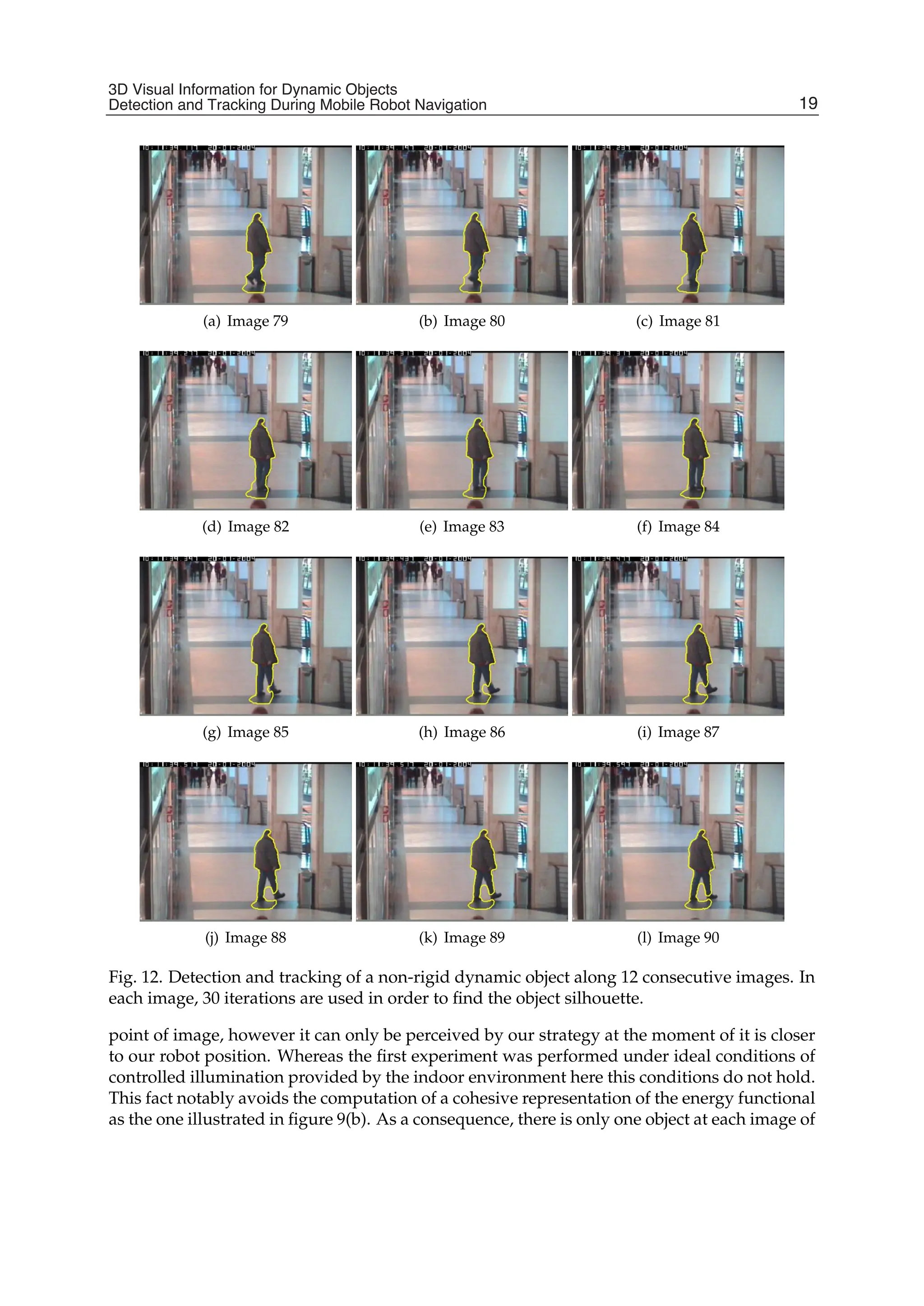
Fig. 12. Detection and tracking of a non-rigid dynamic object along 12 consecutive images. In
each image, 30 iterations are used in order to find the object silhouette.
point of image, however it can only be perceived by our strategy at the moment of it is closer
to our robot position. Whereas the first experiment was performed under ideal conditions of
controlled illumination provided by the indoor environment here this conditions do not hold.
This fact notably avoids the computation of a cohesive representation of the energy functional
as the one illustrated in figure 9(b). As a consequence, there is only one object at each image of
19
3D Visual Information for Dynamic Objects
Detection and Tracking During Mobile Robot Navigation
36.
18 Will-be-set-by-IN-TECH
figure 13but its contour is represented by two separated regions that have similar energy level
inside. Furthermore, we analyze the disparity map for obtaining the statistics of disparity
values in both regions as mentioned in section 5.3
(a) (b) (c) (d)
(e) (f) (g) (h)
Fig. 13. Experimental results in an outdoor environment during robot navigation. Images
show the detection and tracking of a rigid object.
6.3 Experiments during mobile robot navigation: non rigid objects detection
In the third experiment, we considered a mobile robot moving in an outdoor environment
again but in this case the robot finds a dynamic non-rigid object during its trajectory. The
left image of figure 14 displays the frame in which the dynamic object was detected and
initialized as a irregular contour, middle image shows the disparity map and right image
the respective initial mask. In practice detecting non-rigid objects is more complicated than
the previous experiment because a person walking has different motions in his legs than his
shoulder or his head. Because of improvements, we use in this experiment 40 iterations per
image for converging the active contour. Figure 15 illustrates some resulted images of the
tracking performed by our proposed strategy. In this experiment, we found that almost all
the person could be covered with the active contour. However by examining the left column
(a) Initial detection (b) disparity map (c) Initial mask
Fig. 14. a) Initial contour derived from the dynamic group of points. b) The corresponding
disparity map of the image, c) the initial mask used by the active contour.
20 Recent Advances in Mobile Robotics
37.
3D Visual Informationfor Dynamic Objects Detection and Tracking During Mobile Robot Navigation 19
(a) (b) (c)
(d) (e) (f)
(g) (h) (i)
(j) (k) (l)
(m) (n) (o)
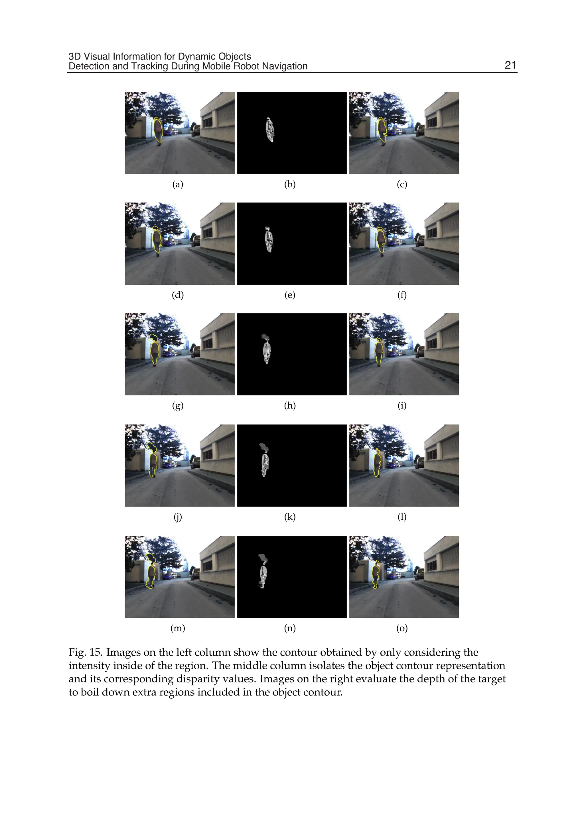
Fig. 15. Images on the left column show the contour obtained by only considering the
intensity inside of the region. The middle column isolates the object contour representation
and its corresponding disparity values. Images on the right evaluate the depth of the target
to boil down extra regions included in the object contour.
21
3D Visual Information for Dynamic Objects
Detection and Tracking During Mobile Robot Navigation
38.
20 Will-be-set-by-IN-TECH
of figure15, we can figure out that part of the background was also included in our object
region. To overcome this problem we performed the same statistical calculation of disparity
values inside of the region-object as described in section 5.3. By examining the middle column
of figure 15, we can figure out that similar depth values are concentrated in actual object
contour. We can see that additional zones to this contour that represents the tree and other
locations of the background will be rejected using the disparity map since they provide lower
values of disparity, that is they are farther away than our interesting moving object.
The proposed algorithm was coded on C/C++ and TCL, however disparity maps are
computed for the FPGA by means of an architecture codified in VHDL. The Cyclone IV card
calculates 30 disparity maps per second. After several tests, we measure that our algorithm
runs around 1 or 1.5 Hz depending of the nature of the environment. From this, note that
the disparity is available at higher frequency than our algorithm performance, however we
comment that until now the goal of the experiment was to provide an algorithm for detecting
and tracking moving objects.
7. Conclusions
In this project, we considered the problem of dynamic object detection from a mobile robot
in indoor/outdoor environments of navigation. Specially, the proposed strategy uses only
visual-information provided by a stereo-vision bank mounted on the mobile robot. The speed
of the robot during navigation is established low to avoid disturbance on the velocity data
due to robot ego-motion. Experimental results allow us to realize that the proposed strategy
performs a correct and total detection of the rigid and non-rigid objects and it is able to
tracking them along the image sequence. Motivated by these results future contributions
to this project consist in decreasing the time of computation. Nevertheless, we make some
assumptions by avoiding excessive or unnecessary computations ie. the number of selected
feature points, number of iterations during the active contour processing, our global algorithm
is not able to perform in real time (at least 10 Hz). Significant improvements could be obtained
by an emigration of all our algorithm design to embedded architectures like GPU or FPGA
devices. Furthermore these kinds of devices provide a high portability towards robotics or
autonomous vehicle platforms.
We also comment the difficulties rising from the disparity map constructed by the stereo
vision module in which a cohesive and accurate representation of the actual scene have to be
improved. To this end, future works consider the addition of a strategy for rejecting spikes
in the disparity map cased by stereo mismatches.
8. Acknowledgments
This work was partially funded by the CONACyT with the project entitled “Diseno y
optimizacion de una arquitectura para la clasificacion de objetos en tiempo real por color y
textura basada en FPGA”. Authors would like to thank Cyril Roussillon for help provided
with the robot.
9. References
Almanza-Ojeda, D., Devy, M. Herbulot, A. (2010). Visual-based detection and tracking
of dynamic obstacles from a mobile robot, In Proceedings of the 7th International
Conference on Informatics in Control, Automation and Robotics (ICINCO 2010), Madeira,
Portugal.
22 Recent Advances in Mobile Robotics
39.
3D Visual Informationfor Dynamic Objects Detection and Tracking During Mobile Robot Navigation 21
Almanza-Ojeda, D. L., Devy, M. Herbulot, A. (2011). Active method for mobile object
detection from an embedded camera, based on a contrario clustering, in J. A. Cetto,
J.-L. Ferrier J. Filipe (eds), Informatics in Control, Automation and Robotics, Vol. 89
of Lecture Notes in Electrical Engineering, Springer Berlin Heidelberg, pp. 267–280.
10.1007/978-3-642-19539-6_18.
URL: http://dx.doi.org/10.1007/978-3-642-19539-6_18
Brox, T., Rousson, M., Deriche, R. Weickert, J. (2010). Colour, texture, and motion in level
set based segmentation and tracking, Image Vision Comput. 28(3): 376–390.
Cao, F., Delon, J., Desolneux, A., Musé, P. Sur, F. (2007). A unified framework for detecting
groups and application to shape recognition, Journal of Mathematical Imaging and
Vision 27(2): 91–119.
Chan, T. Vese, L. (2001). Active contours without edges, Transactions on Image Processing,
IEEE 10(2): 266–277.
Desolneux, A., Moisan, L. Morel, J.-M. (2003). A grouping principle and four applications,
IEEE Transactions on Pattern Analysis and Machine Intelligence 25(4): 508–513.
Desolneux, A., Moisan, L. Morel, J.-M. (2008). From Gestalt Theory to Image Analysis A
Probabilistic Approach, Vol. 34, Springer Berlin / Heidelberg.
Fisher, R. (2011).
URL: http://groups.inf.ed.ac.uk/vision/CAVIAR/CAVIARDATA1/
Ibarra-Manzano, M.-A. Almanza-Ojeda, D.-L. (2011). Advances in Stereo Vision, InTech,
chapter High-Speed Architecture Based on FPGA for a Stereo-Vision Algorithm,
pp. 71-88.
Ibarra-Manzano, M., Almanza-Ojeda, D.-L., Devy, M., Boizard, J.-L. Fourniols, J.-Y. (2009).
Stereo vision algorithm implementation in fpga using census transform for effective
resource optimization, Digital System Design, Architectures, Methods and Tools, 2009.
12th Euromicro Conference on, pp. 799 –805.
Ibarra-Manzano, M., Devy, M., Boizard, J.-L., Lacroix, P. Fourniols, J.-Y. (2009). An
efficient reconfigurable architecture to implement dense stereo vision algorithm
using high-level synthesis, 2009 International Conference on Field Programmable Logic
and Applications, Prague, Czech Republic, pp. 444–447.
Katz, R., Douillard, B., Nieto, J. Nebot, E. (2008). A self-supervised architecture for
moving obstacles classification, IEEE/RSJ International Conference on Intelligent Robots
and Systems, IROS 2008, pp. 155–160.
Klappstein, J., Vaudrey, T., Rabe, C., Wedel, A. Klette, R. (2008). Moving object segmentation
using optical flow and depth information, PSIVT ’09: Proceedings of the 3rd Pacific
Rim Symposium on Advances in Image and Video Technology, Springer-Verlag, Berlin,
Heidelberg, pp. 611–623.
Li, C., Xu, C., Gui, C. Fox, M. D. (2010). Distance regularized level set evolution and its
application to image segmentation, IEEE Trans. Image Process. 19(12): 3243–3254.
Lookingbill, A., Lieb, D. Thrun, S. (2007). Autonomous Navigation in Dynamic Environments,
Vol. 35 of Springer Tracts in Advanced Robotics, Springer Berlin / Heidelberg, pp. 29–44.
Lucas, B. D. Kanade, T. (1981). An iterative image registration technique with an application
to stereo vision, Proceedings of DARPA Image Understanding Workshop, pp. 121–130.
Marin-Hernandez, A. (2004). Vision dynamique pour la navigation d’un robot mobile., PhD thesis,
INPT-LAAS-CNRS.
Masrani, D. MacLean, W. (2006). A Real-Time large disparity range Stereo-System using
FPGAs, Computer Vision Systems, 2006 ICVS ’06. IEEE International Conference on, p. 13.
23
3D Visual Information for Dynamic Objects
Detection and Tracking During Mobile Robot Navigation
40.
22 Will-be-set-by-IN-TECH
Matthies, L.,Litwin, T., Owens, K., Rankin, A., Murphy, K., Coombs, D., Gilsinn, J., Hong,
T., Legowik, S., Nashman, M. Yoshimi, B. (1998). Performance evaluation of
ugv obstacle detection with ccd/flir stereo vision and ladar, ISIC/CIRA/ISAS Joint
Conference pp. 658–670.
Paragios, N. Deriche, R. (2005). Geodesic active regions and level set methods for motion
estimation and tracking, Computer Vision and Image Understanding 97(3): 259 – 282.
URL: http://www.sciencedirect.com/science/article/pii/S1077314204001213
Schmit, H. H., Cadambi, S., Moe, M. Goldstein, S. C. (2000). Pipeline reconfigurable fpgas,
Journal of VLSI Signal Processing Systems 24(2-3): 129–146.
Sekhar, S. C., Aguet, F., Romain, S., Thévenaz, P. Unser, M. (2008). Parametric
b-spline snakes on distance maps—application to segmentation of histology images,
Proceedings of the 16th European Signal Processing Conference, (EUSIPCO2008) .
Shi, J. Tomasi, C. (1994). Good features to track, proceedings of the IEEE Conference on Computer
Vision and Pattern Recognition, pp. 593–600.
Sola, J., Monin, A. Devy, M. (2007). BiCamSLAM: two times mono is more than stereo, IEEE
International Conference on Robotics Automation (ICRA2007), Rome, Italy, pp. 4795–4800.
Talukder, A. Matthies, L. (2004). Real-time detection of moving objects from moving
vehicles using dense stereo and optical flow, proceedings of the International Conference
on Intelligent Robots and Systems (IROS2004), pp. 3718–3725.
Veit, T., Cao, F. Bouthemy, P. (2007). Space-time a contrario clustering for detecting coherent
motion, IEEE International Conference on Robotics and Automation, (ICRA07), Roma,
Italy, pp. 33–39.
Vu, T. Aycard, O. (2009). Laser-based detection and tracking moving objects using
data-driven markov chain monte carlo, IEEE International Conference on Robotics
Automation (ICRA2009), Kobe, Japan.
Williamson, T. (1998). A High-Performance Stereo Vision System for Obstacle Detection, PhD thesis,
Robotics Institute, Carnegie Mellon University, Pittsburgh, PA.
Woodfill, J., Gordon, G., Jurasek, D., Brown, T. Buck, R. (2006). The tyzx DeepSea g2 vision
system, ATaskable, embedded stereo camera, Computer Vision and Pattern Recognition
Workshop, 2006. CVPRW ’06. Conference on, p. 126.
Zabih, R. Woodfill, J. (1994). Non-parametric local transforms for computing visual
correspondence, ECCV ’94: Proceedings of the Third European Conference on Computer
Vision, Vol. II, Springer-Verlag New York, Inc., Secaucus, NJ, USA, pp. 151–158.
24 Recent Advances in Mobile Robotics
41.
1. Introduction
Unlike thetraditional robotic systems in which the perceptual behaviors are manually
designed by programmers for a given task and environment, autonomous perception of
the world is one of the challenging issues in the cognitive robotics. It is known that the
selective attention mechanism serves to link the processes of perception, action and learning
(Grossberg, 2007; Tipper et al., 1998). It endows humans with the cognitive capability that allows
them to learn and think about how to perceive the environment autonomously. This visual
attention based autonomous perception mechanism involves two aspects: conscious aspect
that directs perception based on the current task and learned knowledge, and unconscious
aspect that directs perception in the case of facing an unexpected or unusual situation. The
top-down attention mechanism (Wolfe, 1994) is responsible for the conscious aspect whereas
the bottom-up attention mechanism (Treisman Gelade, 1980) corresponds to the unconscious
aspect. This paper therefore discusses about how to build an artificial system of autonomous
visual perception.
Three fundamental problems are addressed in this paper. The first problem is about
pre-attentive segmentation for object-based attention. It is known that attentional selection
is either space-based or object-based (Scholl, 2001). The space-based theory holds that attention
is allocated to a spatial location (Posner et al., 1980). The object-based theory, however, posits
that some pre-attentive processes serve to segment the field into discrete objects, followed
by the attention that deals with one object at a time (Duncan, 1984). This paper proposes
that object-based attention has the following three advantages in terms of computations:
1) Object-based attention is more robust than space-based attention since the attentional
activation at the object level is estimated by accumulating contributions of all components
within that object, 2) attending to an exact object can provide more useful information (e.g.,
shape and size) to produce the appropriate actions than attending to a spatial location, and
3) the discrete objects obtained by pre-attentive segmentation are required in the case that a
global feature (e.g., shape) is selected to guide the top-down attention. Thus this paper adopts
the object-based visual attention theory (Duncan, 1984; Scholl, 2001).
Although a few object-based visual attention models have been proposed, such as (Sun, 2008;
Sun Fisher, 2003), developing a pre-attentive segmentation algorithm is still a challenging
issue as it is a unsupervised process. This issue includes three types of challenges: 1) The
Development of an Autonomous Visual
Perception System for Robots Using
Object-Based Visual Attention
Yuanlong Yu, George K. I. Mann and Raymond G. Gosine
Faculty of Engineering and Applied Science, Memorial University of Newfoundland
St. John’s, NL,
Canada
2
42.
2 Will-be-set-by-IN-TECH
ability toautomatically determine the number of segments (termed as self-determination), 2)
the computational efficiency, and 3) the robustness to noise. Although K-labeling methods
(e.g., normalized cut (Shi Malik, 2000)) can provide the accuracy and robustness, they are
ineffective and inefficient when the number of segments is unknown. In contrast, recent
split-and-merge methods (e.g., irregular pyramid based segmentation (Sharon et al., 2006))
are capable of determining the number of segments and computationally efficient, whereas
they are not robust to noise. This paper proposes a new pre-attentive segmentation algorithm
based on the irregular pyramid technique in order to achieve the self-determination and
robustness as well as keep the balance between the accuracy and efficiency.
The second problem is about how to model the attentional selection, i.e., model the cognitive
capability of thinking about what should be perceived. Compared with the well-developed
bottom-up attention models (Itti Baldi, 2009; Itti et al., 1998), modeling the top-down
attention is far from being well-studied. The top-down attention consists of two components:
1) Deduction of task-relevant object given the task and 2) top-down biasing that guides the
focus of attention (FOA) to the task-relevant object. Although some top-down methods have
been proposed, such as (Navalpakkam Itti, 2005), several challenging issues require further
concerns. Since the first component is greatly dependent on the knowledge representation,
it will be discussed in the next paragraph. Regarding the second component, the first issue
is about the effectiveness of top-down biasing. The main factor that decays the effectiveness
is that the task-relevant object shares some features with the distracters. It indicates that the
top-down biasing method should include a mechanism to make sure that the task-relevant
object can be discriminated from distracters. The second issue is about the computational
efficiency based on the fact that the attention is a fast process to select an object of interest from
the image input. Thus it is reasonable to use some low-level features rather than high-level
features (e.g., the iconic representation (Rao Ballard, 1995a)) for top-down biasing. The
third one is the adaptivity to automatically determine which feature(s) is used for top-down
biasing such that the requirement of manually re-selecting the features for different tasks and
environment is eliminated. This paper attempts to address the above issues by using the
integrated competition (IC) hypothesis (Duncan et al., 1997) since it not only summarizes a
theory of the top-down attention, which can lead to a computational model with effectiveness,
efficiency and adaptivity, but also integrates the object-based attention theory. Furthermore,
it is known that bottom-up attention and top-down attention work together to decide the
attentional selection, but how to combine them is another challenging issue due to the
multi-modality of bottom-up saliency and top-down biases. A promising approach to this
issue is setting up a unified scale at which they can be combined.
The third problem is about the cognitive capability of autonomously learning the knowledge
that is used to guide the conscious perceptual behavior. According to the psychological
concept, the memory used to store this type of knowledge is called long-term memory (LTM).
Regarding this problem, the following four issues are addressed in this paper. The first
issue is about the unit of knowledge representations. Object-based vision theory (Duncan,
1984; Scholl, 2001) indicates that a general way of organizing the visual scene is to parcel it
into discrete objects, on which perception, action and learning perform. In other words, the
internal attentional representations are in the form of objects. Therefore objects are used as
the units of the learned knowledge. The second issue is what types of knowledge should be
modeled for guiding the conscious perceptual behavior. According to the requirements of
the attention mechanism, this paper proposes that the knowledge mainly includes LTM task
representations and LTM object representations. The LTM task representation embodies the
26 Recent Advances in Mobile Robotics
43.
Development of anAutonomous Visual Perception System for Robots Using Object-Based Visual Attention 3
association between the attended object at the last time and predicted task-relevant object
at the current time. In other words, it tells the robot what should be perceived at each
time. Thus its objective is to deduce the task-relevant object given the task in the attentional
selection stage. The LTM object representation embodies the properties of an object. It has two
objectives: 1) Directing the top-down biasing given the task-relevant object and 2) directing
the post-attentive perception and action selection. The third issue is about how to build
their structure in order to realize the objectives of these two representations. This paper
employs the connectionist approach to model both representations as the self-organization can
be more effectively achieved by using the cluster-based structure, although some symbolic
approaches (Navalpakkam Itti, 2005) have been proposed for task representations. The
last issue is about how to learn both representations through the duration from an infant
robot to a mature one. It indicates that a dynamic, constructive learning algorithm is required
to achieve the self-organization, such as generation of new patterns and re-organization of
existing patterns. Since this paper focuses on the perception process, only the learning of LTM
object representations is presented.
The remainder of this paper is organized as follows. Some related work of modeling visual
attention and its applications in robotic perception are reviewed in section 2. The framework
of the proposed autonomous visual perception system is given in section 3. Three stages of this
proposed system are presented in section 4, section 5 and section 6 respectively. Experimental
results are finally given in section 7.
2. Related work
There are mainly four psychological theories of visual attention, which are the basis of
computational modeling. Feature integration theory (FIT) (Treisman Gelade, 1980) is widely
used for explaining the space-based bottom-up attention. The FIT asserts that the visual scene
is initially coded along a variety of feature dimensions, then attention competition performs
in a location-based serial fashion by combining all features spatially, and focal attention finally
provides a way to integrate the initially separated features into a whole object. Guided
search model (GSM) (Wolfe, 1994) was further proposed to model the space-based top-down
attention mechanism in conjunction with bottom-up attention. The GSM posits that the
top-down request for a given feature will activate the locations that might contain the given
feature. Unlike FIT and GSM, the biased competition (BC) hypothesis (Desimone Duncan,
1995) asserts that attentional selection, regardless of being space-based or object-based, is a
biased competition process. Competition is biased in part by the bottom-up mechanism that
favors a local inhomogeneity in the spatial and temporal context and in part by the top-down
mechanism that favors items relative to the current task. By extending the BC hypothesis,
the IC hypothesis (Duncan, 1998; Duncan et al., 1997) was further presented to explain the
object-based attention mechanism. The IC hypothesis holds that any property of an object can
be used as a task-relevant feature to guide the top-down attention and the whole object can
be attended once the task-relevant feature successfully captures the attention.
A variety of computational models of space-based attention for computer vision have been
proposed. A space-based bottom-up attention model was first built in (Itti et al., 1998).
The surprise mechanism (Itti Baldi, 2009; Maier Steinbach, 2010) was further proposed
to model the bottom-up attention in terms of both spatial and temporal context. Itti’s
model was further extended in (Navalpakkam Itti, 2005) by modeling the top-down
attention mechanism. One contribution of Navalpakkam’s model is the symbolic knowledge
27
Development of an Autonomous Visual Perception
System for Robots Using Object-Based Visual Attention
44.
4 Will-be-set-by-IN-TECH
representations thatare used to deduce the task-relevant entities for top-down attention. The
other contribution is the multi-scale object representations that are used to bias attentional
selection. However, this top-down biasing method might be ineffective in the case that
environment contains distracters which share one or some features with the target. Another
model that selectively tunes the visual processing networks by a top-down hierarchy of
winner-take-all processes was also proposed in (Tsotsos et al., 1995). Some template matching
methods such as (Rao et al., 2002), and neural networks based methods, such as (Baluja
Pomerleau, 1997; Hoya, 2004), were also presented for modeling top-down biasing. Recently
an interesting computational method that models attention as a Bayesian inference process
was reported in (Chikkerur et al., 2010). Some space-based attention model for robots was
further proposed in (Belardinelli Pirri, 2006; Belardinelli et al., 2006; Frintrop, 2005) by
integrating both bottom-up and top-down attention.
Above computational models direct attention to a spatial location rather than a perceptual
object. An alternative, which draws attention to an object, has been proposed by (Sun Fisher,
2003). It presents a computational method for grouping-based saliency and a hierarchical
framework for attentional selection at different perceptual levels (e.g. a point, a region or
an object). Since the pre-attentive segmentation is manually achieved in the original work,
Sun’s model was further improved in (Sun, 2008) by integrating an automatic segmentation
algorithm. Some object-based visual attention models (Aziz et al., 2006; Orabona et al., 2005)
have also been presented. However, the top-down attention is not fully achieved in these
existing object-based models, e.g., how to get the task-relevant feature is not realized.
Visual attention has been applied in several robotic tasks, such as object recognition (Walther
et al., 2004), object tracking (Frintrop Kessel, 2009), simultaneous localization and mapping
(SLAM) (Frintrop Jensfelt, 2008) and exploration of unknown environment (Carbone et al.,
2008). A few general visual perception models (Backer et al., 2001; Breazeal et al., 2001) are also
presented by using visual attention. Furthermore, some research (Grossberg, 2005; 2007) has
proposed that the adaptive resonance theory (ART) (Carpenter Grossberg, 2003) can predict
the functional link between attention and processes of consciousness, learning, expectation,
resonance and synchrony.
3. Framework of the proposed system
The proposed autonomous visual perception system involves three successive stages:
pre-attentive processing, attentional selection and post-attentive perception. Fig. 1 illustrates
the framework of this proposed system.
Stage 1: The pre-attentive processing stage includes two successive steps. The first step is the
extraction of pre-attentive features at multiple scales (e.g., nine scales for a 640 × 480 image).
The second step is the pre-attentive segmentation that divides the scene into proto-objects in
an unsupervised manner. The proto-objects can be defined as uniform regions such that the
pixels in the same region are similar. The obtained proto-objects are the fundamental units of
attentional selection.
Stage 2: The attentional selection stage involves four modules: bottom-up attention, top-down
attention, a combination of bottom-up saliency and top-down biases, as well as estimation
of proto-object based attentional activation. The bottom-up attention module aims to model
the unconscious aspect of the autonomous perception. This module generates a probabilistic
location-based bottom-up saliency map. This map shows the conspicuousness of a location
compared with others in terms of pre-attentive features. The top-down attention module aims
28 Recent Advances in Mobile Robotics
45.
Development of anAutonomous Visual Perception System for Robots Using Object-Based Visual Attention 5
Fig. 1. The framework of the proposed autonomous visual perception system for robots.
to model the conscious aspect of the autonomous perception. This module is modeled based
on the IC hypothesis and consists of four steps. Step 1 is the deduction of the task-relevant
object from the corresponding LTM task representation given the task. Step 2 is the deduction
of the task-relevant feature dimension(s) from the corresponding LTM object representation
given the task-relevant object. Step 3 is to build the attentional template(s) in working memory
(WM) by recalling the task-relevant feature(s) from LTM. Step 4 is to estimate a probabilistic
location-based top-down bias map by comparing attentional template(s) with corresponding
pre-attentive feature(s). The obtained top-down biases and bottom-up saliency are combined
in a probabilistic manner to yield a location-based attentional activation map. By combining
location-based attentional activation within each proto-object, a proto-object based attentional
activation map is finally achieved, based on which the most active proto-object is selected for
attention.
Stage 3: The main objective of the post-attentive perception stage is to interpret the attended
object in more detail. The detailed interpretation aims to produce the appropriate action and
learn the corresponding LTM object representation at the current time as well as to guide
the top-down attention at the next time. This paper introduces four modules in this stage.
The first module is perceptual completion processing. Since an object is always composed of
several parts, this module is required to perceive the complete region of the attended object
post-attentively. In the following text, the term attended object is used to represent one or all of
the proto-objects in the complete region being attended. The second module is the extraction
of post-attentive features that are a type of representation of the attended object in WM and
used for the following two modules. The third module is object recognition. It functions as
a decision unit that determines to which LTM object representation and/or to which instance
of that representation the attended object belongs. The fourth module is learning of LTM
29
Development of an Autonomous Visual Perception
System for Robots Using Object-Based Visual Attention
46.
6 Will-be-set-by-IN-TECH
object representations.This module aims to develop the corresponding LTM representation
of the attended object. The probabilistic neural network (PNN) is used to build the LTM
object representation. Meanwhile, a constructive learning algorithm is also proposed. Note
that the LTM task representation is another important module in the post-attentive perception
stage. Its learning requires the perception-action training pairs, but this paper focuses on the
perception process rather than the action selection process. So this module will be discussed
in the future work.
4. Pre-attentive processing
4.1 Extraction of pre-attentive features
(a) (b) (c) (d)
(e) (f) (g) (h)
Fig. 2. Pre-attentive features at the original scale. (a) Intensity. (b) Red-green. (c) Blue-yellow.
(d) Contour. (e) - (h) Orientation energy in direction 0◦, 45◦, 90◦ and 135◦ respectively.
Brightness represents the energy value.
By using the method in Itti’s model (Itti et al., 1998), pre-attentive features are extracted at
multiple scales in the following dimensions: intensity Fint, red-green Frg, blue-yellow Fby,
orientation energy Foθ with θ ∈ {0◦, 45◦, 90◦, 135◦}, and contour Fct. Symbol F is used to
denote pre-attentive features.
Given 8-bit RGB color components r, g and b of the input image, intensity and color pairs
at the original scale are extracted as : Fint = (r + g + b)/3, Frg = R − G, Fby = B − Y,
where R = r − (g + b)/2, G = g − (r + b)/2, B = b − (r + g)/2, and Y = (r + g)/2 −
|r − g|/2 − b. Gaussian pyramid (Burt Adelson, 1983) is used to create the multi-scale
intensity and color pairs. The multi-scale orientation energy is extracted using the Gabor
pyramid (Greenspan et al., 1994). The contour feature Fct(s) is approximately estimated
by applying a pixel-wise maximum operator over four orientations of orientation energy:
Fct(s) = maxθ∈{0◦,45◦,90◦,135◦} Foθ (s), where s denotes the spatial scale. Examples of the
extracted pre-attentive features have been shown in Fig. 2.
4.2 Pre-attentive segmentation
This paper proposes a pre-attentive segmentation algorithm by extending the irregular
pyramid techniques (Montanvert et al., 1991; Sharon et al., 2000; 2006). As shown in Fig. 3,
30 Recent Advances in Mobile Robotics
47.
Development of anAutonomous Visual Perception System for Robots Using Object-Based Visual Attention 7
the pre-attentive segmentation is modeled as a hierarchical accumulation procedure, in which
each level of the irregular pyramid is built by accumulating similar local nodes at the level
below. The final proto-objects emerge during this hierarchical accumulation process as they
are represented by single nodes at some levels. This accumulation process consists of four
procedures.
Fig. 3. An illustration of the hierarchical accumulation process in the pre-attentive segmentation. This
process is shown from bottom to top. In the left figure, this process is represented by vertices and each
circle represents a vertex. In the right figure, this process is represented by image pixels and each block
represents an image pixel. The color of each vertex and block represents the feature value. It can be seen
that the image is partitioned into three irregular regions once the accumulation process is finished.
Procedure 1 is decimation. A set of surviving nodes (i.e., parent nodes) is selected from the
son level to build the parent level. This procedure is constrained by the following two rules
(Meer, 1989): 1) Any two neighbor son nodes cannot both survive to the parent level and
2) any son node must have at least one parent node. Instead of the random values used in the
stochastic pyramid decimation (SPD) algorithm (Jolion, 2003; Meer, 1989), this paper proposes
a new recursive similarity-driven algorithm (i.e., the first extension), in which a son node
will survive if it has the maximum similarity among its neighbors with the constraints of the
aforementioned rules. The advantage is the improved segmentation performance since the
nodes that can greatly represent their neighbors deterministically survive. As the second
extension, Bhattacharyya distance (Bhattacharyya, 1943) is used to estimate the similarity
between nodes at the same level (i.e., the strength of intra-level edges). One advantage is that
the similarity measure is approximately scale-invariant during the accumulation process since
Bhattacharyya distance takes into account the correlations of the data. The other advantage is
that the probabilistic measure can improve the robustness to noise.
In procedure 2, the strength of inter-level edges is estimated. Each son node and its parent
nodes are linked by inter-level edges. The strength of these edges is estimated in proportion
to the corresponding intra-level strength at the son level by using the method in (Sharon et al.,
2000).
Procedure 3 aims to estimate the aggregate features and covariances of each parent node based
on the strength of inter-level edges by using the method in (Sharon et al., 2000).
The purpose of procedure 4 is to search for neighbors of each parent node and simultaneously
estimate the strength of intra-level edges at the parent level. As the third extension, a new
31
Development of an Autonomous Visual Perception
System for Robots Using Object-Based Visual Attention
48.
8 Will-be-set-by-IN-TECH
(a) (b)(c) (d)
(e) (f) (g) (h)
Fig. 4. Results of pre-attentive segmentation. (a)-(d) Original images, where (d) includes salt
and pepper noise (noise density:0.1, patch size: 5 × 5 pixels). (e)-(h) Segmentation results.
Each color represents one proto-object in these results.
neighbor search method is proposed by considering not only the graphic constraints but also
the similarity constraints. A candidate node is selected as a neighbor of a center node if
the similarity between them is above a predefined threshold. Since the similarity measure
is scale-invariant, a fixed value of the threshold can be used for most pyramidal levels. The
advantage of this method is the improved segmentation performance since the connections
between nodes that are located at places with great transition are deterministically cut.
In the case that no neighbors are found for a node, it is labeled as a new proto-object. The
construction of the full pyramid is finished once all nodes at a level have no neighbors. The
membership of each node at the base level to each proto-object is iteratively calculated from
the top pyramidal level to the base level. According to the membership, each node at the base
level is finally labeled. The results of the pre-attentive segmentation are shown in Fig. 4.
5. Attentional selection
5.1 Bottom-up attention
The proposed bottom-up attention module is developed by extending Itti’s model (Itti et al.,
1998). Center-surround differences in terms of pre-attentive features are first calculated to
simulate the competition in the spatial context:
F
f (sc, ss) = |Ff (sc) Ff (ss)| (1)
where denotes across-scale subtraction, consisting of interpolation of each feature at
the surround scale to the center scale and point-by-point difference, sc = {2, 3, 4} and
ss = sc + δ with δ = {3, 4} represent the center scales and surround scales respectively,
f ∈ {int, rg, by, oθ, ct} with θ ∈ {0◦, 45◦, 90◦, 135◦}, and F
f (sc, ss) denotes a center-surround
difference map.
These center-surround differences in terms of the same feature dimension are then normalized
and combined at scale 2, termed as working scale and denoted as swk, using across-scale
32 Recent Advances in Mobile Robotics
49.
Development of anAutonomous Visual Perception System for Robots Using Object-Based Visual Attention 9
addition to yield a location-based conspicuity map of that feature dimension:
Fs
f = N
1
6
4
sc=2
sc+4
ss=sc+3
N
F
f (sc, ss)
(2)
where N is the normalization operator,
is across-scale addition, consisting of interpolation
of each normalized center-surround difference to the working scale and point-by-point
addition, f ∈ {int, rg, by, oθ, ct}, and Fs
f denotes a location-based conspicuity map.
All conspicuity maps are point-by-point added together to yield a location-based bottom-up
saliency map Sbu:
Sbu = N
Fs
ct + Fs
int +
1
2
(Fs
rg + Fs
by) +
1
4 ∑
θ
Fs
oθ
(3)
Given the following two assumptions: 1) the selection process guided by the space-based
bottom-up attention is a random event, and 2) the sample space of this random event is
composed of all spatial locations in the image, the salience of a spatial location can be used
to represent the degree of belief that bottom-up attention selects that location. Therefore, the
probability of a spatial location ri being attended by the bottom-up attention mechanism can
be estimated as:
pbu(ri) =
Sbu(ri)
∑ri
Sbu(ri )
, (4)
where pbu(ri) denotes the probability of a spatial location ri being attended by the bottom-up
attention, and the denominator ∑ri
Sbu(ri ) is the normalizing constant.
5.2 Top-down attention
5.2.1 LTM task representations and task-relevant objects
The task-relevant object can be defined as an object whose occurrence is expected by the task.
Consistent with the autonomous mental development (AMD) paradigm (Weng et al., 2001),
this paper proposes that actions include external actions that operate effectors and internal
actions that predict the next possible attentional state (i.e., attentional prediction). Since the
proposed perception system is object-based, the attentional prediction can be seen as the
task-relevant object. Thus this paper models the LTM task representation as the association
between attentional states and attentional prediction and uses it to deduce the task-relevant
object.
It can be further proposed that the LTM task representation can be modeled by using a
first-order discrete Markov process (FDMP). The FDMP can be expressed as p(at+1|at), where
at denotes the attentional state at time t and at+1 denotes the attentional prediction for time
t + 1. This definition means that the probability of each attentional prediction for the next time
can be estimated given the attentional state at the current time. The discrete attentional states
is composed of LTM object representations.
5.2.2 Task-relevant feature
According to the IC hypothesis, it is required to deduce the task-relevant feature from
the task-relevant object. This paper defines the task-relevant feature as a property that can
discriminate the object from others. Although several autonomous factors (e.g., rewards
obtained from learning) could be used, this paper uses the conspicuity quantity since it
33
Development of an Autonomous Visual Perception
System for Robots Using Object-Based Visual Attention
50.
10 Will-be-set-by-IN-TECH
is oneof the important intrinsic and innate properties of an object for measuring the
discriminability. Through a training process that statistically encapsulates the conspicuity
quantities obtained under different viewing conditions, a salience descriptor is achieved in the
LTM object representation (See details in section 6.2 and section 6.3).
Therefore the salience descriptor is used to deduce the task-relevant feature by finding the
feature dimension that has the greatest conspicuity. This deduction can be expressed as:
(frel, jrel) = arg max
f ∈{ct,int,rg,by,oθ }
max
j∈{1,2,...,Nj}
μ
s,j
f
1 + σ
s,j
f
, (5)
where Nj denotes the number of parts when f ∈ {int, rg, by, oθ} and Nj = 1 when f = ct,
μ
s,j
f and σ
s,j
f respectively denote the mean and STD of salience descriptors in terms of a feature
f in the LTM representation of the task-relevant object, frel denotes the task-relevant feature
dimension, and jrel denotes the index of the task-relevant part. The LTM object representation
can be seen in section 6.3.
In the proposed system, the most task-relevant feature is first selected for guiding top-down
attention. If the post-attentive recognition shows that the attended object is not the target, then
the next task-relevant feature is joined. This process does not stop until the attended object is
verified or all features are used.
5.2.3 Attentional template
Given the task-relevant feature dimension, its appearance descriptor in the LTM representation
of the task-relevant object is used to build an attentional template in WM so as to estimate
top-down biases. The attentional template is denoted as Ft
f , where f ∈ {ct, int, rg, by, oθ}. The
appearance descriptor will be presented in section 6.3.
5.2.4 Estimation of top-down biases
Bayesian inference is used to estimate the location-based top-down bias, which represents the
probability of a spatial location being an instance of the task-relevant object. It can be generally
expressed as:
ptd(ri|Ft
f ) =
ptd(Ft
f |ri) × ptd(ri)
∑ri
ptd(Ft
f |ri ) × ptd(ri )
, (6)
where ptd(ri) denotes the prior probability of a location ri being attended by the top-down
attention, ptd(Ft
f |ri) denotes the observation likelihood, ptd(ri|Ft
f ) is the posterior probability
of the location ri being attended by the top-down attention given the attentional template Ft
f .
Assuming that the prior probability ptd(ri) is a uniform distribution, Eq. (6) can be simplified
into estimating the observation likelihood ptd(Ft
f |ri). The detailed estimation of ptd(Ft
f |ri) for
each feature dimension, including contour, intensity, red-green, blue-yellow and orientations
can be seen in our previous object-based visual attention (OVA) model (Yu et al., 2010).
5.2.5 Discussion
Compared with existing top-down attention methods, e.g., (Navalpakkam Itti, 2005; Rao
Ballard, 1995a), the proposed method has four advantages. The first advantage is effectiveness
due to the use of both salience and appearance descriptors. These two descriptors reciprocally
34 Recent Advances in Mobile Robotics
51.
Development of anAutonomous Visual Perception System for Robots Using Object-Based Visual Attention 11
aid each other: The salience descriptor guarantees that the task-relevant object can be
effectively discriminated from distracters in terms of appearance, while the appearance
descriptor can deal with the case that the task-relevant object and distracters have similar
task-relevance values but different appearance values. The second advantage is efficiency.
The computational complexity of (Rao Ballard, 1995a) and our method can be approximated
as O(dh) and O(d
f ew
f dl) respectively, where dh denotes the dimension number of a high-level
object representation, e.g., iconic representation (Rao Ballard, 1995b) used in (Rao Ballard,
1995a), dl denotes the dimension number of a pre-attentive feature and d
f ew
f denotes the
number of one or a few pre-attentive features used in our method. Since dh d
f ew
f dl,
the computation of our method is much cheaper. The third advantage is adaptability. As
shown in (5), the task-relevant feature(s) can be autonomously deduced from the learned LTM
representation such that the requirement of redesigning the representation of the task-relevant
object for different tasks is eliminated. The fourth advantage is robustness. As shown in (6),
the proposed method gives a bias toward the task-relevant object by using Bayes’ rule, such
that it is robust to work with noise, occlusion and a variety of viewpoints and illuminative
effects.
5.3 Combination of bottom-up saliency and top-down biases
Assuming that bottom-up attention and top-down attention are two random events that are
independent, the probability of an item being attended can be modeled as the probability of
occurrence of either of these two events on that item. Thus, the probabilistic location-based
attentional activation, denoted as pattn(ri), can be obtained by combining bottom-up saliency
and top-down biases:
⎧
⎪
⎪
⎨
⎪
⎪
⎩
pattn(ri) = pbu(ri) + ptd(ri|{Ft
f }) − pbu(ri) × ptd(ri|{Ft
f }) if wbu = 1 and wtd = 1
pattn(ri) = pbu(ri) if wbu = 1 and wtd = 0
pattn(ri) = ptd(ri|{Ft
f }) if wbu = 0 and wtd = 1
, (7)
where wbu and wtd are two logic variables used as the conscious gating for bottom-up attention
and top-down attention respectively and these two variables are set according to the task.
5.4 Proto-object based attentional activation
According to the IC hypothesis, it can be seen that a competitive advantage over an object is
produced by directing attention to a spatial location in that object. Thus the probability of a
proto-object being attended can be calculated using the logic or operator on the location-based
probabilities. Furthermore, it can be assumed that two locations being attended are mutually
exclusive according to the space-based attention theory (Posner et al., 1980). As a result, the
probability of a proto-object Rg being attended, denoted as pattn(Rg), can be calculated as:
pattn(Rg) =
1
Ng
∑
ri∈Rg
ptd(ri|Ft
f ), (8)
where Rg denotes a proto-object, Ng denotes the number of pixels in Rg. The inclusion of 1/Ng
is to eliminate the influence of the proto-object’s size. The FOA is directed to the proto-object
with maximal attentional activation.
35
Development of an Autonomous Visual Perception
System for Robots Using Object-Based Visual Attention
52.
12 Will-be-set-by-IN-TECH
6. Post-attentiveperception
The flow chart of the post-attentive perception can be illustrated in Fig. 5. Four modules, as
presented in section 3, are interactive during this stage.
6.1 Perceptual completion processing
This module works around the attended proto-object, denoted as R1
attn, to achieve the
complete object region. It consists of two steps. The first step is recognition of the attended
proto-object. This step explores LTM object representations in order to determine to which
LTM object representation the attended proto-object belongs by using the post-attentive
features. The extraction of post-attentive features and the recognition algorithm will be
presented in section 6.2 and section 6.4 respectively. The matched LTM object representation,
denoted as Oattn, is then recalled from LTM.
The second step is completion processing:
1. If the local coding of Oattn includes multiple parts, several candidate proto-objects, which
are spatially close to R1
attn, are selected from the current scene. They are termed as neighbors
and denoted as a set {Rn}.
2. The local post-attentive features are extracted in each Rn.
3. Each Rn is recognized using the local post-attentive features and the matched LTM object
representation Oattn. If it is recognized as a part of Oattn, it will be labeled as a part of the
attended object. Otherwise, it will be eliminated.
4. Continue item 2 and item 3 iteratively until all neighbors have been checked.
These labeled proto-objects constitute the complete region of the attended object, which is
denoted as a set {Rattn}.
6.2 Extraction of post-attentive features
Post-attentive features F̃ are estimated by using the statistics within the attended object. They
consist of global post-attentive features F̃gb and local post-attentive features F̃lc. Each F̃ consists of
appearance component F̃
a
and salience component F̃
s
.
6.2.1 Local post-attentive features
Each proto-object, denoted as Rm
attn, in the complete region being attended (i.e., Rm
attn ∈
{Rattn}) is the unit for estimating local post-attentive features. They can be estimated as a
set that can be expressed as: F̃lc =
F̃
a
lc(Rm
attn), F̃
s
lc(Rm
attn)
T
∀Rm
attn∈{Rattn}
.
The appearance components in an entry F̃lc, denoted as F̃
a
lc = {F̃
a
f } with f ∈ {int, rg, by, oθ},
are estimated by using the mean μ̃a,m
f of Rm
attn in terms of f, i.e., F̃
a
f (Rm
attn) = μ̃a,m
f .
The salience components, denoted as F̃
s
lc = {F̃
s
f } with f ∈ {int, rg, by, oθ}, can be estimated
using the mean of conspicuity μ̃s,m
f of a Rm
attn in terms of f, i.e., F̃s
f (Rm
attn) = μ̃s,m
f . The
conspicuity quantity Fs
f in terms of f is calculated using (2).
6.2.2 Global post-attentive features
The global post-attentive feature F̃gb is estimated after the complete region of the attended
object, i.e., {Rattn}, is obtained. Since the active contour technique (Blake Isard, 1998;
MacCormick, 2000) is used to represent a contour in this paper, the estimation of F̃gb includes
36 Recent Advances in Mobile Robotics
53.
Development of anAutonomous Visual Perception System for Robots Using Object-Based Visual Attention 13
Fig. 5. The flowchart of the post-attentive perception stage.
two steps. The first step is to extract control points, denoted as a set {rcp}, of the attended
object’s contour by using the method in our previous work (Yu et al., 2010). That is, each
control point is an entry in the set {F̃gb}. The second step is to estimate the appearance and
salience components at these control points, i.e., F̃gb =
F̃
a
gb(rcp), F̃
s
gb(rcp)
T
∀rcp
. The
appearance component of an entry consists of spatial coordinates in the reference frame at
a control point, i.e., F̃
a
gb(rcp) =
xrcp yrcp
T
. The salience component of an entry is built by
using the conspicuity value Fs
ct(rcp) in terms of pre-attentive contour feature at a control point,
i.e., F̃
s
gb(rcp) = Fs
ct(rcp).
6.3 Development of LTM object representations
The LTM object representation also consists of the local coding (denoted as Olc) and global
coding (denoted as Ogb). Each coding also consists of appearance descriptors (denoted as Oa
)
and salience descriptors (denoted as Os
). The PNN (Specht, 1990) is used to build them.
6.3.1 PNN of local coding
The PNN of a local coding Olc (termed as a local PNN) includes three layers. The input layer
receives the local post-attentive feature vector F̃lc. Each radial basis function (RBF) at the
37
Development of an Autonomous Visual Perception
System for Robots Using Object-Based Visual Attention
54.
14 Will-be-set-by-IN-TECH
hidden layerrepresents a part of the learned object and thereby this layer is called a part layer.
The output layer is a probabilistic mixture of all parts belonging to the object and thereby this
layer is called an object layer.
The probability distribution of a RBF at the part layer of the local PNN can be expressed as:
pk
j (F̃lc) = G(F̃lc; μk
j , Σk
j )
=
1
(2π)
d
2 |Σk
j |
1
2
exp{−
1
2
(F̃lc − μk
j )T
(Σk
j )−1
(F̃lc − μk
j )} (9)
where G denotes the Gaussian distribution, μk
j and Σk
j denote the mean vector and covariance
matrix of a RBF, j is the index of a part, k is the index of an object in LTM, and d is the dimension
number of a local post-attentive feature F̃lc. Since all feature dimensions are assumed to
be independent, Σk
j is a diagonal matrix and standard deviation (STD) values of all feature
dimensions of a RBF can constitute an STD vector σk
j .
The probabilistic mixture estimation rk(F̃lc) at the object layer can be expressed as:
rk
(F̃lc) = ∑
i
πk
j pk
j (F̃lc), (10)
where πk
j denotes the contribution of part j to object k, which holds ∑j πk
j = 1.
6.3.2 PNN of global coding
The PNN for a global coding Ogb (termed as a global PNN) also includes three layers. The
input layer receives the global post-attentive feature vector F̃gb. Each node of the hidden layer
is a control point along the contour and thereby this layer is called a control point layer. The
output layer is a probabilistic combination of all control points belonging to the object and
thereby this layer is called an object layer. The mathematical expression of the global PNN is
similar to the local PNN.
6.3.3 Learning of LTM object representations
Since the number of nodes (i.e., the numbers of parts and control points) is unknown and
might be dynamically changed during the training course, this paper proposes a dynamical
learning algorithm by using both the maximum likelihood estimation (MLE) and a Bayes’
classifier to update the local and global PNNs at each time. This proposed dynamical learning
algorithm can be summarized as follows. The Bayes’ classifier is used to classify the training
pattern to an existing LTM pattern. If the training pattern can be classified to an existing
LTM pattern at the part level in a local PNN or at the control point level in a global PNN,
both appearance and salience descriptors of this existing LTM pattern are updated using
MLE. Otherwise, a new LTM pattern is created. Two thresholds τ1 and τ2 are introduced to
determine the minimum correct classification probability to an existing part and an existing
control point respectively. Algorithm 1 shows the learning routine of global and local codings.
In the algorithm, ak
j denotes the occurrence number of an existing pattern indexed by j of
object k and it is initialized by 0, Nk denotes the number of parts in the local PNN or control
points in the global PNN of object k, .2 denotes the element-by-element square operator, and
σinit is a predefined STD value when a new pattern is created.
38 Recent Advances in Mobile Robotics
With warmth andsplendour from her glances.
Alas! at evening, sad and unwilling,
Back must she bend her slow steps
To the dripping house, to the barren embrace
Of grisly old age.
This of course is Heinesque, and has no relation to any legend of Bertha,
but is a fair specimen of mythology in the making, and is quite in the spirit
of many of the myths that have flitted around sunset on the sea. Whatever
the explanation of their descent, the Shining One and her fleecy retinue
were transformed. When to sea or lake came Berchta (or Perchta), it was as
Bertha of the Large Foot (i.e., webbed), or of the Long Nose (beak), and her
troop were Swan-maidens. Their celestial character was changed with that
of their mistress. They became familiars of sorcerers and sorceresses. To
‘wear yellow slippers’ became the designation of a witch.
How did these fleecy white cloud-phantoms become demonised? What
connection is there between them and the enticing Lorelei and the
dangerous Rhine-daughters watching over golden treasures, once, perhaps,
metaphors of moonlight ripples? They who have listened to the wild
laughter of these in Wagner’s opera, Das Rheingold, and their weird
‘Heiayaheia!’ can hardly fail to suspect that they became associated with
the real human nymphs whom the summer sun still finds freely sporting in
the bright streams of Russia, Hungary, Austria, and East Germany, naked
and not ashamed. Many a warning voice against these careless Phrynes,
who may have left tattered raiment on the shore to be transfigured in the
silvery waves, must have gone forth from priests and anxious mothers. Nor
would there be wanting traditions enough to impress such warnings. Few
regions have been without such stories as those which the traveller Hiouen-
Thsang (7th century) found in Buddhist chronicles of the Rakshasis of
Ceylon. ‘They waylay the merchants who land in the isle, and, changing
themselves to women of great beauty, come before them with fragrant
flowers and music; attracting them with kind words to the town of Iron,
they offer them a feast, and give themselves up to pleasure with them; then
shut them in an iron prison, and eat them one after the other.’
57.
There is astrong accent of human nature in the usual plot of the Swan-
maiden legend, her garments stolen while she bathes, and her willingness to
pay wondrous prices for them—since they are her feathers and her
swanhood, without which she must remain for ever captive of the thief. The
stories are told in regions so widely sundered, and their minor details are so
different, that we may at any rate be certain that they are not all traceable
solely to fleecy clouds. Sometimes the garments of the demoness—and
these beings are always feminine—are not feathery, as in the German
stories, but seal-skins, or of nondescript red tissue. Thus, the Envoy Li
Ting-yuan (1801) records a Chinese legend of a man named Ming-ling-tzu,
a poor and worthy farmer without family, who, on going to draw water from
a spring near his house, saw a woman bathing in it. She had hung her
clothes on a pine tree, and, in punishment for her ‘shameless ways’ and for
her fouling the well, he carried off the dress. The clothing was unlike the
familiar Lewchewan in style, and ‘of a ruddy sunset colour.’ The woman,
having finished her bath, cried out in great anger, ‘What thief has been here
in broad day? Bring back my clothes, quick.’ She then perceived Ming-ling-
tzu, and threw herself on the ground before him. He began to scold her, and
asked why she came and fouled his water; to which she replied that both the
pine tree and the well were made by the Creator for the use of all. The
farmer entered into conversation with her, and pointed out that fate
evidently intended her to be his wife, as he absolutely refused to give up her
clothes, while without them she could not get away. The result was that they
were married. She lived with him for ten years, and bore him a son and a
daughter. At the end of that time her fate was fulfilled: she ascended a tree
during the absence of her husband, and having bidden his children farewell,
glided off on a cloud and disappeared.5
In South Africa a parallel myth, in its demonological aspect, bears no trace
of a cloud origin. In this case a Hottentot, travelling with a Bushwoman and
her child, met a troop of wild horses. They were all hungry; and the woman,
taking off a petticoat made of human skin, was instantly changed into a
lioness. She struck down a horse, and lapped its blood; then, at the request
of the Hottentot, who in his terror had climbed a tree, she resumed her
petticoat and womanhood, and the friends, after a meal of horseflesh,
58.
resumed their journey.6Among the Minussinian Tartars these demons
partake of the nature of the Greek Harpies; they are bloodthirsty vampyre-
demons who drink the blood of men slain in battle, darken the air in their
flight, and house themselves in one great black fiend.7 As we go East the
portrait of the Swan-maiden becomes less dark, and she is not associated
with the sea or the under-world. Such is one among the Malays, related by
Mr. Tylor. In the island of Celebes it is said that seven nymphs came down
from the sky to bathe, and were seen by Kasimbaha, who at first thought
them white doves, but in the bath perceived they were women. He stole the
robe of one of them, Utahagi, and as she could not fly without it, she
became his wife and bare him a son. She was called Utahagi because of a
single magic white hair she had; this her husband pulled out, when
immediately a storm arose, and she flew to heaven. The child was in great
grief, and the husband cast about how he should follow her up into the sky.
The Swan-maiden appears somewhat in the character of a Nemesis in a
Siberian myth told by Mr. Baring-Gould. A certain Samoyed who had stolen
a Swan-maiden’s robe, refused to return it unless she secured for him the
heart of seven demon robbers, one of whom had killed the Samoyed’s
mother. The robbers were in the habit of hanging up their hearts on pegs in
their tent. The Swan-maiden procured them. The Samoyed smashed six of
the hearts; made the seventh robber resuscitate his mother, whose soul, kept
in a purse, had only to be shaken over the old woman’s grave for that feat to
be accomplished, and the Swan-maiden got back her plumage and flew
away rejoicing.8
In Slavonic Folklore the Swan-maiden is generally of a dangerous
character, and if a swan is killed they are careful not to show it to children
for fear they will die. When they appear as ducks, geese, and other water-
fowl, they are apt to be more mischievous than when they come as pigeons;
and it is deemed perilous to kill a pigeon, as among sailors it was once held
to kill an albatross. Afanasief relates a legend which shows that, even when
associated with the water-king, the Tsar Morskoi or Slavonic Neptune, the
pigeon preserves its beneficent character. A king out hunting lies down to
drink from a lake (as in the story related on p. 146), when Tsar Morskoi
seizes him by the beard, and will not release him until he agrees to give him
59.
his infant son.The infant prince, deserted on the edge of the fatal lake, by
advice of a sorceress hides in some bushes, whence he presently sees twelve
pigeons arrive, which, having thrown off their feathers, disport themselves
in the lake. At length a thirteenth, more beautiful than the rest, arrives, and
her sorochka (shift) Ivan seizes. To recover it she agrees to be his wife, and,
having told him he will find her beneath the waters, resumes her pigeon-
shape and flies away. Beneath the lake he finds a beautiful realm, and
though the Tsar Morskoi treats him roughly and imposes heavy tasks on
him, the pigeon-maiden (Vassilissa) assists him, and they dwell together
happily.9
In Norse Mythology the vesture of the uncanny maid is oftenest a seal-skin,
and a vein of pathos enters the legends. Of the many legends of this kind,
still believed in Sweden and Norway, one has been pleasantly versified by
Miss Eliza Keary. A fisherman having found a pretty white seal-skin, took it
home with him. At night there was a wailing at his door; the maid enters,
becomes his wife, and bears him three children. But after seven years she
finds the skin, and with it ran to the shore. The eldest child tells the story to
the father on his return home.
Then we three, Daddy,
Ran after, crying, ‘Take us to the sea!
Wait for us, Mammy, we are coming too!
Here’s Alice, Willie can’t keep up with you!
Mammy, stop—just for a minute or two!’
At last we came to where the hill
Slopes straight down to the beach,
And there we stood all breathless, still
Fast clinging each to each.
We saw her sitting upon a stone,
Putting the little seal-skin on.
O Mammy! Mammy!
She never said goodbye, Daddy,
She didn’t kiss us three;
She just put the little seal-skin on
And slipt into the sea!
60.
Some of thelegends of this character are nearly as realistic as Mr.
Swinburne’s ‘Morality’ of David and Bathsheba. To imagine the scarcity of
wives in regions to which the primitive Aryan race migrated, we have only
to remember the ben trovato story of Californians holding a ball in honour
of a bonnet, in the days before women had followed them in migration. To
steal Bathsheba’s clothes, and so capture her, might at one period have been
sufficiently common in Europe to require all the terrors contained in the
armoury of tradition concerning the demonesses that might so be taken in,
and might so tempt men to take them in. In the end they might disappear,
carrying off treasures in the most prosaic fashion, or perhaps they might
bring to one’s doors a small Trojan war. It is probable that the sentiment of
modesty, so far as it is represented in the shame of nudity, was the result of
prudential agencies. Though the dread of nudity has become in some
regions a superstition in the female mind strong enough to have its martyrs
—as was seen at the sinking of the Northfleet and the burning hotel in St.
Louis—it is one that has been fostered by men in distrust of their own
animalism. In barbarous regions, where civilisation introduces clothes, the
women are generally the last to adopt them; and though Mr. Herbert
Spencer attributes this to female conservatism, it appears more probable
that it is because the men are the first to lose their innocence and the women
last to receive anything expensive. It is noticeable how generally the Swan-
maidens are said in the myths to be captured by violence or stratagem. At
the same time the most unconscious temptress might be the means of
breaking up homes and misleading workmen, and thus become invested
with all the wild legends told of the illusory phenomena of nature in popular
mythology.
It is marvellous to observe how all the insinuations of the bane were
followed by equal dexterities in the antedote. The fair tempters might
disguise their intent in an appeal to the wayfarer’s humanity; and, behold,
there were a thousand well-attested narratives ready for the lips of wife and
mother showing the demoness appealing for succour to be fatalest of all!
There is a stone on the Müggelsberger, in Altmark, which is said to cover a
treasure; this stone is sometimes called ‘Devil’s Altar,’ and sometimes it is
said a fire is seen there which disappears when approached. It lies on the
61.
verge of Teufelsee,—alake dark and small, and believed to be fathomless.
Where the stone lies a castle once stood which sank into the ground with its
fair princess. But from the underground castle there is a subterranean
avenue to a neighbouring hill, and from this hill of an evening sometimes
comes an old woman, bent over her staff. Next day there will be seen a
most beautiful lady combing her long golden hair. To all who pass she
makes her entreaties that they will set her free, her pathetic appeals being
backed by offer of a jewelled casket which she holds. The only means of
liberating her is, she announces, that some one shall bear her on his
shoulders three times round Teufelsee church without looking back. The
experiment has several times been made. One villager at his first round saw
a large hay-waggon drawn past him by four mice, and following it with his
eyes received blows on the ears. Another saw a waggon drawn by four coal-
black fire-breathing horses coming straight against him, started back, and
all disappeared with the cry ‘Lost again for ever!’A third tried and almost
got through. He was found senseless, and on recovering related that when
he took the princess on his shoulders she was light as a feather, but she
grew heavier and heavier as he bore her round. Snakes, toads, and all
horrible animals with fiery eyes surrounded him; dwarfs hurled blocks of
wood and stones at him; yet he did not look back, and had nearly completed
the third round, when he saw his village burst into flames; then he looked
behind—a blow felled him—and he seems to have only lived long enough
to tell this story. The youth of Köpernick are warned to steel their hearts
against any fair maid combing her hair near Teufelsee. But the folklore of
the same neighbourhood admits that it is by no means so dangerous for
dames to listen to appeals of this kind. In the Gohlitzsee, for example, a
midwife was induced to plunge in response to a call for aid; having aided a
little Merwoman in travail, she was given an apronful of dust, which
appeared odd until on shore it proved to be many thalers.
In countries where the popular imagination, instead of being scientific, is
trained to be religiously retrospective, it relapses at the slightest touch into
the infantine speculations of the human race. Not long ago, standing at a
shop-window in Ostend where a ‘Japanese Siren’ was on view, the clever
imposture interested me less than the comments of the passing and pausing
observers. The most frequent wonders seriously expressed were, whether
62.
she sang, orcombed her hair, or was under a doom, or had a soul to be
saved. Every question related to Circe, Ulysses and the Sirens, and other
conceptions of antiquity. The Japanese artists rightly concluded they could
float their Siren in any intellectual waters where Jonah in his whale could
pass, or a fish appear with its penny. Nay, even in their primitive form the
Sirens find their kith and kin still haunting all the coasts of northern Europe.
A type of the Irish and Scottish Siren may be found in the very complete
legend of one seen by John Reid, shipmaster of Cromarty. With long
flowing yellow hair she sat half on a rock, half in water, nude and beautiful,
half woman half fish, and John managed to catch and hold her tight till she
had promised to fulfil three wishes; then, released, she sprang into the sea.
The wishes were all fulfilled, and to one of them (though John would never
reveal it) the good-luck of the Reids was for a century after ascribed.10
The scene of this legend is the ‘Dropping Cave,’ and significantly near the
Lover’s Leap. One of John’s wishes included the success of his courtship.
These Caves run parallel with that of Venusberg, where the minstrel
Tannhäuser is tempted by Venus and her nymphs. Heine finishes off his
description of this Frau Venus by saying he fancied he met her one day in
the Place Bréda. ‘What do you take this lady to be?’ asked he of Balzac,
who was with him. ‘She is a mistress,’ replied Balzac. ‘A duchess rather,’
returned Heine. But the friends found on further explanation that they were
both quite right. Venus’ doves, soiled for a time, were spiritualised at last
and made white, while the snowy swan grew darker. An old German word
for swan, elbiz, originally denoting its whiteness (albus), furthered its
connection with all ‘elfish’ beings—elf being from the same word, meaning
white; but, as in Goethe’s ‘Erl König,’ often disguising a dark character.
The Swan and the Pigeon meet (with some modifications) as symbols of the
Good and Evil powers in the legend of Lohengrin. The witch transforms the
boy into a Swan, which, however, draws to save his sister, falsely accused
of his murder, the Knight of the Sangreal, who, when the mystery of his
holy name is inquired into by his too curious bride, is borne away by white
doves. These legends all bear in them, however faintly, the accent of the
early conflict of religion with the wild passions of mankind. Their religious
bearings bring us to inquiries which must be considered at a later phase of
our work. But apart from purely moral considerations, it is evident that
63.
there must havebeen practical dangers surrounding the early social chaos
amid which the first immigrants in Europe found themselves.
Although the legend of Lady Godiva includes elements of another origin, it
is probable that in the fate of Peeping Tom there is a distant reflection of the
punishment sometimes said to overtake those who gazed too curiously upon
the Swan-maiden without her feathers. The devotion of the nude lady of
Coventry would not be out of keeping with one class of these mermaiden
myths. There is a superstition, now particularly strong in Iceland, that all
fairies are children of Eve, whom she hid away on an occasion when the
Lord came to visit her, because they were not washed and presentable. So
he condemned them to be for ever invisible. This superstition seems to be
related to an old debate whether these præternatural beings are the children
of Adam and Eve or not. A Scotch story bears against that conclusion. A
beautiful nymph, with a slight robe of green, came from the sea and
approached a fisherman while he was reading his Bible. She asked him if it
contained any promise of mercy for her. He replied that it contained an offer
of salvation to ‘all the children of Adam;’ whereupon with a loud shriek she
dashed into the sea again. Euphemism would co-operate with natural
compassion in saying a good word for ‘the good little people,’ whether
hiding in earth or sea. In Altmark, ‘Will-o’-wisps’ are believed to be the
souls of unbaptized children—sometimes of lunatics—unable to rest in their
graves; they are called ‘Light-men,’ and it is said that though they may
sometimes mislead they often guide rightly, especially if a small coin be
thrown them,—this being also an African plan of breaking a sorcerer’s
spell. Christianity long after its advent in Germany had to contend seriously
with customs and beliefs found in some lakeside villages where the
fishermen regarded themselves as in friendly relations with the
præternatural guardians of the waters, and unto this day speak of their
presiding sea-maiden as a Holy Fräulein. They hear her bells chiming up
from the depths in holy seasons to mingle with those whose sounds are
wafted from church towers; and it seems to have required many fables, told
by prints of fishermen found sitting lifeless on their boats while listening to
them, to gradually transfer reverence to the new christian fairy.
64.
It may bethey heard some such melody as that which has found its finest
expression in Mr. Matthew Arnold’s ‘Forsaken Merman:’—
Children dear, was it yesterday
(Call yet once) that she went away?
Once she sate with you and me,
On a red gold throne in the heart of the sea,
And the youngest sate on her knee.
She comb’d its bright hair, and she tended it well,
When down swung the sound of the far-off bell.
She sigh’d, she look’d up through the clear green sea;
She said: ‘I must go, for my kinsfolk pray
In the little grey church on the shore to-day.
’Twill be Easter-time in the world—ah me!
And I lose my poor soul, Merman, here with thee.’
I said, ‘Go up, dear heart, through the waves,
Say thy prayer, and come back to the kind sea-caves.’
She smil’d, she went up through the surf in the bay.
Children dear, was it yesterday?
Perhaps we should find the antecedents of this Merman’s lost Margaret,
whom he called back in vain, in the Danish ballad of ‘The Merman and the
Marstig’s Daughter,’ who, in Goethe’s version, sought the winsome May in
church, thither riding as a gay knight on
horse of the water clear,
The saddle and bridle of sea-sand were.
They went from the church with the bridal train,
They danced in glee, and they danced full fain;
They danced them down to the salt-sea strand,
And they left them standing there, hand in hand.
65.
‘Now wait thee,love, with my steed so free,
And the bonniest bark I’ll bring for thee.’
And when they passed to the white, white sand,
The ships came sailing on to the land;
But when they were out in the midst of the sound,
Down went they all in the deep profound!
Long, long on the shore, when the winds were high,
They heard from the waters the maiden’s cry.
I rede ye, damsels, as best I can—
Tread not the dance with the Water-Man!
According to other legends, however, the realm under-sea was not a place
for weeping. Child-eyes beheld all that the Erl-king promised, in Goethe’s
ballad—
Wilt thou go, bonny boy? wilt thou go with me?
My daughters shall wait on thee daintily;
My daughters around thee in dance shall sweep,
And rock thee and kiss thee, and sing thee to sleep!
Or perhaps child-eyes, lingering in the burning glow of manhood’s passion,
might see in the peaceful sea some picture of lost love like that so sweetly
described in Heine’s ‘Sea Phantom:’—
But I still leaned o’er the side of the vessel,
Gazing with sad-dreaming glances
Down at the water, clear as a mirror,
Looking yet deeper and deeper,—
Till far in the sea’s abysses,
At first like dim wavering vapours,
Then slowly—slowly—deeper in colour,
Domes of churches and towers seemed rising,
And then, as clear as day, a city grand....
66.
Infinite longing, wondroussorrow,
Steal through my heart,—
My heart as yet scarce healed;
It seems as though its wounds, forgotten,
By loving lips again were kissed,
And once again were bleeding
Drops of burning crimson,
Which long and slowly trickle down
Upon an ancient house below there
In the deep, deep sea-town,
On an ancient, high-roofed, curious house,
Where, lone and melancholy,
Below by the window a maiden sits,
Her head on her arm reclined,—
Like a poor and uncared-for child;
And I know thee, thou poor and long-sorrowing child!
... I meanwhile, my spirit all grief,
Over the whole broad world have sought thee,
And ever have sought thee,
Thou dearly beloved,
Thou long, long lost one,
Thou finally found one,—
At last I have found thee, and now am gazing
Upon thy sweet face,
With earnest, faithful glances,
Still sweetly smiling;
And never will I again on earth leave thee.
I am coming adown to thee,
And with longing, wide-reaching embraces,
Love, I leap down to thy heart!
The temptations of fishermen to secure objects seen at the bottom of
transparent lakes, sometimes appearing like boxes or lumps of gold, and
even more reflections of objects in the upper world or air, must have been
67.
sources of danger;there are many tales of their being so beguiled to
destruction. These things were believed treasures of the little folk who live
under water, and would not part with them except on payment. In
Blumenthal lake, ‘tis said, there is an iron-bound yellow coffer which
fishermen often have tried to raise, but their cords are cut as it nears the
surface. At the bottom of the same lake valuable clothing is seen, and a
woman who once tried to secure it was so nearly drowned that it is thought
safer to leave it. The legends of sunken towns (as in Lake Paarsteinchen and
Lough Neagh), and bells (whose chimes may be heard on certain sacred
days), are probably variants of this class of delusions. They are often said to
have been sunk by some final vindictive stroke of a magician or witch
resolved to destroy the city no longer trusting them. Landslides, engulfing
seaside homes, might originate legends like that of King Gradlon’s daughter
Dahut, whom the Breton peasant sees in rough weather on rocks around
Poul-Dahut, where she unlocked the sluice-gates on the city Is in obedience
to her fiend-lover.
If it be remembered that less than fifty years ago Dr. Belon11 thought it
desirable to anatomise gold fishes, and prove in various ways that it is a
fallacy to suppose they feed on pure gold (as many a peasant near Lyons
declares of the laurets sold daily in the market), it will hardly be thought
wonderful that perilous visions of precious things were seen by early
fishermen in pellucid depths, and that these should at last be regarded as
seductive arts of Lorelei, who have given many lakes and rivers the
reputation of requiring one or more annual victims.
Possibly it was through accumulation of many dreams about beautiful
realms beneath the sea or above the clouds that suicide became among the
Norse folk so common. It was a proverb that the worst end was to die in
bed, and to die by suicide was to be like Egil, and Omund, and King Hake,
like nearly all the heroes who so passed to Valhalla. The Northman had no
doubt concerning the paradise to which he was going, and did not wish to
reach it enfeebled by age. But the time would come when the earth and
human affection must assert their claims, and the watery tribes be pictured
as cruel devourers of the living. Even so would the wood-nymphs and
mountain-nymphs be degraded, and fearful legends of those lost and
68.
1
2
3
4
5
6
7
8
9
wandering in darkforests be repeated to shuddering childhood. The actual
dangers would mask themselves in the endless disguises of illusion, the
wold and wave be peopled with cruel and treacherous seducers. Thus
suicide might gradually lose its charms, and a dismal underworld of
heartless gnomes replace the grottoes and fairies.
We may close this chapter with a Scottish legend relating to the ‘Shi’ichs,’
or Men of Peace, in which there is a strange intimation of a human mind
dreaming that it dreams, and so far on its way to waking. A woman was
carried away by these shadowy beings in order that she might suckle her
child which they had previously stolen. During her retention she once
observed the Shi’ichs anointing their eyes from a caldron, and seizing an
opportunity, she managed to anoint one of her own eyes with the ointment.
With that one eye she now saw the secret abode and all in it ‘as they really
were.’ The deceptive splendour had vanished. The gaudy ornaments of a
fairy grot had become the naked walls of a gloomy cavern. When this
woman had returned to live among human beings again, her anointed eye
saw much that others saw not; among other things she once saw a ‘man of
peace,’ invisible to others, and asked him about her child. Astonished at
being recognised, he demanded how she had been able to discover him; and
when she had confessed, he spit in her eye and extinguished it for ever.
Von Spix and Von Martin’s ‘Travels in Brazil,’ p. 243.
‘Anatomy of Melancholy.’ Fifteenth Edition, p. 124.
‘Les Dieux en Exile.’ Heinrich Heine. Revue des Deux Mondes, April, 1853.
‘Book of Songs.’ Translated by Charles E. Leland. New York: Henry Holt Co.
1874.
Dennys.
Bleek, ‘Hottentot Fables,’ p. 58.
Baring-Gould, ‘Curious Myths,’ c.
Ibid., ii. 299.
‘Shaski,’ vi. 48.
Darkness.
Shadows—Night Deities—Kobolds—Walpurgisnacht—Night asAbettor of Evil-
doers—Nightmare—Dreams—Invisible Foes—Jacob and his Phantom—Nott—
The Prince of Darkness—The Brood of Midnight—Second-Sight—Spectres of
Souter Fell—The Moonshine Vampyre—Glamour—Glam and Grettir—A Story
of Dartmoor.
From the little night which clings to man even by day—his own shadow—
to the world’s great shade of darkness, innumerable are the coverts from
which have emerged the black procession of phantoms which have haunted
the slumbers of the world, and betrayed the enterprise of man.
How strange to the first man seemed that shadow walking beside him, from
the time when he saw it as a ghost tracking its steps and giving him his
name for a ghost, on to the period in which it seemed the emanation of an
occult power, as to them who brought their sick into the streets to be healed
by the passing shadow of Peter; and still on to the day when Beaumont
wrote—
Our acts our angels are, or good or ill,
Our fatal shadows that walk by us still;
or that in which Goethe found therein the mystical symbol of the inward
arrest of our moral development, and said ‘No man can jump off of his
shadow.’And then from the culture of Europe we pass to the Feejee-
Islanders, and find them believing that every man has two spirits. One is his
shadow, which goes to Hades; the other is his image as reflected in water,
and it is supposed to stay near the place where the man dies.1 But, like the
giants of the Brocken, these demons of the Shadow are trembled at long
after they are known to be the tremblers themselves mirrored on air. Have
we not priests in England still fostering the belief that the baptized child
goes attended by a white spirit, the unbaptized by a dark one? Why then
need we apologise for the Fijians?
73.
But little needbe said here of demons of the Dark, for they are closely
related to the phantasms of Delusion, of Winter, and others already
described. Yet have they distinctive characters. As many as were the
sunbeams were the shadows; every goddess of the Dawn (Ushas) cast her
shadow; every Day was swallowed up by Night. This is the cavern where
hide the treacherous Panis (fog) in Vedic mythology, they who steal and
hide Indra’s cows; this is the realm of Hades (the invisible); this is the
cavern of the hag Thökk (dark) in Scandinavian mythology,—she who
alone of all in the universe refused to weep for Baldur when he was shut up
in Helheim, where he had been sent by the dart of his blind brother Hödr
(darkness). In the cavern of Night sleep the Seven Sleepers of Ephesus, and
Barbarossa, and all slumbering phantoms whose genius is the night-winged
raven. Thorr, the Norse Hercules, once tried to lift a cat—as it seemed to
him—from the ground; but it was the great mid-earth serpent which
encircles the whole earth. Impossible feat as it was for Thorr—who got only
one paw of the seeming cat off the ground—in that glassless and gasless
era, invention has accomplished much in that direction; but the black Cat is
still domiciled securely among idols of the mental cave.
There is an Anglo-Saxon word, cof-godas (lit. cove-gods), employed as the
equivalent of the Latin lares (the Penates, too, are interpreted as cof-godu,
cofa signifying the inner recess of a house, penetrale). The word in German
corresponding to this cofa, is koben; and from this Hildebrand conjectures
kob-old to be derived. The latter part of the word he supposes to be walt
(one who ‘presides over,’ e.g., Walter); so that the original form would be
kob-walt.2 Here, then, in the recesses of the household, among the least
enlightened of its members—the menials, who still often neutralise the
efforts of rational people to dispel the delusions of their children—the
discredited deities and demons of the past found refuge, and through a little
baptismal change of names are familiars of millions unto this day. In the
words of the ancient Hebrew, ‘they lay in their own houses prisoners of
darkness, fettered with the bonds of a long night.’ ‘No power of the fire
might give them light, neither could the bright flames of the stars lighten
that horrible night.’3 Well is it added, ‘Fear is nothing else but a betraying
of the succours which reason offereth,’ a truth which finds ample
74.
illustration in theKobolds. These imaginary beings were naturally
associated with the dark recesses of mines. There they gave the name to our
metal Cobalt. The value of Cobalt was not understood until the 17th
century, and the metal was first obtained by the Swedish chemist Brandt in
1733. The miners had believed that the silver was stolen away by Kobolds,
and these ‘worthless’ ores left in its place. Nickel had the like history, and is
named after Old Nick. So long did those Beauties slumber in the cavern of
Ignorance till Science kissed them with its sunbeam, and led them forth to
decorate the world!
How passed this (mental) cave-dweller even amid the upper splendours and
vastnesses of his unlit world? A Faust guided by his Mephistopheles only
amid interminable Hartz labyrinths.
How sadly rises, incomplete and ruddy,
The moon’s lone disk, with its belated glow,
And lights so dimly, that, as one advances,
At every step one strikes a rock or tree!
Let us then use a Jack-o’-lantern’s glances:
I see one yonder, burning merrily.
Ho, there! my friend! I’ll levy thine attendance:
Why waste so vainly thy resplendence?
Be kind enough to light us up the steep!
Tell me, if we still are standing,
Or if further we’re ascending?
All is turning, whirling, blending,
Trees and rocks with grinning faces,
Wandering lights that spin in mazes,
Still increasing and expanding.4
It could only have been at a comparatively late period of social
development that Sancho’s benediction on the inventor of sleep could have
found general response. The Red Indian found its helplessness fatal when
the ‘Nick of the Woods’ was abroad; the Scotch sailor found in it a demon’s
75.
opiate when the‘Nigg of the Sea’ was gathering his storms above the
sleeping watchman. It was among the problems of Job, the coöperation of
darkness with evil-doers.
The eye of the adulterer waiteth for the twilight;
He saith, No eye will see me,
And putteth a mask upon his face.
In the dark men break into houses;
In the day-time they shut themselves up;
They are strangers to the light.
The morning to them is the shadow of death;
They are familiar with the dark terrors of midnight.
Besides this fact that the night befriends and masks every treacherous foe, it
is also to be remembered that man is weakest at night. Not only is he
weaker than by day in the veil drawn over his senses, but physiologically
also. When the body is wearied out by the toils or combats of the day, and
the mind haunted by dreams of danger, there are present all the terrors
which Byron portrays around the restless pillow of Sardanapalus. The war-
horse of the day becomes a night-mare in the darkness. In the Heimskringla
it is recorded: ‘Vanland, Svegdir’s son, succeeded his father and ruled over
the Upsal domain. He was a great warrior, and went far around in different
lands. Once he took up his winter abode in Finland with Snio the Old, and
got his daughter Drisa in marriage; but in spring he set out leaving Drisa
behind, and although he had promised to return within three years he did
not come back for ten. Then Drisa sent a message to the witch Hulda; and
sent Visbur, her son by Vanland, to Sweden. Drisa bribed the witch-wife
Hulda, either that she should bewitch Vanland to return to Finland or kill
him. When this witch-work was going on Vanland was at Upsal, and a great
desire came over him to go to Finland, but his friends and counsellors
advised him against it, and said the witchcraft of the Fin people showed
itself in this desire of his to go there. He then became very drowsy, and laid
himself down to sleep; but when he had slept but a little while he cried out,
saying, ‘Mara was treading on him.’ His men hastened to help him; but
when they took hold of his head she trod on his legs, and when they laid
hold of his legs she pressed upon his head; and it was his death.’5
76.
This witch is,no doubt, Hildur, a Walkyr of the Edda, leading heroes to
Walhalla. Indeed, in Westphalia, nightmare is called Walriderske. It is a
curious fact that ‘Mara’ should be preserved in the French word for
nightmare, Cauche-mar, ‘cauche’ being from Latin calcare, to tread.
Through Teutonic folklore this Night-demon of many names, having floated
from England in a sieve paddled with cow-ribs, rides to the distress of an
increasingly unheroic part of the population. Nearly always still the ‘Mahrt’
is said to be a pretty woman,—sometimes, indeed, a sweetheart is
involuntarily transformed to one,—every rustic settlement abounding with
tales of how the demoness has been captured by stopping the keyhole,
calling the ridden sleeper by his baptismal name, and making the sign of the
cross; by such process the wicked beauty appears in human form, and is apt
to marry the sleeper, with usually evil results. The fondness of cats for
getting on the breasts of sleepers, or near their breath, for warmth, has made
that animal a common form of the ‘Mahrt.’ Sometimes it is a black fly with
red ring around its neck. This demoness is believed to suffer more pain than
it inflicts, and vainly endeavours to destroy herself.
In savage and nomadic times sound sleep being an element of danger, the
security which required men to sleep on their arms demanded also that they
should sleep as it were with one eye open. Thus there might have arisen
both the intense vividness which demons acquired by blending subjective
and objective impressions, and the curious inability, so frequent among
barbarians and not unknown among the men civilised, to distinguish dream
from fact. The habit of day-dreaming seems, indeed, more general than is
usually supposed. Dreams haunt all the region of our intellectual twilight,—
the borderland of mystery, where rise the sources of the occult and the
mystical which environ our lives. The daily terrors of barbarous life avail to
haunt the nerves of civilised people, now many generations after they have
passed away, with special and irrational shudders at certain objects or
noises: how then must they have haunted the dreams of humanity when,
like the daughter of Nathan the Wise, rescued from flames, it passed the
intervals of strife
With nerves unstrung through fear,
And fire and flame in all she sees or fancies;
77.
Welcome to ourwebsite – the perfect destination for book lovers and
knowledge seekers. We believe that every book holds a new world,
offering opportunities for learning, discovery, and personal growth.
That’s why we are dedicated to bringing you a diverse collection of
books, ranging from classic literature and specialized publications to
self-development guides and children's books.
More than just a book-buying platform, we strive to be a bridge
connecting you with timeless cultural and intellectual values. With an
elegant, user-friendly interface and a smart search system, you can
quickly find the books that best suit your interests. Additionally,
our special promotions and home delivery services help you save time
and fully enjoy the joy of reading.
Join us on a journey of knowledge exploration, passion nurturing, and
personal growth every day!
ebookbell.com


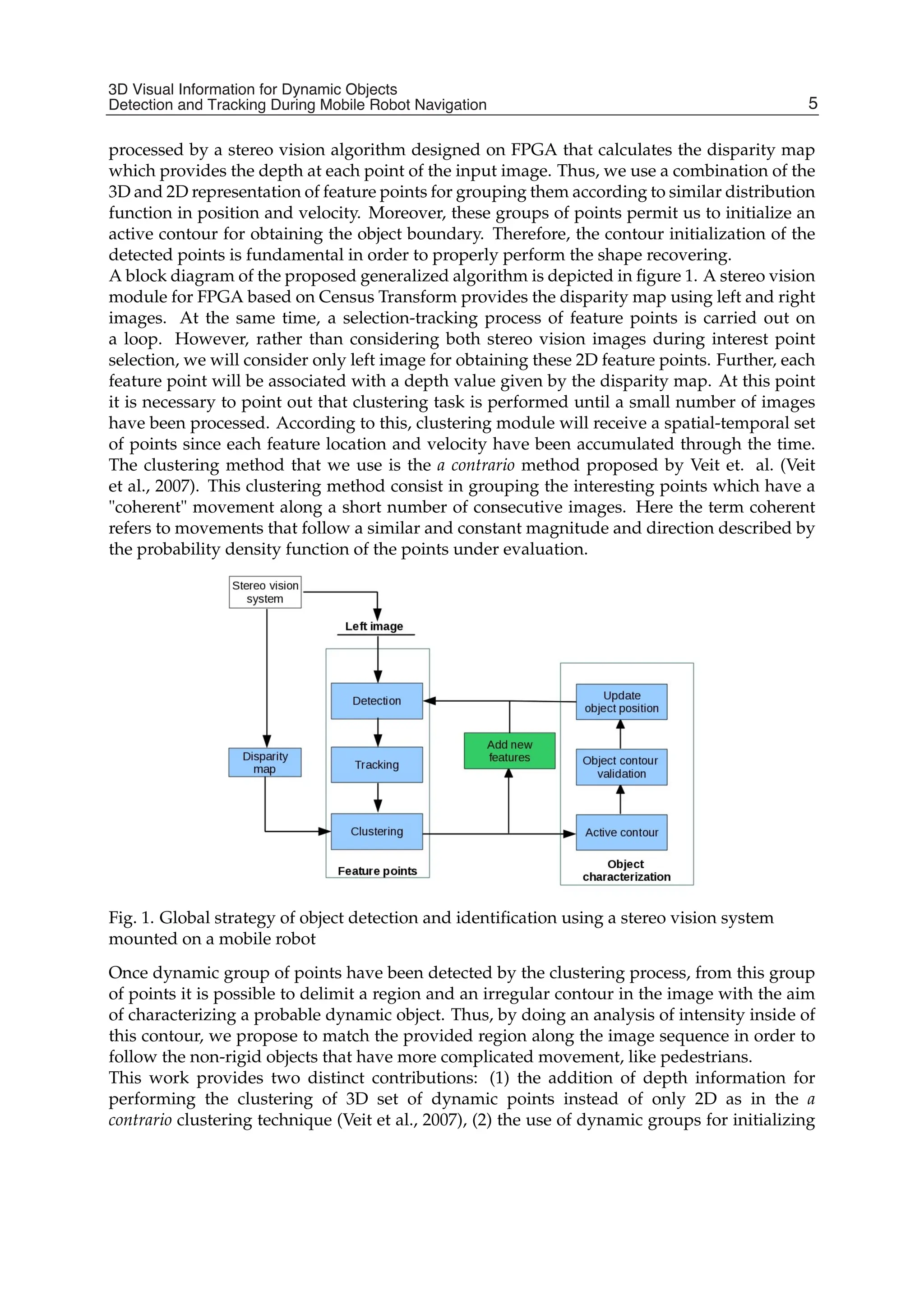


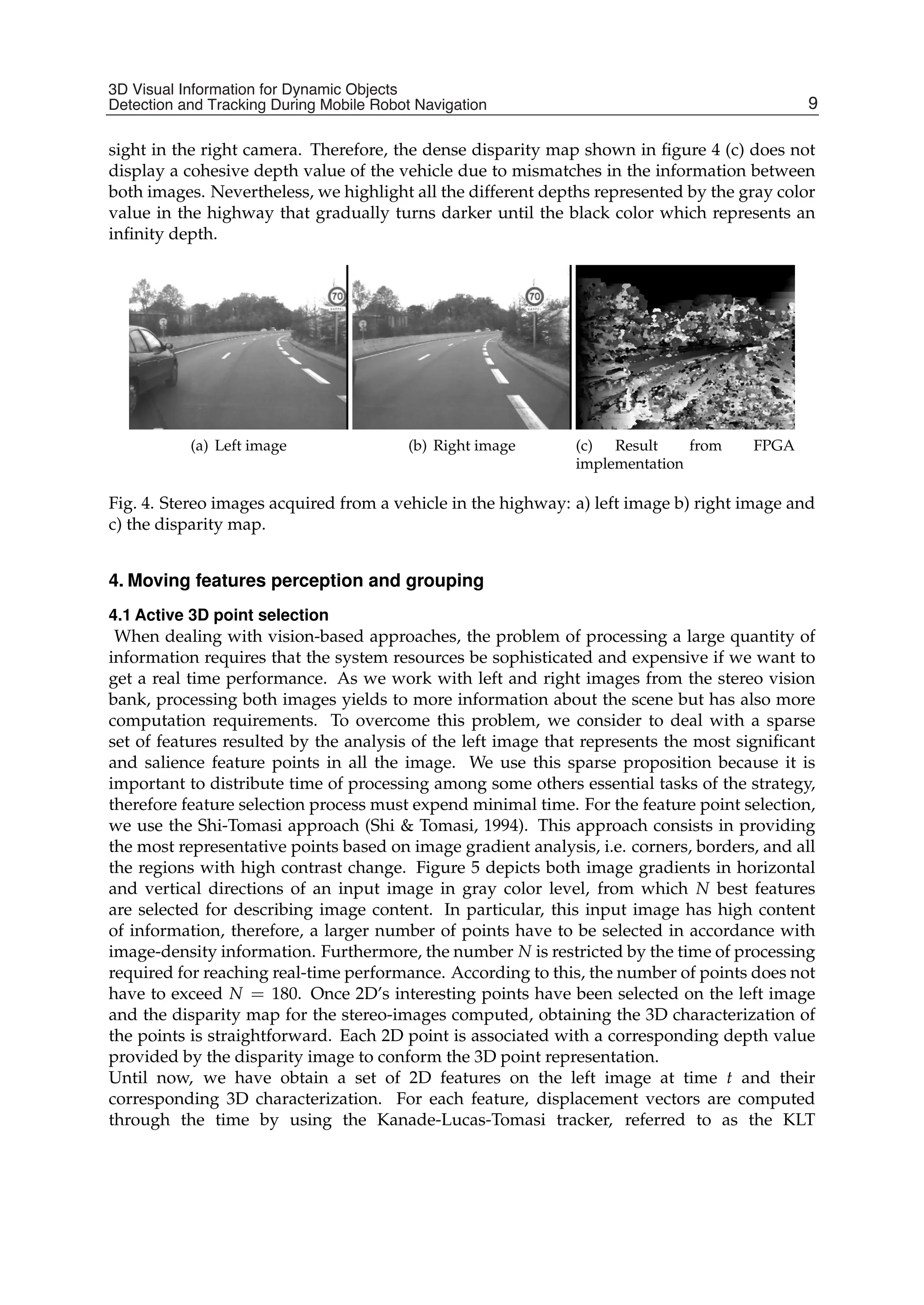


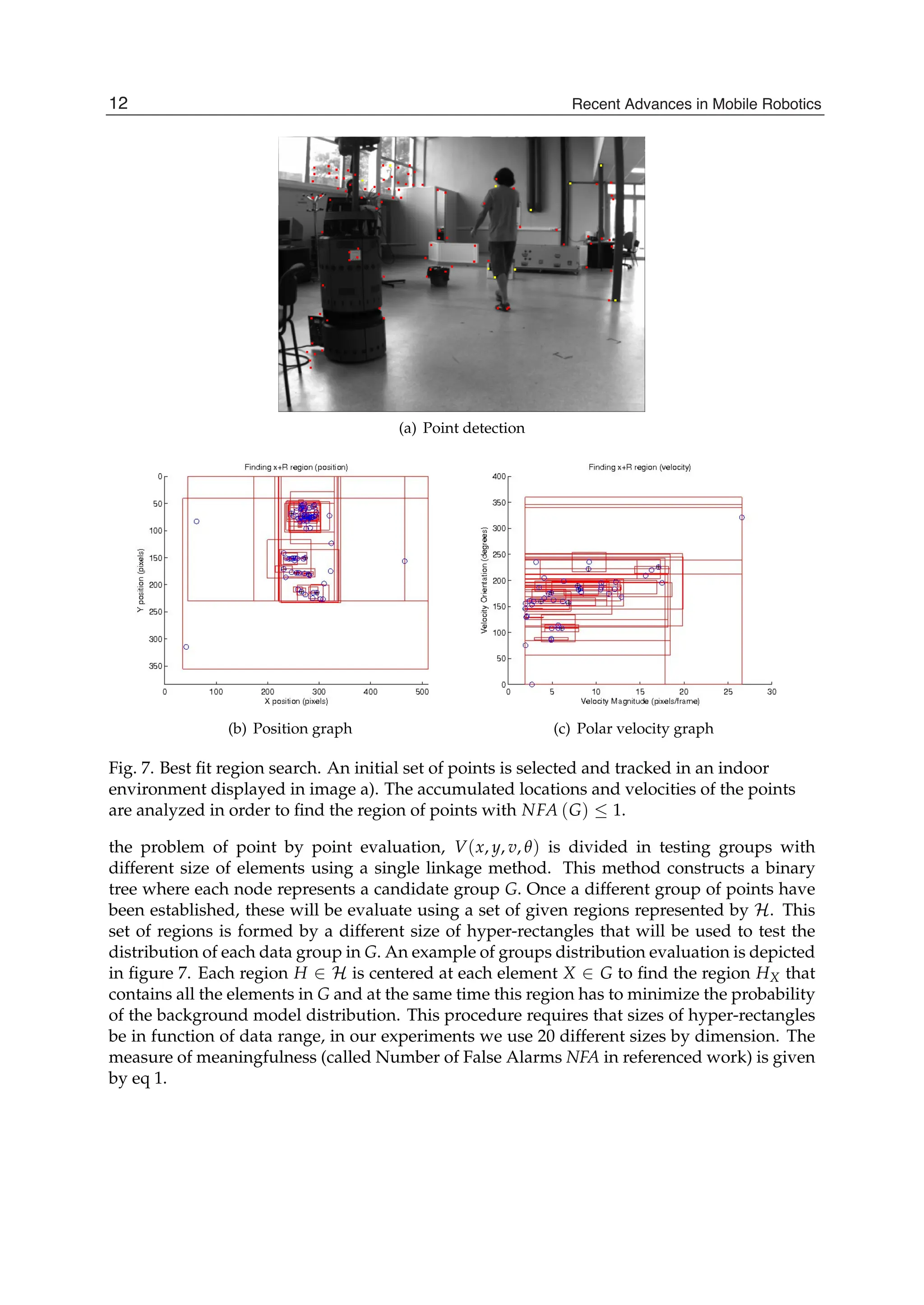


![3D Visual Information for Dynamic Objects Detection and Tracking During Mobile Robot Navigation 13
with feature points, here we describe a strategy for recovering the deformable shape of the
objects through the time by considering others features like intensity image gradient inside
of contour. Therefore, through this section we will describe fundamental details of the active
contours theory, and the object tracking procedure by means of the active contours.
5.1 Active contour initialization
The results obtained in section 4.2 allow the definition of an initial irregular contour that
contains totally or partially our interest object. To this end, we take an outer location of points
in the detected group for initializing an active contour which delimits the object on the image.
An example is displayed in figure 9 1: in image (a) a set of points dynamic (in blue) is detected
on which correspond to the person in motion on this sequence. From this set of points we
have selected those illustrated in color magenta to describe the object contour depicted in
yellow. Due to the fact these points are the most farthest from the center then they are the
most representative and closest to the object frontiers. For the results show in image 9(a), we
have 8 points on the curve and we use for each 4 control points. The value of 4 control points
is fixed for each point on the frontier in order to introduce the corners or discontinuities in the
curve (Marin-Hernandez, 2004). Initial contour will allow us to obtain a deformable model by
a bounded potential shown in figure 9(b). The zone occupied by the object (represented in red
color) is separated from the background. The most intens tones inside of the object are used
to best adapt initial contour to the actual object silhouette. Therefore, a more detailed object
shape is achieved by analyzing internal and external energy in a bounding box that contains
the initial contour.
(a) Initial contour of a non-rigid
object
(b) energy functional
Fig. 9. Test performed with real images acquired by a fixed camera in an indoor
environment. a)Initial contour derived from points further away from the center b) Energy
functional that concentrates internal and external energy considering the initial contour of a).
5.1.1 Parametric active contours.
At this point, it is necessary to represent the initial contour in 9 by a parametric curve u(τ) =
(x(τ), y(τ)), τ ∈ [0, 1], with u(0) = u(1). this contour is deformed through the time domain
to minimize the energy expressed by:
1 This image sequence was downloaded from the web site (Fisher, 2011) provided by EC Funded
CAVIAR project/IST 2001 37540
15
3D Visual Information for Dynamic Objects
Detection and Tracking During Mobile Robot Navigation](https://image.slidesharecdn.com/2057402-250604150432-f170e783/75/Recent-Advances-In-Mobile-Robotics-A-Topalov-31-2048.jpg)
![14 Will-be-set-by-IN-TECH
Esnake =
1
0
[Eint(u(τ)) + Eext(u(τ))] dτ (3)
where Eint is expressed by two main terms, the first one refers to the elasticity and the second
the flexibility, given:
Eint = α
1
0
|uτ(τ)|2
dτ + β
1
0
|uττ(τ)|2
dτ (4)
τ and ττ indexes in the term u(τ) implies respectively first and second order of derivation.
By returning to the equation 3 for defining the term Eext or the energy of the image (Sekhar
et al., 2008), as the field of potential P:
Eext =
1
0
P(u(τ))dτ (5)
The potential includes different terms defined from image proprieties like edges, lines, etc.
Edges energy is obtained by computing the magnitude of the gradient intensity |∇I|. Without
a good initialization, the energy of the edges will not be enough to locate the objects on
noisy or low contrast images. Therefore an additional potential of the regions is added to
the edge energy. Generally, the potential of the regions is defined by the mean (μ) and the
variance (σ2) of the pixels intensity in the region. However, other constraints could be added
like the object velocities, or other statistics derived from region characteristics (Brox et al.,
2010). Because of the real-time constraints, we calculate only some statistics in the region that
describe the object, such as the main properties to its implementation in correspondence to
the next image. The following section describes the proposed strategy about shape recovering
and object tracking using active contours.
5.2 Incremental silhouette definition
We have tested a method based on the work of Chan and Vese (Chan Vese, 2001) in order
to find the silhouette of the object. In this work, the authors give a region of initialization
which may contain total or partially the object. The analysis of this initial contour will allow
evaluation of the conditions of the energy minimization inside and outside of the contour.
An example of a shape recovering of a person in an indoor environment using the Chan and
Vese method is shown in figure 10. First row of images display the contour evolution. In the
second row the region inside of the contour for each corresponding above image is illustrated.
These images are given as input to the process for recovering real object contour. Furthermore,
white regions on these images are labeled as occupied locations which avoid the detection of
new interesting points inside of it through the time. According to this, new feature selection
(detailed in section 4.1) will look for unoccupied locations in the image allowing the detection
of incoming objects.
Once a partial contour at image t in figure 10 has been obtained by minimizing eq. 3, we
estimate its position at image t + 1 for starting a new convergence process. The prediction
of the region on the next image is always given by the Kalman filter. The vector state of our
object is expressed as:
x0 =
x̄, ȳ, v̄x, v̄y
T
(6)
Namely, x̄, ȳ denote the barycenter location and v̄x, v̄y the means of velocity vector in X
and Y direction respectively. Figure 11 illustrates an example of the filter prediction. The
barycenter position and the partial converged contour are located in accordance with Kalman
16 Recent Advances in Mobile Robotics](https://image.slidesharecdn.com/2057402-250604150432-f170e783/75/Recent-Advances-In-Mobile-Robotics-A-Topalov-32-2048.jpg)