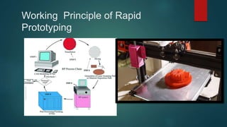
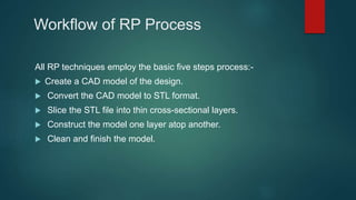
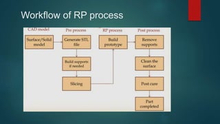
Rapid Prototyping
MADE BY :- PATEL PRINSKUMAR ASHOKBHAI 216310319004
HET PARESHKUMAR PATEL 216310319006
PATEL HARSH ARVINDBHAI 216310319060
PATEL KRUTIK HARESHKUMAR 226318319007
Inroduction
 In many fields, there is great uncertainty as to whether a new
design will actually do what is desired. New designs often
have unexpected problems. A prototype is often used as part
of the product design process to allow engineers and
designers the ability to explore design alternatives, test
theories and confirm performance prior to starting production
of a new product. Engineers use their experience to tailor the
prototype according to the specific unknowns still present in
the intended design.
defination
 Rapid Prototyping technology employs various engineering e.g.
computer control and software techniques including laser, optical scanning,
photosensitive polymers, material extrusion and deposition, powder metallurgy
etc. to directly produce a physical model layer by layer (Layer Manufacturing) in
accordance with the geometrical data delivered from a 3D CAD model.
Working Principle of Rapid
Prototyping
 Rapid Prototyping uses a standard data interface, implemented as the STL
file format, to translate from the CAD software to the 3D prototyping
machine. The STL file approximates the shape of a part or assembly using
triangular facets. Typically, Rapid Prototyping systems can produce 3D
models within a few hours.
Why Rapid Prototyping
 Prototyping can improve the quality of requirements and specifications
provided to developers.
 Reduced time and costs.
 Users are actively involved in the development.
 Quicker user feedback is available leading to better solutions.
 Errors can be detected much earlier.
 Missing functionality can be identified easily
Limitation of Rapid Prototyping
 High precision RP machines are still expensive.
 ca RP systems are difficult to build parts with accuracy under +/-0.02mm
and wall thickness under 0.5mm.
 The physical properties of the RP parts are normally inferior to those
samples that made in proper materials and by the traditional tooling.
 The RP parts are not comparable to (CNC) prototype parts in the surface
finishing, strength, elasticity, reflective index and other material physical
properties
Workflow of RP Process
All RP techniques employ the basic five steps process:-
 Create a CAD model of the design.
 Convert the CAD model to STL format.
 Slice the STL file into thin cross-sectional layers.
 Construct the model one layer atop another.
 Clean and finish the model.
Workflow of RP process
CAD Model Creation
 First, the object to be built is modeled using a Computer-Aided Design
(CAD) software package.
 Solid modelers, such as Pro/ENGINEER, tend to represent 3-D objects
more accurately than wire-frame modelers such as AutoCAD, and will
therefore yield better results.
 This process is identical for all of the RP build techniques.
Conversion to STL Format
 To establish consistency, the STL format has been adopted as the
standard of the rapid prototyping industry.
 The second step, therefore, is to convert the CAD file into STL format. This
format represents a three-dimensional surface as an assembly of planar
triangles
 STL files use planar elements, they cannot represent curved surfaces
exactly. Increasing the number of triangles improves the approximation
Example of STL model
This figure shows a typical example of STL
model which is composed of triangles
And each triangle is described by a
Unit normal vector direction and three
points representing the vertices of
The triangle
Slice the STL file
 In the third step, a pre-processing program prepares the STL file to be
built.
 The pre-processing software slices the STL model into a number of layers
from 0.01 mm to 0.7 mm thick, depending on the build technique.
 "The program may also generate an auxiliary structure to support the
model during the build. Supports are useful for delicate features such as
overhangs, internal cavities, and thin-walled sections.
Layer by Construction
 The fourth step is the actual construction of the part.
 RP machines build one layer at a time from polymers, paper, or powdered
metal.
 Most machines are fairly autonomous, needing little human intervention.
Clean and Finish
 The final step is post-processing. This involves removing the prototype
from the machine and detaching any supports.
 Some photosensitive materials need to be fully cured before uses
 Prototypes may also require minor cleaning and surface treatment.
 Sanding, sealing, and/or painting the model will improve its appearance
and durability.
Types of Rapid Prototyping
Technologies
 SLA-Stereolithography
 SLS-Selective Laser Sintering
 LOM-Laminated Object Manufacturing
 FDM-Fused Deposition Modeling
 3DP Three Dimensional Printing
Advantage of RP
 Reduced design & development time.
 Reduced overall product development cost.
 Elimination or reduction of risk.
 Allows functionality testing at a fraction of the cost.
 Improved and increased user involvement during design stages of NPD.
 Ability to evaluate human factors and ergonomics.
Disadvantage
 Lack of accuracy.
 Added initial costs.
 Some rapid prototyping processes are still expensive and not economical.
 Reduced material properties like surface finish and strength.
 Rapid prototyping required skilled labour
 Limited material range.
 Overlooking some key features because they cannot be prototyped affects
the prototype testing.
 End-user confusion, customers mistaking it for the finished
project/developer misunderstanding of user objectives.
Application of RP
 Visual prototypes
 Concept models
 Functional prototypes
 Pre-production prototypes
 Production tools prototypes
 Production moulds for prototypes

rapid prototyping ppt.pptx

  • 1.
    Rapid Prototyping MADE BY:- PATEL PRINSKUMAR ASHOKBHAI 216310319004 HET PARESHKUMAR PATEL 216310319006 PATEL HARSH ARVINDBHAI 216310319060 PATEL KRUTIK HARESHKUMAR 226318319007
  • 2.
    Inroduction  In manyfields, there is great uncertainty as to whether a new design will actually do what is desired. New designs often have unexpected problems. A prototype is often used as part of the product design process to allow engineers and designers the ability to explore design alternatives, test theories and confirm performance prior to starting production of a new product. Engineers use their experience to tailor the prototype according to the specific unknowns still present in the intended design.
  • 3.
    defination  Rapid Prototypingtechnology employs various engineering e.g. computer control and software techniques including laser, optical scanning, photosensitive polymers, material extrusion and deposition, powder metallurgy etc. to directly produce a physical model layer by layer (Layer Manufacturing) in accordance with the geometrical data delivered from a 3D CAD model.
  • 4.
    Working Principle ofRapid Prototyping
  • 5.
     Rapid Prototypinguses a standard data interface, implemented as the STL file format, to translate from the CAD software to the 3D prototyping machine. The STL file approximates the shape of a part or assembly using triangular facets. Typically, Rapid Prototyping systems can produce 3D models within a few hours.
  • 6.
    Why Rapid Prototyping Prototyping can improve the quality of requirements and specifications provided to developers.  Reduced time and costs.  Users are actively involved in the development.  Quicker user feedback is available leading to better solutions.  Errors can be detected much earlier.  Missing functionality can be identified easily
  • 7.
    Limitation of RapidPrototyping  High precision RP machines are still expensive.  ca RP systems are difficult to build parts with accuracy under +/-0.02mm and wall thickness under 0.5mm.  The physical properties of the RP parts are normally inferior to those samples that made in proper materials and by the traditional tooling.  The RP parts are not comparable to (CNC) prototype parts in the surface finishing, strength, elasticity, reflective index and other material physical properties
  • 8.
    Workflow of RPProcess All RP techniques employ the basic five steps process:-  Create a CAD model of the design.  Convert the CAD model to STL format.  Slice the STL file into thin cross-sectional layers.  Construct the model one layer atop another.  Clean and finish the model.
  • 9.
  • 10.
    CAD Model Creation First, the object to be built is modeled using a Computer-Aided Design (CAD) software package.  Solid modelers, such as Pro/ENGINEER, tend to represent 3-D objects more accurately than wire-frame modelers such as AutoCAD, and will therefore yield better results.  This process is identical for all of the RP build techniques.
  • 11.
    Conversion to STLFormat  To establish consistency, the STL format has been adopted as the standard of the rapid prototyping industry.  The second step, therefore, is to convert the CAD file into STL format. This format represents a three-dimensional surface as an assembly of planar triangles  STL files use planar elements, they cannot represent curved surfaces exactly. Increasing the number of triangles improves the approximation
  • 12.
    Example of STLmodel This figure shows a typical example of STL model which is composed of triangles And each triangle is described by a Unit normal vector direction and three points representing the vertices of The triangle
  • 13.
    Slice the STLfile  In the third step, a pre-processing program prepares the STL file to be built.  The pre-processing software slices the STL model into a number of layers from 0.01 mm to 0.7 mm thick, depending on the build technique.  "The program may also generate an auxiliary structure to support the model during the build. Supports are useful for delicate features such as overhangs, internal cavities, and thin-walled sections.
  • 15.
    Layer by Construction The fourth step is the actual construction of the part.  RP machines build one layer at a time from polymers, paper, or powdered metal.  Most machines are fairly autonomous, needing little human intervention.
  • 16.
    Clean and Finish The final step is post-processing. This involves removing the prototype from the machine and detaching any supports.  Some photosensitive materials need to be fully cured before uses  Prototypes may also require minor cleaning and surface treatment.  Sanding, sealing, and/or painting the model will improve its appearance and durability.
  • 17.
    Types of RapidPrototyping Technologies  SLA-Stereolithography  SLS-Selective Laser Sintering  LOM-Laminated Object Manufacturing  FDM-Fused Deposition Modeling  3DP Three Dimensional Printing
  • 18.
    Advantage of RP Reduced design & development time.  Reduced overall product development cost.  Elimination or reduction of risk.  Allows functionality testing at a fraction of the cost.  Improved and increased user involvement during design stages of NPD.  Ability to evaluate human factors and ergonomics.
  • 19.
    Disadvantage  Lack ofaccuracy.  Added initial costs.  Some rapid prototyping processes are still expensive and not economical.  Reduced material properties like surface finish and strength.  Rapid prototyping required skilled labour  Limited material range.  Overlooking some key features because they cannot be prototyped affects the prototype testing.  End-user confusion, customers mistaking it for the finished project/developer misunderstanding of user objectives.
  • 20.
    Application of RP Visual prototypes  Concept models  Functional prototypes  Pre-production prototypes  Production tools prototypes  Production moulds for prototypes