DEFINITION
DEFINITION
Pump is amechanical device to increase the
Pump is a mechanical device to increase the
pressure energy of a liquid with the help of a
pressure energy of a liquid with the help of a
prime mover to enable it to impart energy to the
prime mover to enable it to impart energy to the
liquid.
liquid.
In most of the cases pump is used for raising liquid
In most of the cases pump is used for raising liquid
from a lower to a higher level.
from a lower to a higher level.
This is achieved by creating a low pressure at the
This is achieved by creating a low pressure at the
suction end and high pressure at the delivery end
suction end and high pressure at the delivery end
of the pump.
of the pump.
3.
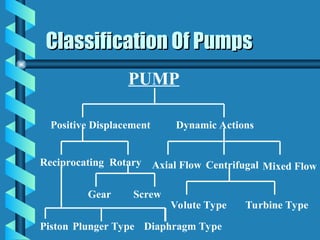
PUMP
Positive Displacement DynamicActions
Reciprocating Rotary
Gear Screw
Piston Plunger Type
Axial Flow Centrifugal Mixed Flow
Volute Type Turbine Type
Classification Of Pumps
Classification Of Pumps
Diaphragm Type
4.
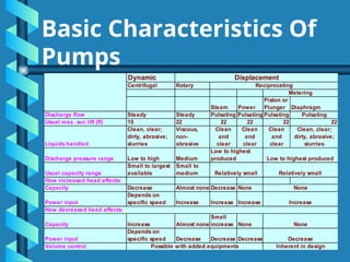
Dynamic
Centrifugal Rotary
Steam Power
Pistonor
Plunger Diaphragm
Discharge flow Steady Steady Pulsating Pulsating Pulsating Pulsating
Usual max. suc lift (ft) 15 22 22 22 22 22
Liquids handled
Clean, clear;
dirty, abrasive;
slurries
Viscous,
non-
abrasive
Clean
and
clear
Clean
and
clear
Clean
and
clear
Clean, clear;
dirty, abrasive;
slurries
Discharge pressure range Low to high Medium
Usual capacity range
Small to largest
available
Small to
medium
How increased head affects:
Capacity Decrease Almost none Decrease None
Power input
Depends on
specific speed Increase Increase Increase
How decreased head affects:
Capacity Increase Almost none
Small
increase None
Power input
Depends on
specific speed Decrease Decrease Decrease
Volume control
Displacement
Metering
Low to highest
produced Low to highest produced
None
Decrease
Possible with added equipments Inherent in design
Relatively small Relatively small
None
Increase
Reciprocating
Basic Characteristics Of
Pumps
5.
Reciprocating Pump
Reciprocating Pump
Areciprocating pump is a positive
A reciprocating pump is a positive
displacement mechanism with liquid
displacement mechanism with liquid
displacement pressure being limited only
displacement pressure being limited only
by the strength of the structural parts.
by the strength of the structural parts.
Liquid volume or capacity delivered is
Liquid volume or capacity delivered is
constant regardless of pressure and is
constant regardless of pressure and is
varied only by speed changing.
varied only by speed changing.
Contd.
6.
Reciprocating Pump
Reciprocating Pump
Characteristicsof a Reciprocating pump are
Characteristics of a Reciprocating pump are:
:
1.
1. Positive displacement of liquid.
Positive displacement of liquid.
2.
2. High pulsations caused by the sinusoidal
High pulsations caused by the sinusoidal
motion of the piston.
motion of the piston.
3.
3. High volumetric efficiency.
High volumetric efficiency.
Type Of ReciprocatingPump
Type Of Reciprocating Pump
1.
1. Piston Pump
Piston Pump: The piston is driven by a
: The piston is driven by a
crank mechanism. The forward and
crank mechanism. The forward and
backward (in case of double acting)
backward (in case of double acting)
travel of the piston displaces the liquid
travel of the piston displaces the liquid
out the discharge check valve. Packing
out the discharge check valve. Packing
leakage is unavoidable.
leakage is unavoidable.
Contd.
9.
Type Of ReciprocatingPump
Type Of Reciprocating Pump
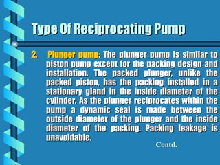
2.
2. Plunger pump
Plunger pump: The plunger pump is similar to
: The plunger pump is similar to
piston pump except for the packing design and
piston pump except for the packing design and
installation. The packed plunger, unlike the
installation. The packed plunger, unlike the
packed piston, has the packing installed in a
packed piston, has the packing installed in a
stationary gland in the inside diameter of the
stationary gland in the inside diameter of the
cylinder. As the plunger reciprocates within the
cylinder. As the plunger reciprocates within the
pump a dynamic seal is made between the
pump a dynamic seal is made between the
outside diameter of the plunger and the inside
outside diameter of the plunger and the inside
diameter of the packing. Packing leakage is
diameter of the packing. Packing leakage is
unavoidable.
unavoidable.
Contd.
10.
Type Of ReciprocatingPump
Type Of Reciprocating Pump
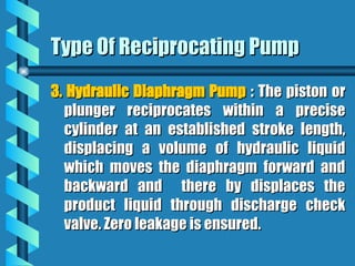
3.
3. Hydraulic Diaphragm Pump
Hydraulic Diaphragm Pump : The piston or
: The piston or
plunger reciprocates within a precise
plunger reciprocates within a precise
cylinder at an established stroke length,
cylinder at an established stroke length,
displacing a volume of hydraulic liquid
displacing a volume of hydraulic liquid
which moves the diaphragm forward and
which moves the diaphragm forward and
backward and there by displaces the
backward and there by displaces the
product liquid through discharge check
product liquid through discharge check
valve. Zero leakage is ensured.
valve. Zero leakage is ensured.
‘
‘PCT’ Pulsation ControlTool
PCT’ Pulsation Control Tool
Pulsation Control Tool (PCT), often referred
Pulsation Control Tool (PCT), often referred
to as “Dampeners” or “Stabilizers”, are used
to as “Dampeners” or “Stabilizers”, are used
on the inlet and discharge piping to
on the inlet and discharge piping to
stabilize the liquid-flow and to protect the
stabilize the liquid-flow and to protect the
pumping mechanism and associated
pumping mechanism and associated
piping by reducing the high pulsation
piping by reducing the high pulsation
within the liquid caused by the motions of
within the liquid caused by the motions of
slider-crank mechanism.
slider-crank mechanism.
14.
Type Of RotaryPositive
Type Of Rotary Positive
Displacement Pump
Displacement Pump
1.
1. Single Screw Pump
Single Screw Pump: The liquid is carried
: The liquid is carried
between the rotor screw threads and axially
between the rotor screw threads and axially
displaced as the rotor threads mesh with
displaced as the rotor threads mesh with
internal threads on the stator.
internal threads on the stator.
2.
2. Multi Screw Pump
Multi Screw Pump: Intermeshing screws are
: Intermeshing screws are
located in close fitting casing. Screws and
located in close fitting casing. Screws and
casing form perfectly sealed chambers. The
casing form perfectly sealed chambers. The
materials confined in these chamber is
materials confined in these chamber is
continuously advanced.
continuously advanced.
Contd..
Type Of RotaryPositive
Type Of Rotary Positive
Displacement Pump
Displacement Pump
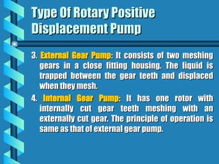
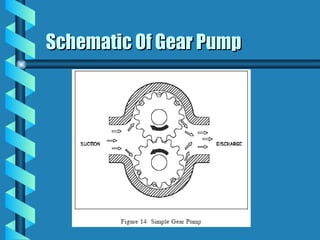
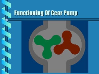
3.
3. External Gear Pump
External Gear Pump: It consists of two meshing
: It consists of two meshing
gears in a close fitting housing. The liquid is
gears in a close fitting housing. The liquid is
trapped between the gear teeth and displaced
trapped between the gear teeth and displaced
when they mesh.
when they mesh.
4.
4. Internal Gear Pump
Internal Gear Pump: It has one rotor with
: It has one rotor with
internally cut gear teeth meshing with an
internally cut gear teeth meshing with an
externally cut gear. The principle of operation is
externally cut gear. The principle of operation is
same as that of external gear pump.
same as that of external gear pump.
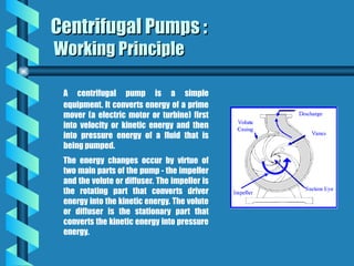
A centrifugal pumpis a simple
equipment. It converts energy of a prime
mover (a electric motor or turbine) first
into velocity or kinetic energy and then
into pressure energy of a fluid that is
being pumped.
The energy changes occur by virtue of
two main parts of the pump - the impeller
and the volute or diffuser. The impeller is
the rotating part that converts driver
energy into the kinetic energy. The volute
or diffuser is the stationary part that
converts the kinetic energy into pressure
energy.
Centrifugal Pumps :
Centrifugal Pumps :
Working Principle
Working Principle
21.
Centrifugal Pump
Centrifugal Pump
ApplicableStandard:
Applicable Standard:
API-610, Centrifugal pumps in petroleum,
API-610, Centrifugal pumps in petroleum,
chemical and gas industry.
chemical and gas industry.
22.
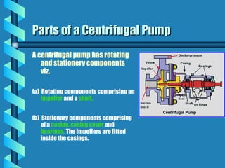
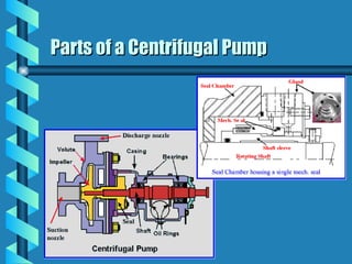
A centrifugal pumphas rotating
and stationery components
viz.
(a) Rotating components comprising an
impeller and a shaft.
(b) Stationary components comprising
of a casing, casing cover and
bearings. The impellers are fitted
inside the casings.
Parts of a Centrifugal Pump
Parts of a Centrifugal Pump
23.
Applications in differentIndustries
Applications in different Industries
Industrial Water Supply
Industrial Water Supply
• Process
Process
• Utility
Utility
• Fire-fighting
Fire-fighting
• Cooling
Cooling
• Circulating Systems
Circulating Systems
• De-watering & Drainage
De-watering & Drainage
Municipal Applications
Municipal Applications
• Water Supply
Water Supply
• Sewerage
Sewerage
• Storm Water
Storm Water
• Waste Water Treatment
Waste Water Treatment
Irrigation
Irrigation
• Sprinkler System
Sprinkler System
24.
Chemical &Petrochemical Handling
Chemical & Petrochemical Handling
• Brine
Brine
• Alkaline solutions
Alkaline solutions
• Corrosive acids
Corrosive acids
• Benzene
Benzene
• Hydro-carbons
Hydro-carbons
• Oils
Oils
• Gaseous liquids
Gaseous liquids
• LPG
LPG
Naval & Marine Applications
Naval & Marine Applications
• Saline Water
Saline Water
• Petroleum Products
Petroleum Products
and much much more
and much much more
Applications in different Industries
Applications in different Industries
(continued)
(continued)
25.
Centrifugal Pumps -Performance
Centrifugal Pumps - Performance
Parameters
Parameters
The key performance parameters of centrifugal
pumps are :
• Capacity,
• Head,
• BHP (Brake Horse Power),
• BEP (Best Efficiency Point),
• NPSH, and
• Specific Speed.
26.
Centrifugal Pumps :Parameters :
Centrifugal Pumps : Parameters :
Effects of Capacity & Head Fluctuations
Effects of Capacity & Head Fluctuations
A centrifugal pump operating at a lower capacity than its is designed for may result in :
a) cavitation
b) Heavy leakages from the casing, seal, and stuffing box
c) Deflection and shearing of shafts
d) Seizure of pump internals
e) Close tolerances erosion
f) Separation cavitation
g) Product quality degradation
f) Excessive hydraulic thrust
g) Premature bearing failures
Effects of Operating a Pump at a different combination of capacity and head
than that it has been designed for.
27.
Centrifugal Pumps :Parameters :
Centrifugal Pumps : Parameters :
Power & Efficiency
Power & Efficiency
BHP , WHP and Pump Efficiency
BHP , WHP and Pump Efficiency
Pump input or brake horsepower (BHP) is the actual horsepower delivered to
the pump shaft by the drive.
Pump output or hydraulic or water horsepower (WHP) is the liquid
horsepower delivered by the pump. These two terms are defined by the
following formulas.
28.
Centrifugal Pumps :Parameters :
Centrifugal Pumps : Parameters :
BEP
BEP
BEP and its Significance
BEP and its Significance
Best Efficiency Point (BEP) is the capacity , for a particular impeller diameter, at which the
efficiency of the pump is highest at that impeller diameter. All points to the right or left of
BEP have a lower efficiency.
BEP as a measure of optimum energy conversion
It is imperative that the pump should be decided so that its duty point is at or very near to
the BEP, so as to minimize the energy cost.
BEP as a measure of mechanically stable operation
Operations in zones considerably remote from the BEP may lead to premature bearing and
mechanical seal failures due to shaft deflection, and an increase in temperature of the
process fluid in the pump casing causing seizure of close tolerance parts and cavitation.
29.
Centrifugal Pumps :Parameters :
Centrifugal Pumps : Parameters :
NPSH
NPSH
NPSH and its Significance
NPSH and its Significance
Net Positive Suction Head Available (NPSHa) is the net head available at the suction flange
of the pump.
NPSHa = (Barometric Head) ± (Static Head) - (Vapour Pressure of the liquid being
pumped) - (Pipe / Valve Friction Losses in the Suction Side)
Net Positive Suction Head Required (NPSHr) is the net head required at the suction flange
of the pump for the pump to operate properly. It depends on the pump design and
generally increases with the capacity of the pump.
NPSHa must be greater than NPSHr
to allow proper functioning of the pumping system
as well as to prevent cavitation.
30.
Cavitation
Cavitation
The formation andsubsequent collapse of vapor
The formation and subsequent collapse of vapor
filled cavities in a liquid due to dynamic action is
filled cavities in a liquid due to dynamic action is
called cavitations.
called cavitations.
The cavities may be vapor filled pockets or bubbles
The cavities may be vapor filled pockets or bubbles
or a combination of both.
or a combination of both.
The local pressure must be at or lower than the
The local pressure must be at or lower than the
vapor pressure of liquid for cavitation to begin
vapor pressure of liquid for cavitation to begin
and the cavities must encounter a region of
and the cavities must encounter a region of
pressure higher than vapour pressure in order to
pressure higher than vapour pressure in order to
collapse.
collapse.
31.
Cavitation
Cavitation
It has thefollowing effects:
It has the following effects:
1.
1. A reduction in the pump capacity.
A reduction in the pump capacity.
2.
2. A reduction in the head of the pump.
A reduction in the head of the pump.
3.
3. Excessive pump vibration.
Excessive pump vibration.
4.
4. A noise that can be heard when the pump
A noise that can be heard when the pump
is running.
is running.
5.
5. Damage that can be seen on the pump
Damage that can be seen on the pump
impeller and volute.
impeller and volute.
32.
Centrifugal Pumps :Parameters :
Centrifugal Pumps : Parameters :
Capacity
Capacity
Defining Capacity of Pumps
Defining Capacity of Pumps
Capacity means the flow rate with which liquid is moved or pushed by the
pump to the desired point in the process. It is commonly measured in either
gallons per minute (gpm) or cubic meters per hour (m3
/hr).
The quantity of liquid to be handled is one of the most
important criterion in selecting a particular pump.
This primarily affects the size of the pump and
determines whether it is desirable to use a number of
pumps in parallel.
The capacity of a pump usually changes with the
changes in operation of the process. For example, for
a centrifugal pump, it increases with the decrease in
system pressure requirements and vice-versa.
33.
Centrifugal Pumps :Parameters :
Centrifugal Pumps : Parameters :
Head
Head
Defining Head of Pumps
Defining Head of Pumps
Head
Head is a measurement of the pressure developed by the pumps. In other
is a measurement of the pressure developed by the pumps. In other
words, it is the measurement of the height of a vertical liquid column that
words, it is the measurement of the height of a vertical liquid column that
the pump could create from the kinetic energy imparted to the liquid.
the pump could create from the kinetic energy imparted to the liquid.
Total Head (H) of a Centrifugal Pump consists of :
Static Head (S) : which is the difference between the
liquid suction level to the discharge level of the liquid.
Dynamic Head (D) : which includes the frictional losses
in the pipeline & valves due to flow of the liquid (F) +
pressure required at the point of delivery (P)
Thus H = S + { F + P }
The suitability of a centrifugal pump and the number of
stages required will largely be determined by this
factor.
34.
Centrifugal Pumps :Parameters :
Centrifugal Pumps : Parameters :
Capacity & Head Combination
Capacity & Head Combination
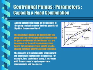
A pump selection is based on the capacity of
the pump to discharge the desired quantity of
liquid at the required head.
The quantity of liquid to be delivered by the
pump and the corresponding head which will
be generated due to friction losses etc. are
dependent on the entire pumping system.
Hence, the pumping system should also be
studied carefully before selecting the pump.
The capacity of a pump usually changes with
the changes in operation of the process. For
example, for a centrifugal pump, it increases
with the decrease in system pressure
requirements and vice-versa.
35.
Centrifugal Pumps :Parameters :
Centrifugal Pumps : Parameters :
Effects of Capacity & Head Fluctuations
Effects of Capacity & Head Fluctuations
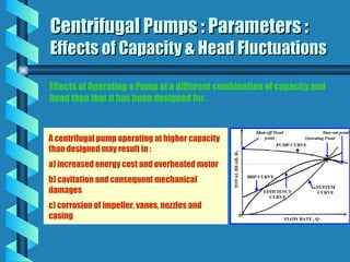
A centrifugal pump operating at higher capacity
than designed may result in :
a) increased energy cost and overheated motor
b) cavitation and consequent mechanical
damages
c) corrosion of impeller, vanes, nozzles and
casing
Effects of Operating a Pump at a different combination of capacity and
head than that it has been designed for.
36.
Change of Performance
Changeof Performance
With same casing we can do the following
With same casing we can do the following:
:
1.
1. Trimming the pump impeller
Trimming the pump impeller
2.
2. Removing metal from tips of impeller vanes
Removing metal from tips of impeller vanes
3.
3. Providing vanes with same angularity but
Providing vanes with same angularity but
different width
different width
4.
4. Orificing the pump discharge
Orificing the pump discharge
5.
5. Providing impeller with different number of
Providing impeller with different number of
vanes and different discharge angle
vanes and different discharge angle
Contd.
37.
Change of performance
Changeof performance
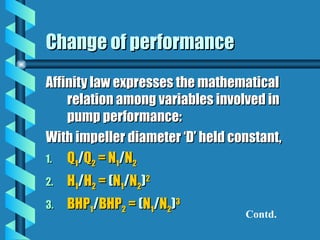
Affinity law expresses the mathematical
Affinity law expresses the mathematical
relation among variables involved in
relation among variables involved in
pump performance:
pump performance:
With impeller diameter ‘D’ held constant,
With impeller diameter ‘D’ held constant,
1.
1. Q
Q1
1/
/Q
Q2
2 = N
= N1
1/
/N
N2
2
2.
2. H
H1
1/
/H
H2
2 =
= (
(N
N1
1/
/N
N2
2)
)2
2
3.
3. BHP
BHP1
1/
/BHP
BHP2
2 =
= (
(N
N1
1/
/N
N2
2)
)3
3
Contd.
38.
Change of performance
Changeof performance
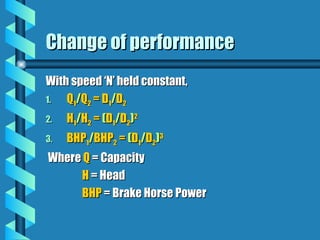
With speed ‘N’ held constant,
With speed ‘N’ held constant,
1.
1. Q
Q1
1/
/Q
Q2
2 = D
= D1
1/
/D
D2
2
2.
2. H
H1
1/
/H
H2
2 =
= (
(D
D1
1/
/D
D2
2)
)2
2
3.
3. BHP
BHP1
1/
/BHP
BHP2
2 =
= (
(D
D1
1/
/D
D2
2)
)3
3
Where
Where Q
Q = Capacity
= Capacity
H
H = Head
= Head
BHP
BHP = Brake Horse Power
= Brake Horse Power
39.
Selecting
Selecting a Pump-
a Pump -
Material of Construction (MOC)
Material of Construction (MOC)
Proper selection of
Proper selection of Material of Construction (MOC)
Material of Construction (MOC) of different
of different
components of a pump is one of the most important criterion for
components of a pump is one of the most important criterion for
the
the life
life of a pumping system.
of a pumping system.
Life
Life is the total number of hours of operation before one or more
is the total number of hours of operation before one or more
pump components are to be replaced to maintain an acceptable
pump components are to be replaced to maintain an acceptable
performance of the pump.
performance of the pump.
Life is primarily a measure of the resistance of the MOC of different
Life is primarily a measure of the resistance of the MOC of different
components to corrosion, erosion, or a combination of both
components to corrosion, erosion, or a combination of both
under operating conditions.
under operating conditions.
40.
Selecting
Selecting a Pump-
a Pump -
Material of Construction (MOC) : Impeller
Material of Construction (MOC) : Impeller
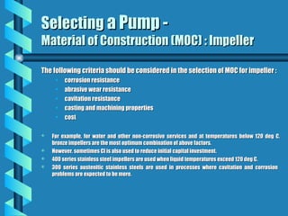
The following criteria should be considered in the selection of MOC for impeller :
The following criteria should be considered in the selection of MOC for impeller :
• corrosion resistance
corrosion resistance
• abrasive wear resistance
abrasive wear resistance
• cavitation resistance
cavitation resistance
• casting and machining properties
casting and machining properties
• cost
cost
For example, for water and other non-corrosive services and at temperatures below 120 deg C,
For example, for water and other non-corrosive services and at temperatures below 120 deg C,
bronze impellers are the most optimum combination of above factors.
bronze impellers are the most optimum combination of above factors.
However, sometimes CI is also used to reduce initial capital investment.
However, sometimes CI is also used to reduce initial capital investment.
400 series stainless steel impellers are used when liquid temperatures exceed 120 deg C.
400 series stainless steel impellers are used when liquid temperatures exceed 120 deg C.
300 series austenitic stainless steels are used in processes where cavitation and corrosion
300 series austenitic stainless steels are used in processes where cavitation and corrosion
problems are expected to be more.
problems are expected to be more.
41.
Selecting
Selecting a Pump-
a Pump -
Material of Construction (MOC) : Casings
Material of Construction (MOC) : Casings
The following criteria should be considered in the selection of MOC for Casings :
The following criteria should be considered in the selection of MOC for Casings :
• strength
strength
• corrosion resistance
corrosion resistance
• abrasive wear resistance
abrasive wear resistance
• casting and machining properties
casting and machining properties
• cost
cost
For most single stage pumping applications, cast iron is the preferred material for pump casings.
For most single stage pumping applications, cast iron is the preferred material for pump casings.
For temperatures above 175 deg C and discharge pressures higher than 13.8 mPa, cast steel is used.
For temperatures above 175 deg C and discharge pressures higher than 13.8 mPa, cast steel is used.
Cast steel or cast stainless steel are also preferable in case of corrosive and volatile petroleum
Cast steel or cast stainless steel are also preferable in case of corrosive and volatile petroleum
products.
products.
42.
Selecting
Selecting a Pump-
a Pump -
Material of Construction (MOC) : Shafts
Material of Construction (MOC) : Shafts
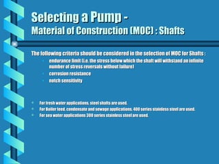
The following criteria should be considered in the selection of MOC for Shafts :
The following criteria should be considered in the selection of MOC for Shafts :
• endurance limit (i.e. the stress below which the shaft will withstand an infinite
endurance limit (i.e. the stress below which the shaft will withstand an infinite
number of stress reversals without failure)
number of stress reversals without failure)
• corrosion resistance
corrosion resistance
• notch sensitivity
notch sensitivity
For fresh water applications, steel shafts are used.
For fresh water applications, steel shafts are used.
For Boiler feed, condensate and sewage applications, 400 series stainless steel are used.
For Boiler feed, condensate and sewage applications, 400 series stainless steel are used.
For sea water applications 300 series stainless steel are used.
For sea water applications 300 series stainless steel are used.
43.
Selecting
Selecting a Pump-
a Pump -
Material of Construction (MOC) : Wearing Rings
Material of Construction (MOC) : Wearing Rings
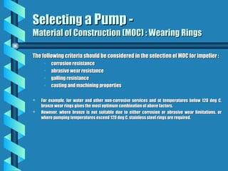
The following criteria should be considered in the selection of MOC for impeller :
The following criteria should be considered in the selection of MOC for impeller :
• corrosion resistance
corrosion resistance
• abrasive wear resistance
abrasive wear resistance
• galling resistance
galling resistance
• casting and machining properties
casting and machining properties
For example, for water and other non-corrosive services and at temperatures below 120 deg C,
For example, for water and other non-corrosive services and at temperatures below 120 deg C,
bronze wear rings gives the most optimum combination of above factors.
bronze wear rings gives the most optimum combination of above factors.
However, where bronze is not suitable due to either corrosion or abrasive wear limitations, or
However, where bronze is not suitable due to either corrosion or abrasive wear limitations, or
where pumping temperatures exceed 120 deg C, stainless steel rings are required.
where pumping temperatures exceed 120 deg C, stainless steel rings are required.
44.
Parts of aCentrifugal Pump
Parts of a Centrifugal Pump
45.
Casing
Casings are generallyof two types - Volute and Circular.
Parts of a Centrifugal Pump -
Parts of a Centrifugal Pump -
Casing
Casing
Volute casings build a higher head; circular casings are used for low head and high
capacity.
Circular casings have stationary diffusion vanes surrounding the impeller periphery
that convert velocity energy to pressure energy. Conventionally, the diffusers are
applied to multi-stage pumps.
One of the main purposes of a volute casing is to help balance the hydraulic pressure
on the shaft of the pump. Running volute-style pumps at a lower capacity than the
manufacturer recommends can put lateral stress on the shaft of the pump,
increasing wear-and-tear on the seals and bearings, and on the shaft itself.
The suction and discharge nozzles are parts of the casing itself.
46.
Seal Chamber andStuffing Box
Seal chamber and Stuffing box both refer to a chamber,
either integral with or separate from the pump case
housing that forms the region between the shaft and
casing where sealing media are installed.
When the sealing is achieved by means of a
mechanical seal, the chamber is commonly referred to
as a Seal Chamber.
Parts of a Centrifugal Pump -
Parts of a Centrifugal Pump -
Seal Chamber (contd.)
Seal Chamber (contd.)
When the sealing is achieved by means of packing, the chamber is referred to as a Stuffing Box.
Their primary function is to protect the pump against leakage at the point where the shaft
passes out through the pump pressure casing.
When the pressure at the bottom of the chamber is below atmospheric, it prevents air leakage
into the pump. When the pressure is above atmospheric, the chambers prevent liquid leakage
out of the pump.
The seal chambers and stuffing boxes are also provided with cooling or heating arrangement
for proper temperature control.
47.
Parts of aCentrifugal Pump -
Parts of a Centrifugal Pump -
Seal Chamber (contd.)
Seal Chamber (contd.)
Gland: The gland is a very important part of the seal
chamber or the stuffing box. It gives the packing or the
mechanical seal the desired fit on the shaft sleeve. It can
be easily adjusted in axial direction. The gland comprises
of the seal flush, quench, cooling, drain, and vent
connection ports as per the standard codes like API 682.
Throat Bushing: The bottom or inside end of the chamber is
provided with a stationary device called throat bushing
that forms a restrictive close clearance around the sleeve
(or shaft) between the seal and the impeller.
Throttle Bushing refers to a device that forms a restrictive
close clearance around the sleeve (or shaft) at the
outboard end of a mechanical seal gland.
Internal Circulating Device refers to device located in the
seal chamber to circulate seal chamber fluid through a
cooler or barrier/buffer fluid reservoir. Usually it is
referred to as a pumping ring.
Mechanical Seal
48.
Bearing Housing
The bearinghousing encloses the bearings mounted on the shaft.
The bearings keep the shaft or rotor in correct alignment with the
stationary parts under the action of radial and transverse loads.
The bearing house also includes an oil reservoir for lubrication,
constant level oiler, jacket for cooling by circulating cooling
water.
Parts of a Centrifugal Pump -
Parts of a Centrifugal Pump -
Bearing Housing
Bearing Housing
49.
Rotating Components
Impeller: The impeller is the main rotating part that provides the centrifugal
acceleration to the fluid. They are often classified in many ways.
Based on major direction of flow in reference to the axis of rotation
• Radial flow
• Axial flow
• Mixed flow
Based on suction type
• Single-suction: Liquid inlet on one side.
• Double-suction: Liquid inlet to the impeller symmetrically from both sides.
Parts of a Centrifugal Pump -
Parts of a Centrifugal Pump -
Impeller
Impeller
50.
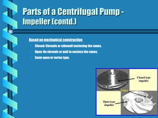
Based on mechanicalconstruction
• Closed: Shrouds or sidewall enclosing the vanes.
• Open: No shrouds or wall to enclose the vanes.
• Semi-open or vortex type.
Parts of a Centrifugal Pump -
Parts of a Centrifugal Pump -
Impeller (contd.)
Impeller (contd.)
51.
Closed impellers requirewear rings and these wear rings present another
maintenance problem.
Open and semi-open impellers are less likely to clog, but need manual
adjustment to the volute or back-plate to get the proper impeller setting and
prevent internal re-circulation.
Vortex pump impellers are great for solids and "stringy" materials but they
are up to 50% less efficient than conventional designs.
The number of impellers determines the number of stages of the pump. A
single stage pump has one impeller only and is best for low head service. A
two-stage pump has two impellers in series for medium head service. A multi-
stage pump has three or more impellers in series for high head service.
Parts of a Centrifugal Pump -
Parts of a Centrifugal Pump -
Impeller (contd.)
Impeller (contd.)
52.
Wear Rings
Wear ringprovides an easily and economically renewable
leakage joint between the impeller and the casing.
However, if the clearance between the impeller and the
casing becomes too large the pump efficiency will be
lowered causing heat and vibration problems. Most
manufacturers require that you disassemble the pump to
check the wear ring clearance and replace the rings when
this clearance doubles.
Parts of a Centrifugal Pump -
Parts of a Centrifugal Pump -
Wear Rings
Wear Rings
53.
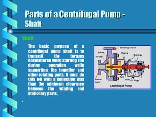
Shaft
The basic purposeof a
centrifugal pump shaft is to
transmit the torques
encountered when starting and
during operation while
supporting the impeller and
other rotating parts. It must do
this job with a deflection less
than the minimum clearance
between the rotating and
stationary parts.
.
Parts of a Centrifugal Pump -
Parts of a Centrifugal Pump -
Shaft
Shaft
54.
Parts of aCentrifugal Pump -
Parts of a Centrifugal Pump -
Shaft Sleeve
Shaft Sleeve
Pump shafts are usually protected from
erosion, corrosion, and wear at the seal
chambers, leakage joints, internal bearings,
and in the waterways by renewable sleeves.
Unless otherwise specified, a shaft sleeve of
wear, corrosion, and erosion-resistant
material shall be provided to protect the
shaft. The sleeve shall be sealed at one end.
The shaft sleeve assembly shall extend
beyond the outer face of the seal gland plate.
(Leakage between the shaft and the sleeve
should not be confused with leakage through
the mechanical seal).
Shaft Sleeve
55.
Couplings
Couplings can compensatefor axial growth of the shaft and transmit
torque to the impeller.
Shaft couplings can be broadly classified into two groups:
rigid and flexible.
Rigid couplings are used in applications where there is absolutely no
possibility or room for any misalignment.
Flexible shaft couplings are more prone to selection, installation and
maintenance errors. Flexible shaft couplings can be divided into two
basic groups: elastomeric and non-elastomeric.
Parts of a Centrifugal Pump -
Parts of a Centrifugal Pump -
Couplings
Couplings
56.
Elastomeric couplings useeither rubber or polymer elements to achieve flexibility.
These elements can either be in shear or in compression. Tire and rubber
sleeve designs are elastomer in shear couplings; jaw and pin and bushing
designs are elastomer in compression couplings.
Non-elastomeric couplings use metallic elements to obtain flexibility. These can
be one of two types:
lubricated or non-lubricated.
Lubricated designs accommodate misalignment by the sliding action of their
components, hence the need for lubrication.
The non-lubricated designs accommodate misalignment through flexing. Gear,
grid and chain couplings are examples of non-elastomeric, lubricated
couplings. Disc and diaphragm couplings are non-elastomeric and non-
lubricated.
Parts of a Centrifugal Pump -
Parts of a Centrifugal Pump -
Couplings (contd.)
Couplings (contd.)
57.
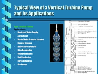
Type - VerticalTurbine
Applications :
• Municipal Water Supply
• Agricultural
• Waste Water Transfer Systems
• Booster Systems
• Hydrocarbon Transfer
• Mine Dewatering
• Offshore Platform
• Fish Hatcheries
• Barge Unloading
• Fire Pumps
Typical View of a Vertical Turbine Pump
Typical View of a Vertical Turbine Pump
and its Applications
and its Applications
58.
A centrifugal pumpis a simple
equipment that converts energy of a
prime mover (a electric motor or
turbine) first into velocity or kinetic
energy and then into pressure energy of
the fluid that is being pumped.
Centrifugal Pumps
Centrifugal Pumps
59.
Some of theCentrifugal Pumps & their
Some of the Centrifugal Pumps & their
Applications
Applications
End Suction Top Discharge Pumps
Applications
For continuous service in pumping
of clear water and turbid water up
to 300 ppm. These pumps are
ideally suitable for pumping water
in industries, sprinkler system,
booster services, fire fighting, air
conditioning, condensate water
supply etc.
60.
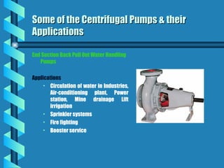
End Suction BackPull Out Water Handling
Pumps
Applications
• Circulation of water in Industries,
Air-conditioning plant, Power
station, Mine drainage Lift
irrigation
• Sprinkler systems
• Fire fighting
• Booster service
Some of the Centrifugal Pumps & their
Some of the Centrifugal Pumps & their
Applications
Applications
61.
Mixed Flow HighCapacity Low Head
Pumps
Applications
• Drainage water
• Storm water and supplying water
from settling tanks in water works
• Lift Irrigation
• Circulation of hot or cold water
• Air-conditioning plants
• Power stations
• Textile mills
• Tea Garden applications
Some of the Centrifugal Pumps & their
Some of the Centrifugal Pumps & their
Applications
Applications
62.
Double Stage HighHead Split Casing Pumps
Applications
• Water works
• Air-conditioning plants
• Power station
• Mine Drainage
• Lift irrigation
• Fire-fighting
• Paper and sugar mills
• Steel plants
Some of the Centrifugal Pumps & their
Some of the Centrifugal Pumps & their
Applications
Applications
63.
Horizontal Split CasingPumps
Applications
• Industries
• Water works
• Storm water
• Irrigation, sprinkler irrigation
• Water circulation
• Waste water treatment plants
• Air-conditioning plants
• Processing plants
• Refinery
• Cooling, auxiliary cooling
services in power plants
• Paper, sugar and textile mills etc.
Some of the Centrifugal Pumps & their
Some of the Centrifugal Pumps & their
Applications
Applications
64.
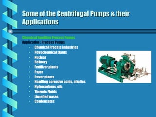
Chemical Handling ProcessPumps
Application : Process Pumps
• Chemical Process industries
• Petrochemical plants
• Nuclear
• Refinery
• Fertilizer plants
• Paper
• Power plants
• Handling corrosive acids, alkalies
• Hydrocarbons, oils
• Thermic Fluids
• Liquefied gases
• Condensates
Some of the Centrifugal Pumps & their
Some of the Centrifugal Pumps & their
Applications
Applications
65.
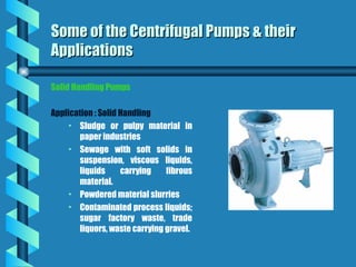
Solid Handling Pumps
Application: Solid Handling
• Sludge or pulpy material in
paper industries
• Sewage with soft solids in
suspension, viscous liquids,
liquids carrying fibrous
material.
• Powdered material slurries
• Contaminated process liquids;
sugar factory waste, trade
liquors, waste carrying gravel.
Some of the Centrifugal Pumps & their
Some of the Centrifugal Pumps & their
Applications
Applications
66.
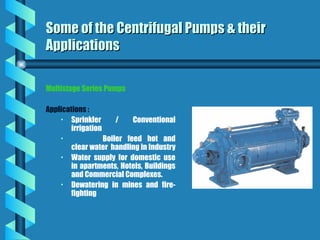
Multistage Series Pumps
Applications:
• Sprinkler / Conventional
irrigation
• Boiler feed hot and
clear water handling in Industry
• Water supply for domestic use
in apartments, Hotels, Buildings
and Commercial Complexes.
• Dewatering in mines and fire-
fighting
Some of the Centrifugal Pumps & their
Some of the Centrifugal Pumps & their
Applications
Applications
67.
Maintenance of CentrifugalPumps
Maintenance of Centrifugal Pumps
The operating manual of any centrifugal pump often starts with a
general statement,
“Your centrifugal pump will give you completely trouble free
and satisfactory service only on the condition that it is
installed and operated with due care and is properly
maintained.”
68.
Maintenance of CentrifugalPumps :
Maintenance of Centrifugal Pumps :
Reasons for Pump Failure
Reasons for Pump Failure
Despite all the care in operation and maintenance, engineers often face the
statement “the pump has failed i.e. it can no longer be kept in service”.
Inability to deliver the desired flow and head is just one of the most common conditions for
taking a pump out of service.
There are other many conditions in which a pump, despite suffering no loss in flow or head,
is considered to have failed and has to be pulled out of service as soon as possible. These
include :
• seal related problems ( leakage, loss of flushing, cooling, quenching systems, etc),
• pump and motor bearings related problems (loss of lubrication, cooling, contamination
of oil, abnormal noise, etc),
• leakage from pump casing,
• very high noise and vibration levels, or
• driver (motor or turbine) related problems.
69.
Maintenance of CentrifugalPumps
Maintenance of Centrifugal Pumps
The pump failure conditions mentioned earlier are neither exhaustive nor are the conditions
mutually exclusive. Often the root causes of failure are the same but the symptoms are different.
A little care when first symptoms of a problem appear can save the pumps from permanent
failures. Thus the most important task in such situations is to find out whether the pump has
failed mechanically or if there is some process deficiency, or both.
Many times when the pumps are sent to the workshop, the maintenance people do not find
anything wrong on disassembling it. Thus the decision to pull a pump out of service for
maintenance / repair should be made after a detailed analysis of the symptoms and root causes
of the pump failure.
Also, in case of any mechanical failure or physical damage of pump internals, the operating
engineer should be able to relate the failure to the process unit’s operating problems.
70.
Maintenance of CentrifugalPumps :
Maintenance of Centrifugal Pumps :
Reasons of Problems during Operation
Reasons of Problems during Operation
There are three types of problems mostly
encountered with centrifugal pumps :
· Design errors
· Poor operation
· Poor maintenance practices
71.
Maintenance of CentrifugalPumps :
Maintenance of Centrifugal Pumps :
Understanding the Equipment
Understanding the Equipment
Hence, the first step towards maintenance is
Hence, the first step towards maintenance is
proper understanding of the working
proper understanding of the working
principle of centrifugal pumps and
principle of centrifugal pumps and
identification of the major components of
identification of the major components of
such a pump.
such a pump.
72.
Centrifugal pumps arethe ultimate in simplicity. In general there are two basic
requirements that have to be met at all the times for a trouble free operation
and longer service life of centrifugal pumps.
The first requirement is that no cavitation of the pump occurs throughout the broad
operating range, and
The second requirement is that a certain minimum continuous flow is always
maintained during operation.
Further, pumping of neutral liquids at low temperature, absence of abrasive
materials in the liquid, continuous operation near maximum efficiency point,
use of proper material for different components, and adequate margin over
available NPSH over NPSH required (as stated in the manufacturer’s curve) may
considerably increase the life of a pump.
Maintaining & Operating Pumps -
Maintaining & Operating Pumps -
Tips & Tricks
Tips & Tricks
73.
The nature ofthe liquid to be pumped
For a given throughput, the viscosity largely determines the frictional losses and
hence the power required. The corrosive nature will determine the material
of construction both for the pump and the packing. With suspensions, the
clearance in the pump must be large compared with the size of the particles.
The nature of power supply
If the pump is to be driven by an electric motor or internal combustion engine, a
high-speed centrifugal or rotary pump will be preferred as it can be coupled
directly to the motor.
If the pump is used only intermittently, corrosion troubles are more likely than
with continuous working.
Maintaining & Operating Pumps -
Maintaining & Operating Pumps -
Tips & Tricks
Tips & Tricks
74.
Conclusions
Conclusions
Proper Maintenance ofPumps does not only start with repairs
and maintenance of worn parts but also comprises of :
• Proper selection : Operating demand to be placed upon the
equipment must be adequately anticipated over the projected life of
the equipment.
• Proper Installation : Neglect of fundamental precautions at the time
of installation may result in premature failure of the equipments.
• Operation of the equipment in a manner the equipment is designed
to be operated.
75.
Conclusions
Conclusions
Reliability and uninterruptedservice of pumps is vital to the
reliability and continued service of the entire plant.
Preventive maintenance is the most important aspect of any
maintenance plan. It should include :
• continuous performance monitoring,
• checking out of alignments, vibrations and noise levels from time
to time,
• following proper lubrication schedule,
• regular replacement of parts which have a known short life, and
• immediate repair or replacement of defective parts.
76.
Conclusions
Conclusions
Any operating /maintenance engineer, who desires to protect his
pumps from frequent failures must develop -
• a good understanding of the process,
• thorough knowledge of the mechanics of the pump,
• thorough knowledge of Material of Construction of different components,
and
• a good understanding of the preventive maintenance requirements from
time to time
Effective troubleshooting requires -
• an ability to observe changes in performance over time,
• and in the event of a failure, the capacity to thoroughly investigate the
cause of the failure and take measures to prevent the problem from re-
occurring.