Downloaded 3,285 times

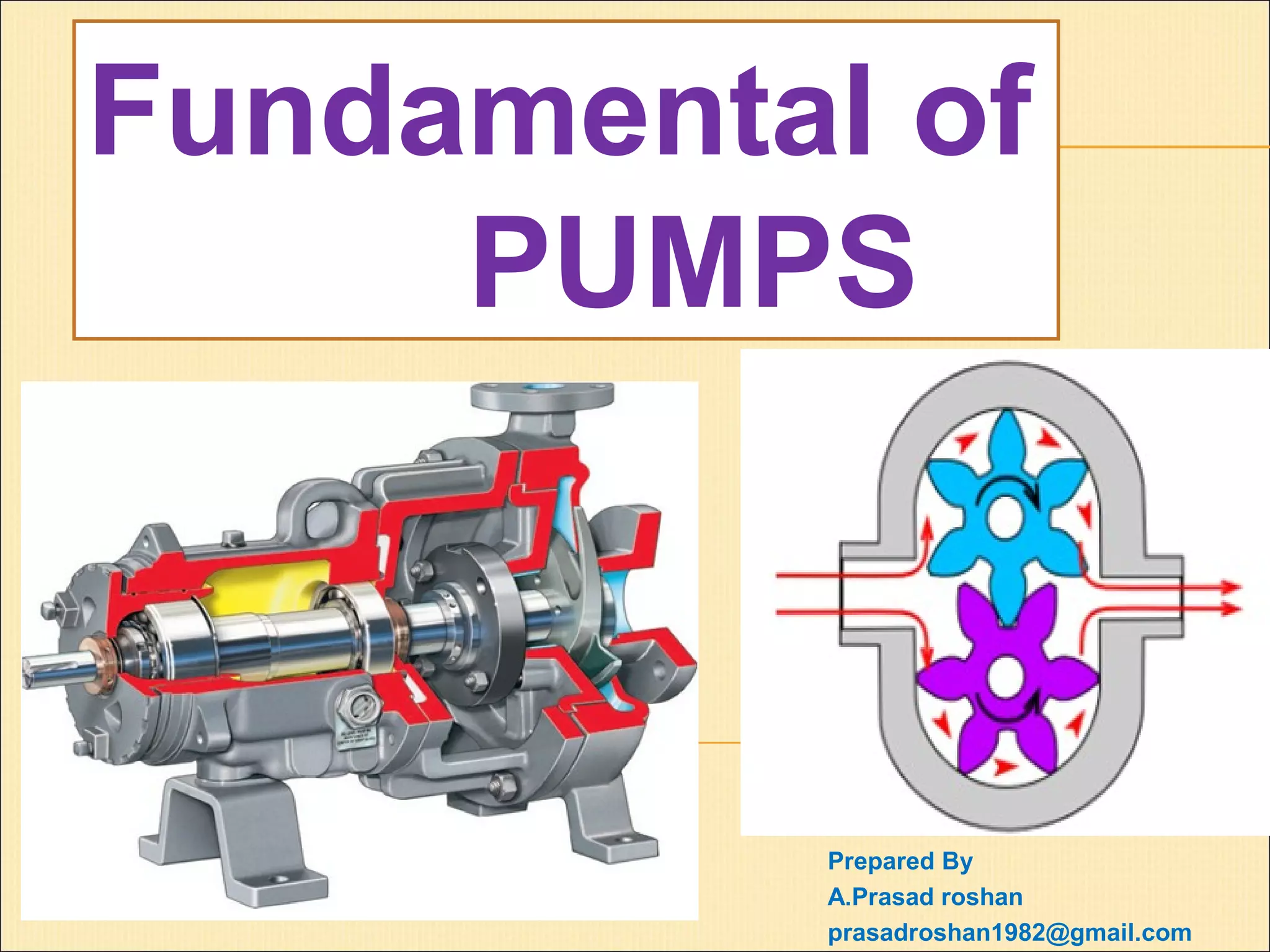
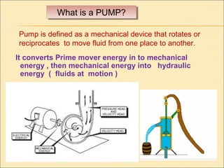
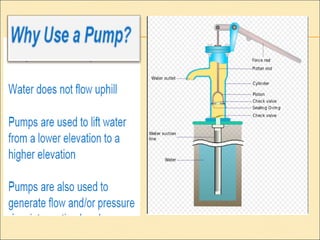
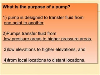
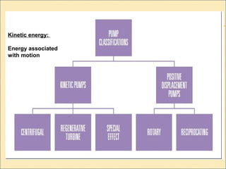
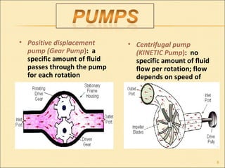
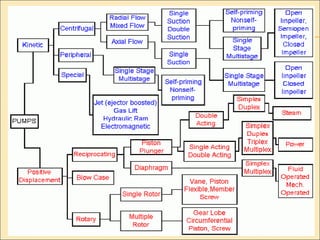
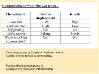
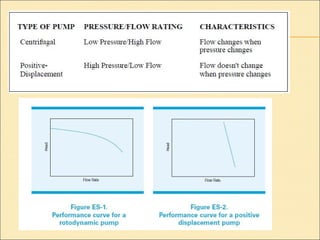
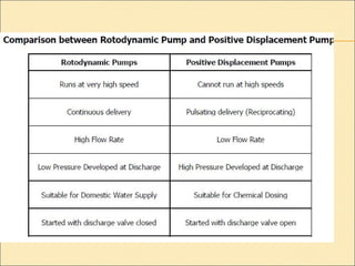
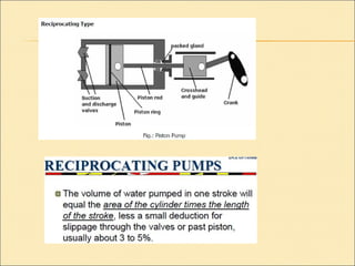
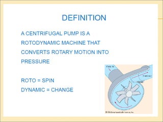
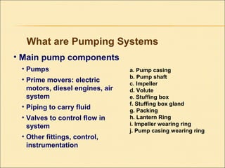
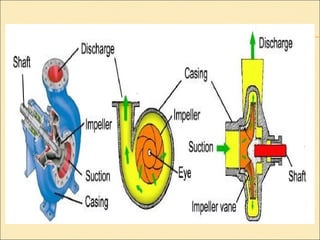
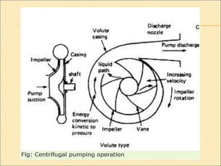
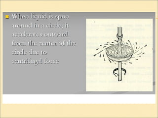
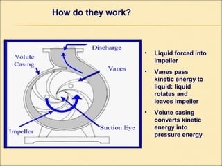
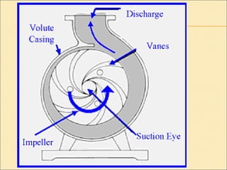
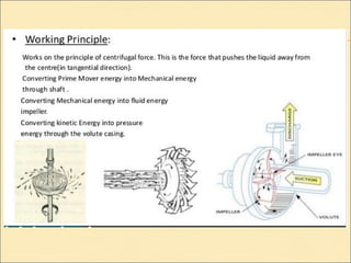
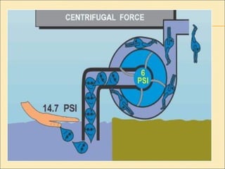
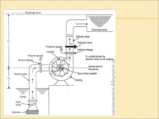
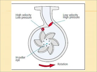
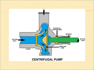
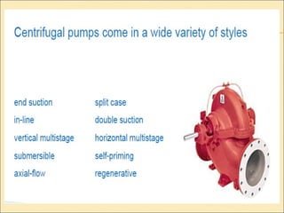
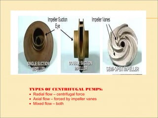
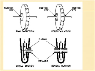
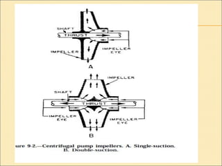
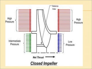
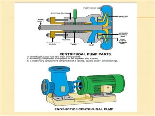


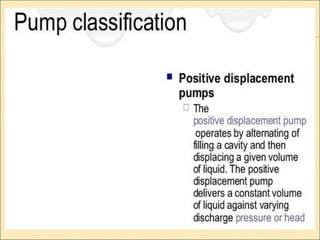
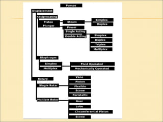
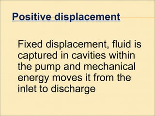
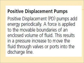
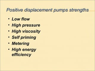

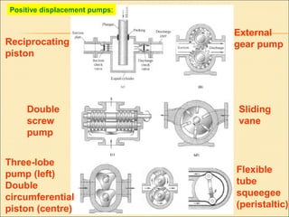
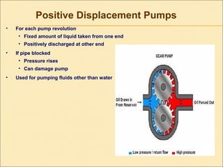
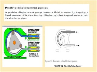
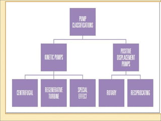


The document provides information about pumps, including: 1) Pumps are mechanical devices that use rotation or reciprocation to move fluid from one place to another by converting energy into hydraulic energy. 2) The main purposes of pumps are to transfer fluid from low to high pressure areas, from low to high elevations, and from local to distant locations. 3) There are two main types of pumps - positive displacement pumps which move a fixed volume of fluid with each cycle, and centrifugal pumps which use centrifugal force to move fluid by spinning an impeller.


