This document describes a simple method to program shape memory polymer sheets into different two-dimensional shapes using only scissors. The method involves cutting pre-strained polymer sheets into initial shapes and orientations, and then allowing the strain to relax through heating. The final shape is determined by the initial cut orientation relative to the strain direction. Identical initial rectangles cut at different angles take on different final shapes like squares or parallelograms as the strain relaxes. A geometric model is developed to predict the final shapes based on initial dimensions and orientation. Examples demonstrating re-keyable locks and high aspect ratio fibers are also presented.
![In-plane deformation of shape memory polymer sheets programmed
using only scissors
James R. Allensworth, Ying Liu, Hayley Braun, Jan Genzer*
, Michael D. Dickey*
Department of Chemical & Biomolecular Engineering, North Carolina State University, 911 Partners Way, Raleigh, NC 27695, USA
a r t i c l e i n f o
Article history:
Received 31 May 2014
Received in revised form
24 July 2014
Accepted 25 July 2014
Available online 6 August 2014
Keywords:
Shape morphing
Shape programming
Shape memory polymers
a b s t r a c t
This paper describes an unconventional, yet simple method to program sheets of shape memory polymer
into a variety of two dimensional (2D) structures. The final shape is “encoded” by physically cutting an
initial design out of a pre-strained film. The orientation of the initial cut-out relative to the direction of
strain and the subsequent relaxation of strain via heating defines the final shape. The appeal of the
approach described here is that an easy, low-cost cutting method can achieve a similar shape memory
effect attained by more complex processing techniques. Unlike conventional methods, where the final
shape of a shape memory polymer must be defined a priori, the direction of cutting of the polymer
defines its final shape without any complex pre-programmed strain profiles. A geometric model relating
the resolved 2D polymer shape to the initial shape and strain orientation reveals linear correlation be-
tween the model-predicted and experimentally-observed shapes. In addition to demonstrating the
principle with simple rectangular shapes, we suggest geometries related to encryption and high aspect
ratio fibers.
© 2014 Elsevier Ltd. All rights reserved.
1. Introduction
This paper describes a simple strategy to program polymer
sheets to shape-shift in-plane into a variety of structures in
response to heat. The process begins by cutting (e.g., using scissors)
a pre-strained, inexpensive, chemically-homogeneous, and
commercially available thin polymer sheet into an initial geometry.
Subsequent heating of the polymer above its glass transition allows
the strain to relax, which produces a final shape. The same initial
geometry can produce a variety of programmed shapes by rotating
the orientation of the initial cut-out relative to the strain direction.
This work represents an alternative way to program shape memory
polymers into a variety of geometrical two-dimensional (2D) forms
that may be difficult to fabricate using conventional approaches for
programming shape memory polymers.
Shape memory polymers adopt a pre-programmed shape in
response to an external stimulus, such as, heat, light, or electric
current [1e8]. Advances in shape memory polymers are motivated
by a wide range of applications including textiles [8], healthcare
[9,10], and actuators [2,11]. Fig. 1 illustrates the conventional
approach for programming shape memory polymers and contrasts
it with the alternative approach described here. In the conventional
approach, a polymer network starts in the desired state A, is
deformed while heating to a temporary state B, and is then cooled
to preserve the deformed state B [1,4]. Deformation of A into B
causes stress to build up in the polymer network, and cooling of B
locks-in the stress as a form of stored energy [4,12]. Upon heating
above a triggering temperature (e.g., above the glass transition
temperature), the polymer resorts to the initial state A as the
extended polymer chains relax [13,14].
As depicted in Fig. 1, our method eliminates the complex
deformation of the polymer from the desired state A to the
deformed state B, which requires careful control of stain profiles at
elevated temperatures, and instead defines the final shape B by
cutting shapes from a uniformly deformed polymer sheet. For a
given 2D initial shape, the orientation of the shape with respect to
the strain stored in the specimen dictates the final 2D shape of the
polymer. We note that although the polymer must be deformed in
both cases in Fig. 1, this alternative method achieves shape change
utilizing a uniform strain profile (black arrows in Fig. 1), which is
relatively easy to apply and is a common industrial process.
We demonstrated recently that it is possible to convert a single
shape memory polymer sheet into a wide range of three-
dimensional (3D) shapes by localizing external heating and there-
fore directing the location of relaxation to create a hinging response
* Corresponding authors.
E-mail addresses: Jan_Genzer@ncsu.edu (J. Genzer), mddickey@ncsu.edu
(M.D. Dickey).
Contents lists available at ScienceDirect
Polymer
journal homepage: www.elsevier.com/locate/polymer
http://dx.doi.org/10.1016/j.polymer.2014.07.042
0032-3861/© 2014 Elsevier Ltd. All rights reserved.
Polymer 55 (2014) 5948e5952](https://image.slidesharecdn.com/e37d3a63-3923-4134-84ed-91dcfb4fdd00-161106182721/85/pub-14-10-1-320.jpg)
![In-plane deformation of shape memory polymer sheets programmed
using only scissors
James R. Allensworth, Ying Liu, Hayley Braun, Jan Genzer*
, Michael D. Dickey*
Department of Chemical & Biomolecular Engineering, North Carolina State University, 911 Partners Way, Raleigh, NC 27695, USA
a r t i c l e i n f o
Article history:
Received 31 May 2014
Received in revised form
24 July 2014
Accepted 25 July 2014
Available online 6 August 2014
Keywords:
Shape morphing
Shape programming
Shape memory polymers
a b s t r a c t
This paper describes an unconventional, yet simple method to program sheets of shape memory polymer
into a variety of two dimensional (2D) structures. The final shape is “encoded” by physically cutting an
initial design out of a pre-strained film. The orientation of the initial cut-out relative to the direction of
strain and the subsequent relaxation of strain via heating defines the final shape. The appeal of the
approach described here is that an easy, low-cost cutting method can achieve a similar shape memory
effect attained by more complex processing techniques. Unlike conventional methods, where the final
shape of a shape memory polymer must be defined a priori, the direction of cutting of the polymer
defines its final shape without any complex pre-programmed strain profiles. A geometric model relating
the resolved 2D polymer shape to the initial shape and strain orientation reveals linear correlation be-
tween the model-predicted and experimentally-observed shapes. In addition to demonstrating the
principle with simple rectangular shapes, we suggest geometries related to encryption and high aspect
ratio fibers.
© 2014 Elsevier Ltd. All rights reserved.
1. Introduction
This paper describes a simple strategy to program polymer
sheets to shape-shift in-plane into a variety of structures in
response to heat. The process begins by cutting (e.g., using scissors)
a pre-strained, inexpensive, chemically-homogeneous, and
commercially available thin polymer sheet into an initial geometry.
Subsequent heating of the polymer above its glass transition allows
the strain to relax, which produces a final shape. The same initial
geometry can produce a variety of programmed shapes by rotating
the orientation of the initial cut-out relative to the strain direction.
This work represents an alternative way to program shape memory
polymers into a variety of geometrical two-dimensional (2D) forms
that may be difficult to fabricate using conventional approaches for
programming shape memory polymers.
Shape memory polymers adopt a pre-programmed shape in
response to an external stimulus, such as, heat, light, or electric
current [1e8]. Advances in shape memory polymers are motivated
by a wide range of applications including textiles [8], healthcare
[9,10], and actuators [2,11]. Fig. 1 illustrates the conventional
approach for programming shape memory polymers and contrasts
it with the alternative approach described here. In the conventional
approach, a polymer network starts in the desired state A, is
deformed while heating to a temporary state B, and is then cooled
to preserve the deformed state B [1,4]. Deformation of A into B
causes stress to build up in the polymer network, and cooling of B
locks-in the stress as a form of stored energy [4,12]. Upon heating
above a triggering temperature (e.g., above the glass transition
temperature), the polymer resorts to the initial state A as the
extended polymer chains relax [13,14].
As depicted in Fig. 1, our method eliminates the complex
deformation of the polymer from the desired state A to the
deformed state B, which requires careful control of stain profiles at
elevated temperatures, and instead defines the final shape B by
cutting shapes from a uniformly deformed polymer sheet. For a
given 2D initial shape, the orientation of the shape with respect to
the strain stored in the specimen dictates the final 2D shape of the
polymer. We note that although the polymer must be deformed in
both cases in Fig. 1, this alternative method achieves shape change
utilizing a uniform strain profile (black arrows in Fig. 1), which is
relatively easy to apply and is a common industrial process.
We demonstrated recently that it is possible to convert a single
shape memory polymer sheet into a wide range of three-
dimensional (3D) shapes by localizing external heating and there-
fore directing the location of relaxation to create a hinging response
* Corresponding authors.
E-mail addresses: Jan_Genzer@ncsu.edu (J. Genzer), mddickey@ncsu.edu
(M.D. Dickey).
Contents lists available at ScienceDirect
Polymer
journal homepage: www.elsevier.com/locate/polymer
http://dx.doi.org/10.1016/j.polymer.2014.07.042
0032-3861/© 2014 Elsevier Ltd. All rights reserved.
Polymer 55 (2014) 5948e5952](https://image.slidesharecdn.com/e37d3a63-3923-4134-84ed-91dcfb4fdd00-161106182721/75/pub-14-10-1-2048.jpg)
![[15]. The approach here has a similar appeal; it creates a variety of
in-plane (i.e., 2D shapes) from a single pre-strained polymer sheet
that may be fabricated in mass production at low cost. In-plane
shrinkage is useful for a number of applications including heat-
shrink packaging, unconventional fabrication of microfluidic
channels [16], and densification of lithographic features [17,18].
We demonstrate this alternative approach for shape program-
ming, characterize the geometric response, develop a predictive
model, and show a few illustrative examples of the method.
2. Discussion
We chose to use 0.05 mm thick Embrace films manufactured by
Eastman as model substrates because these uniaxially-strained
films are available commercially. These filmsdused industrially as
labels for plastic bottlesdshrink z50e60% in plane (along the di-
rection of strain) when heated above the glass transition temper-
ature (Tg). Polyester films similar to Embrace films quickly reach
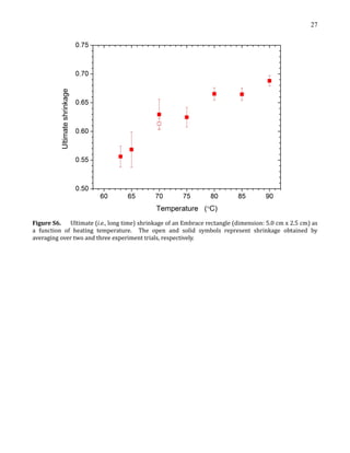
ultimate shrinkage without significant heating above Tg [19]. In
some of our experiments, we print patterns of ink on these films to
help visualize shape change and monitor the degree of shrinkage.
This principle is similar to patterns printed on industrially-
produced heat shrink polymer films. However, industrial applica-
tions scale the printed patterns before shrinking so that the final
image does not appear distorted after shrinking.
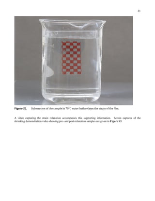
We used a hot water bath at 70 C to induce shrinkage in most of
the samples. We chose this temperature because it is above Tg,
produced significant shrinkage of the polymer sheet in less than a
minute, and provided a relatively safe working temperature (i.e., no
risk of boiling) with minimal evaporation of water. For convenience,
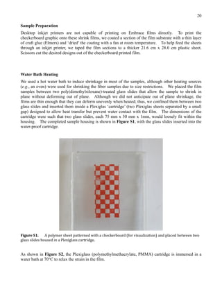
we placed the film samples in the gap of a ‘cartridge’ composed of
two glass slides in a Plexiglass holder (the completed sample
housing is shown in Figures S1 S2 in the Supporting Information)
and submerged it in the water bath. Although the cartridge is not a
necessity, it kept the samples dry during shrinkage. We removed
the samples from the water bath after being submerged for 45 s, at
which point the shrinkage appeared to halt.
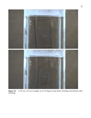
As a concept demonstrator, we cut identical rectangles
(2.5 cm  5 cm) from these films and oriented the cut-outs at an-
gles defined relative to the direction of strain. By arbitrary defini-
tion, an angle of zero degrees aligns the long axis of the rectangle
with the direction of strain. Fig. 2a illustrates the shape and
orientation of the samples, while Fig. 2b provides photographs of
the films before and after heating at 70 C. Black ink from a marker
added to the perimeter of the films after processing enhances
photographic contrast. The Supporting Information (Video S1 and
Figure S3) contains a video capturing the strain relaxation of a
rectangle cut from the film at 45.
Supplementary video related to this article can be found at
http://dx.doi.org/10.1016/j.polymer.2014.07.042.
It is possible to achieve a variety of final shapes from identical
starting patterns by varying only the orientation relative to the
Fig. 1. Comparison of approaches to program the final shape of shape memory polymers. The conventional approach requires managing complex strain profiles at elevated
temperatures, but the alternative approach described here uses only cutting at room temperature to define the final shape. The starting polymer sheet is commercially available and
produced by applying a uniform strain profile.
Fig. 2. (a) Identical rectangles (initial dimension: 2.5 cm  5 cm) cut from a uniaxially
strained film at varied angles relative to the direction of strain. (b) Upon heating above
the glass transition temperature, the identical rectangles (left) resolve into a variety of
final shapes (right). The number listed inside the rectangles refer to the angle of the
long axis of the rectangles relative to the direction of strain.
J.R. Allensworth et al. / Polymer 55 (2014) 5948e5952 5949](https://image.slidesharecdn.com/e37d3a63-3923-4134-84ed-91dcfb4fdd00-161106182721/85/pub-14-10-2-320.jpg)
![3. Summary
We demonstrate and model a new technique to program shape
memory polymers using only cutting to ‘program’ the final shape.
The appeal of this technique is that a single polymer shape cut from
a chemically homogeneous, commercial, pre-strained shape
memory polymer sheet can be converted into a variety of final 2D
shapes using only the orientation of cutting and relaxation of the
initial strain. We demonstrate an ‘encoded’ lock-and-key structure
in which both the lock and key change in sync depending on the
orientation. Upon heating, the three seemingly identical patterns
resolve into separate shapes, with each having a unique key. As
another demonstration, we fabricated high aspect ratio fibers by
cutting thin fibers at angles greater than 45 and heating above Tg.
Most shape memory polymers start from the desired final
shape, which is physically distorted into a temporary shape that
resorts back to the final shape upon heating. This physical distor-
tion requires careful control of complex strain profiles at elevated
temperatures. Here, we show the ability to define the final shape by
starting with a uniformly distorted sheet that is cut into a ‘pro-
grammed’ shape. This characteristic may be particularly useful for
applications involving shape memory polymers with shapes that
are difficult to pre-program or distort. Although shrink films have
been used in microfabrication and packaging, the work here is the
first to program the final shape by orienting and cutting the initial
geometry relative to the direction of uniaxial strain relaxation.
The approach here could, in principle, apply to any polymer that
can be pre-strained and cut. Although the polymer used here
cannot convert back to the original shape after shrinking, the
approach should apply to other versatile polymers such as cross-
linked, semicrystalline polymers or liquid crystal elastomers with
two-way shape memory effects that provide reversible actuation
[20,21]. Although the approach can produce a variety of shapes, it is
limited by the initial shapes that can be cut. Here, we used scissors,
but it should be possible to achieve more precise shapes by
employing a laser cutter, which has resolution closer to tens of
microns. We also limited ourselves to 2D shapes, but in principle,
the concept could be extended to 3D shapes with appropriate
cutting tools. An appeal of the 2D approach is it should be
compatible with in-plane processes such as lithography, roll-to-
roll, and inkjet printing although the necessity to cut the polymer
is inherently more wasteful than conventional approaches to shape
memory polymers. Ultimately, the shapes created by the technique
described here are limited by the complexity of the starting strain
profiles in the polymer (prior to cutting), but nevertheless, the
simplicity of the approach has appeal as an alternative method for
programming shape memory polymers.
Acknowledgments
We appreciate support from the National Science Foundation
(EFRI ODISSEI grant no. 1240438).
Appendix A. Supplementary data
Supplementary data related to this article can be found at http://
dx.doi.org/10.1016/j.polymer.2014.07.042.
References
[1] Lendlein A, Sauter T. Shape-memory effect in polymers. Macromol Chem Phys
2013;214:1175e7.
[2] Behl M, Razzaq MY, Lendlein A. Multifunctional shape-memory polymers. Adv
Mater 2010;22:3388e410.
[3] Ratna D, Karger-Kocsis J. Recent advances in shape memory polymers and
composites: a review. J Mater Sci 2008;43:254e69.
[4] Liu C, Qin H, Mather PT. Review of progress in shape-memory polymers.
J Mater Chem 2007;17:1543e58.
[5] Behl M, Zotzmann J, Lendlein A. Shape-memory polymers and shape-changing
polymers. In: Lendlein A, editor. Shape-memory polymers. Springer Berlin
Heidelberg; 2010. p. 1e40.
[6] Sun L, Huang WM, Ding Z, Zhao Y, Wang CC, Purnawali H, et al. Stimulus-
responsive shape memory materials: a review. Mater Des 2012;33:577e640.
[7] Leng J, Lan X, Liu Y, Du S. Shape-memory polymers and their composites:
stimulus methods and applications. Prog Mater Sci 2011;56:1077e135.
[8] Hu J, Zhu Y, Huang H, Lu J. Recent advances in shapeememory polymers:
structure, mechanism, functionality, modeling and applications. Prog Polym
Sci 2012;37:1720e63.
[9] Maitland DJ, Metzger MF, Schumann D, Lee A, Wilson TS. Photothermal
properties of shape memory polymer micro-actuators for treating stroke.
Lasers Surg Med 2002;30:1e11.
[10] Behl M, Lendlein A. Shape-memory polymers. Mater Today 2007;10:20e8.
Fig. 5. A photograph of a family of shape-shifting “locks and keys” created by heating
identical patterns cut at qI ¼ 0, 45, and 90 relative to the strain direction. The images
on the right show how the “lock” and “key” deform in sync from the same initial
geometries shown on the left. The red and blue ink is added for visualization purposes.
(For interpretation of the references to color in this figure legend, the reader is referred
to the web version of this article.)
Fig. 6. High aspect ratio polymer strands cut at qI ¼ 0 (red, left), 45 (black, middle),
and 90 (blue, right) relative to the strain direction. The aspect ratio (length/width)
changes can increase or decrease with heating depending on the orientation. (For
interpretation of the references to color in this figure legend, the reader is referred to
the web version of this article.)
J.R. Allensworth et al. / Polymer 55 (2014) 5948e5952 5951](https://image.slidesharecdn.com/e37d3a63-3923-4134-84ed-91dcfb4fdd00-161106182721/85/pub-14-10-4-320.jpg)
![[11] Behl M, Kratz K, Noechel U, Sauter T, Lendlein A. Temperature-memory
polymer actuators. Proc Natl Acad Sci U S A 2013;110:12555e9.
[12] Rousseau IA. Challenges of shape memory polymers: a review of the progress
toward overcoming SMP’s limitations. Polym Eng Sci 2008;48:2075e89.
[13] Pakula T, Trznadel M. Thermally stimulated shrinkage forces in oriented
polymers: 1. Temperature dependence. Polymer 1985;26:1011e8.
[14] Trznadel M, Pakula T, Kryszewski M. Thermally stimulated shrinkage forces in
oriented polymers: 2. Time dependence. Polymer 1985;26:1019e24.
[15] Liu Y, Boyles JK, Genzer J, Dickey MD. Self-folding of polymer sheets using
local light absorption. Soft Matter 2012;8:1764e9.
[16] Taylor D, Dyer D, Lew V, Khine M. Shrink film patterning by craft cutter:
complete plastic chips with high resolution/high-aspect ratio channel. Lab
Chip 2010;10:2472e5.
[17] Lee MH, Huntington MD, Zhou W, Yang J-C, Odom TW. Programmable soft
lithography: solvent-assisted nanoscale embossing. Nano Lett 2011;11:
311e5.
[18] Zhang B, Zhang M, Cui T. Low-cost shrink lithography with sub-22 nm reso-
lution. Appl Phys Lett 2012;100:133113.
[19] Shih WK. Shrinkage modeling of polyester shrink film. Polym Eng Sci
1994;34:1121e8.
[20] Meng H, Li G. Reversible switching transitions of stimuli-responsive shape
changing polymers. J Mater Chem 2013;1:7838.
[21] Chung T, Romo-Uribe A, Mather PT. Two-way reversible shape memory in a
semicrystalline network. Macromolecules 2008;41:184e92.
J.R. Allensworth et al. / Polymer 55 (2014) 5948e59525952](https://image.slidesharecdn.com/e37d3a63-3923-4134-84ed-91dcfb4fdd00-161106182721/85/pub-14-10-5-320.jpg)