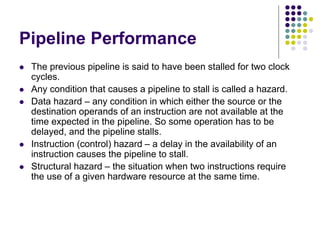
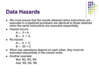
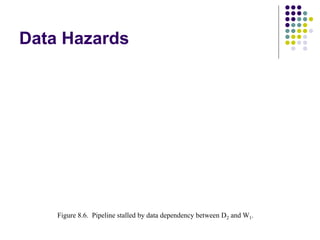
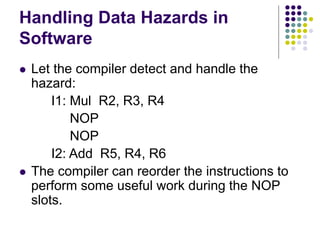
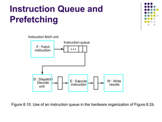
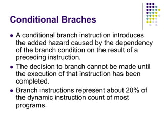
Pipeline Performance
F1
F2
F3
I1
I2
I3
E1
E2
E3
D1
D2
D3
W1
W2
W3
Instruction
F4 D4
I4
Clock c
y cle 1 2 3 4 5 6 7 8 9
Figure 8.3. Effect of an e
xecution operation taking more than one clock c
ycle.
E4
F5
I5 D5
Time
E5
W4
Pipeline Performance
 The previous pipeline is said to have been stalled for two clock
cycles.
 Any condition that causes a pipeline to stall is called a hazard.
 Data hazard – any condition in which either the source or the
destination operands of an instruction are not available at the
time expected in the pipeline. So some operation has to be
delayed, and the pipeline stalls.
 Instruction (control) hazard – a delay in the availability of an
instruction causes the pipeline to stall.
 Structural hazard – the situation when two instructions require
the use of a given hardware resource at the same time.
Pipeline Performance
F1
F2
F3
I1
I2
I3
D1
D2
D3
E1
E2
E3
W1
W2
W3
Instruction
Figure 8.4. Pipeline stall caused by a cache miss in F2.
1 2 3 4 5 6 7 8 9
Clock c
y cle
(a) Instruction execution steps in successiv e clock cy cles
1 2 3 4 5 6 7 8
Clock c
y cle
Stage
F: Fetch
D: Decode
E: Execute
W: Write
F1 F2 F3
D1 D2 D3
idle idle idle
E1 E2 E3
idle idle idle
W1 W2
idle idle idle
(b) Function perf ormed by each processor stage in successiv e clock cy cles
9
W3
F2 F2 F2
Time
Time
Idle periods –
stalls (bubbles)
Instruction
hazard
Pipeline Performance
F1
F2
F3
I1
I2 (Load)
I3
E1
M2
D1
D2
D3
W1
W2
Instruction
F4
I4
Clock c
y cle 1 2 3 4 5 6 7
Figure 8.5. Effect of a Load instruction on pipeline timing.
F5
I5 D5
Time
E2
E3 W3
E4
D4
Load X(R1), R2
Structural
hazard
Data Hazards
 We must ensure that the results obtained when instructions are
executed in a pipelined processor are identical to those obtained
when the same instructions are executed sequentially.
 Hazard occurs
A ← 3 + A
B ← 4 × A
 No hazard
A ← 5 × C
B ← 20 + C
 When two operations depend on each other, they must be
executed sequentially in the correct order.
 Another example:
Mul R2, R3, R4
Add R5, R4, R6
Data Hazards
F1
F2
F3
I1 (Mul)
I2 (Add)
I3
D1
D3
E1
E3
E2
W3
Instruction
Figure 8.6. Pipeline stalled by data dependenc
y between D
2 and W
1.
1 2 3 4 5 6 7 8 9
Clock c
y cle
W1
D2A W2
F4 D4 E4 W4
I4
D2
Time
Figure 8.6. Pipeline stalled by data dependency between D2 and W1.
Operand Forwarding
 Instead of from the register file, the second
instruction can get data directly from the
output of ALU after the previous instruction is
completed.
 A special arrangement needs to be made to
“forward” the output of ALU to the input of
ALU.
Handling Data Hazards in
Software
 Let the compiler detect and handle the
hazard:
I1: Mul R2, R3, R4
NOP
NOP
I2: Add R5, R4, R6
 The compiler can reorder the instructions to
perform some useful work during the NOP
slots.
Side Effects
 The previous example is explicit and easily detected.
 Sometimes an instruction changes the contents of a register
other than the one named as the destination.
 When a location other than one explicitly named in an instruction
as a destination operand is affected, the instruction is said to
have a side effect. (Example?)
 Example: conditional code flags:
Add R1, R3
AddWithCarry R2, R4
 Instructions designed for execution on pipelined hardware should
have few side effects.
Overview
 Whenever the stream of instructions supplied
by the instruction fetch unit is interrupted, the
pipeline stalls.
 Cache miss
 Branch
Unconditional Branches
F2
I2 (Branch)
I3
Ik
E2
F3
Fk Ek
Fk+1 Ek+1
Ik+1
Instruction
Figure 8.8. An idle c
ycle caused by a branch instruction.
Execution unit idle
1 2 3 4 5
Clock c
y cle
Time
F1
I1 E1
6
X
Branch Timing
Figure 8.9. Branch timing.
Fk+1 Dk+1
Ik+1 Ek+1
(b) Branch address computed in Decode stage
- Branch penalty
- Reducing the penalty
Instruction Queue and
Prefetching
F : Fetch
instruction
E : Execute
instruction
W : Write
results
D : Dispatch/
Decode
Instruction queue
Instruction fetch unit
Figure 8.10. Use of an instruction queue in the hardware organization of Figure 8.2b.
unit
Conditional Braches
 A conditional branch instruction introduces
the added hazard caused by the dependency
of the branch condition on the result of a
preceding instruction.
 The decision to branch cannot be made until
the execution of that instruction has been
completed.
 Branch instructions represent about 20% of
the dynamic instruction count of most
programs.

print.pptx

  • 1.
    Pipeline Performance F1 F2 F3 I1 I2 I3 E1 E2 E3 D1 D2 D3 W1 W2 W3 Instruction F4 D4 I4 Clockc y cle 1 2 3 4 5 6 7 8 9 Figure 8.3. Effect of an e xecution operation taking more than one clock c ycle. E4 F5 I5 D5 Time E5 W4
  • 2.
    Pipeline Performance  Theprevious pipeline is said to have been stalled for two clock cycles.  Any condition that causes a pipeline to stall is called a hazard.  Data hazard – any condition in which either the source or the destination operands of an instruction are not available at the time expected in the pipeline. So some operation has to be delayed, and the pipeline stalls.  Instruction (control) hazard – a delay in the availability of an instruction causes the pipeline to stall.  Structural hazard – the situation when two instructions require the use of a given hardware resource at the same time.
  • 3.
    Pipeline Performance F1 F2 F3 I1 I2 I3 D1 D2 D3 E1 E2 E3 W1 W2 W3 Instruction Figure 8.4.Pipeline stall caused by a cache miss in F2. 1 2 3 4 5 6 7 8 9 Clock c y cle (a) Instruction execution steps in successiv e clock cy cles 1 2 3 4 5 6 7 8 Clock c y cle Stage F: Fetch D: Decode E: Execute W: Write F1 F2 F3 D1 D2 D3 idle idle idle E1 E2 E3 idle idle idle W1 W2 idle idle idle (b) Function perf ormed by each processor stage in successiv e clock cy cles 9 W3 F2 F2 F2 Time Time Idle periods – stalls (bubbles) Instruction hazard
  • 4.
    Pipeline Performance F1 F2 F3 I1 I2 (Load) I3 E1 M2 D1 D2 D3 W1 W2 Instruction F4 I4 Clockc y cle 1 2 3 4 5 6 7 Figure 8.5. Effect of a Load instruction on pipeline timing. F5 I5 D5 Time E2 E3 W3 E4 D4 Load X(R1), R2 Structural hazard
  • 5.
    Data Hazards  Wemust ensure that the results obtained when instructions are executed in a pipelined processor are identical to those obtained when the same instructions are executed sequentially.  Hazard occurs A ← 3 + A B ← 4 × A  No hazard A ← 5 × C B ← 20 + C  When two operations depend on each other, they must be executed sequentially in the correct order.  Another example: Mul R2, R3, R4 Add R5, R4, R6
  • 6.
    Data Hazards F1 F2 F3 I1 (Mul) I2(Add) I3 D1 D3 E1 E3 E2 W3 Instruction Figure 8.6. Pipeline stalled by data dependenc y between D 2 and W 1. 1 2 3 4 5 6 7 8 9 Clock c y cle W1 D2A W2 F4 D4 E4 W4 I4 D2 Time Figure 8.6. Pipeline stalled by data dependency between D2 and W1.
  • 7.
    Operand Forwarding  Insteadof from the register file, the second instruction can get data directly from the output of ALU after the previous instruction is completed.  A special arrangement needs to be made to “forward” the output of ALU to the input of ALU.
  • 9.
    Handling Data Hazardsin Software  Let the compiler detect and handle the hazard: I1: Mul R2, R3, R4 NOP NOP I2: Add R5, R4, R6  The compiler can reorder the instructions to perform some useful work during the NOP slots.
  • 10.
    Side Effects  Theprevious example is explicit and easily detected.  Sometimes an instruction changes the contents of a register other than the one named as the destination.  When a location other than one explicitly named in an instruction as a destination operand is affected, the instruction is said to have a side effect. (Example?)  Example: conditional code flags: Add R1, R3 AddWithCarry R2, R4  Instructions designed for execution on pipelined hardware should have few side effects.
  • 11.
    Overview  Whenever thestream of instructions supplied by the instruction fetch unit is interrupted, the pipeline stalls.  Cache miss  Branch
  • 12.
    Unconditional Branches F2 I2 (Branch) I3 Ik E2 F3 FkEk Fk+1 Ek+1 Ik+1 Instruction Figure 8.8. An idle c ycle caused by a branch instruction. Execution unit idle 1 2 3 4 5 Clock c y cle Time F1 I1 E1 6 X
  • 13.
    Branch Timing Figure 8.9.Branch timing. Fk+1 Dk+1 Ik+1 Ek+1 (b) Branch address computed in Decode stage - Branch penalty - Reducing the penalty
  • 14.
    Instruction Queue and Prefetching F: Fetch instruction E : Execute instruction W : Write results D : Dispatch/ Decode Instruction queue Instruction fetch unit Figure 8.10. Use of an instruction queue in the hardware organization of Figure 8.2b. unit
  • 15.
    Conditional Braches  Aconditional branch instruction introduces the added hazard caused by the dependency of the branch condition on the result of a preceding instruction.  The decision to branch cannot be made until the execution of that instruction has been completed.  Branch instructions represent about 20% of the dynamic instruction count of most programs.