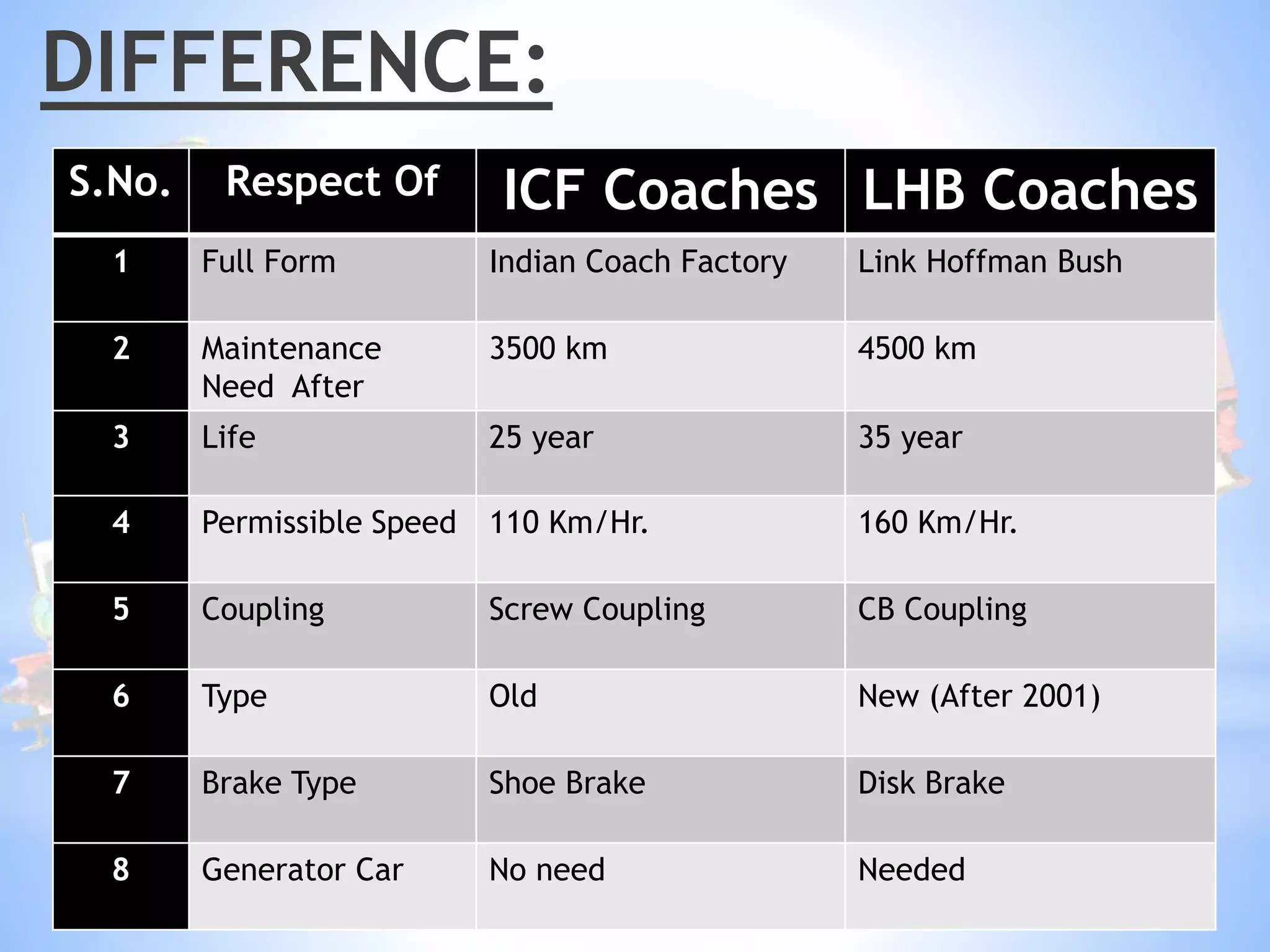
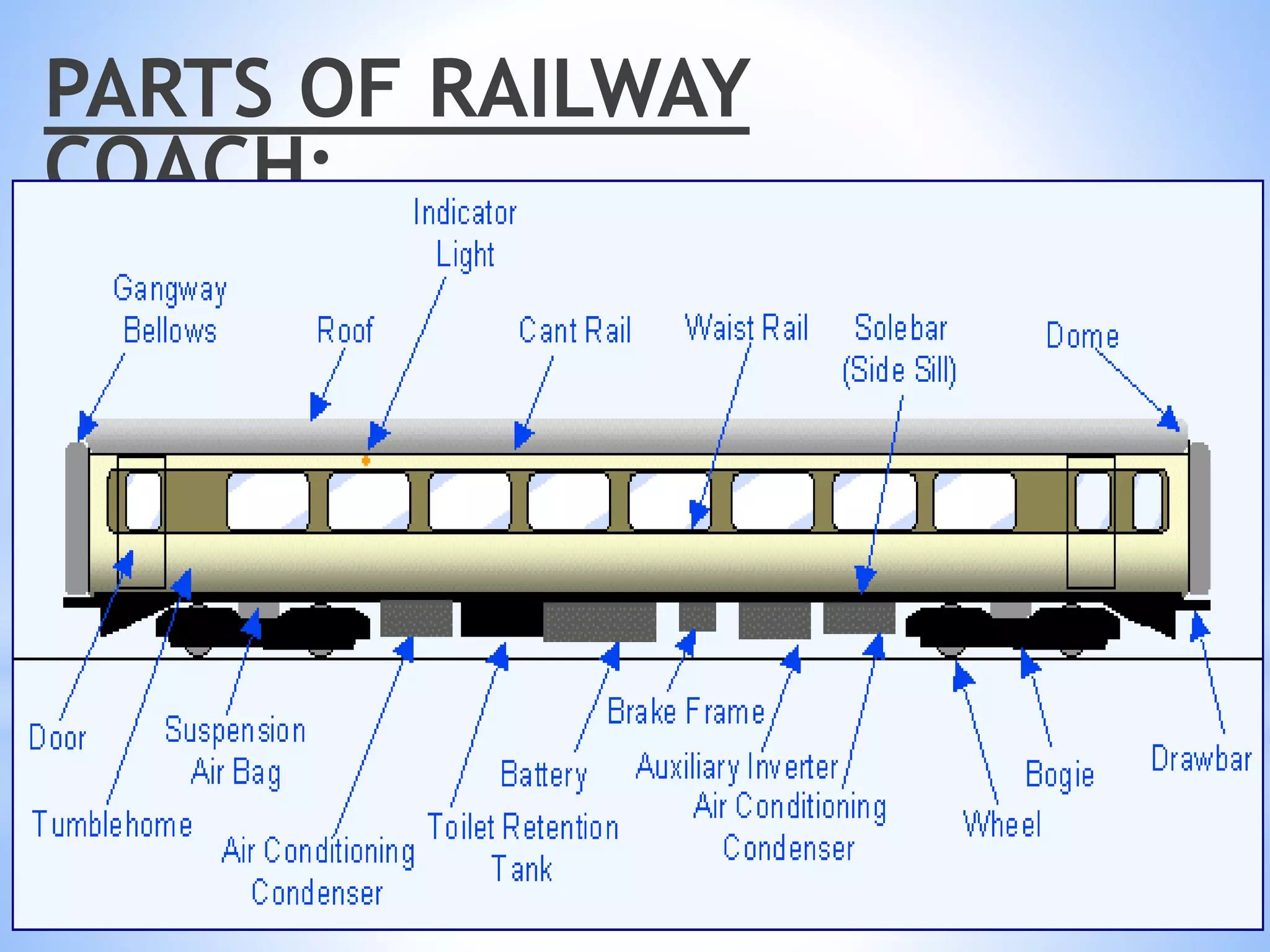
Department Of Mechanical Engineering
Seminar On Industrial training in
North Western Railway, Jaipur
Presented By:-
Ritik Baghmar
16EGJME102
7th Sem (B)
Presented To:-
Mr. Shabbir Aalam
CONTENT:
INTRODUCTION
HISTORY
RAILWAY COACHES
DIFFERENCE
TYPES OF RAILWAY COACHES
MAIN PARTS OF A RAILWAY COACH
BOGGIE
WHEEL
SUSPENSION SYSTEM
BRAKING SYSTEM IN RAILWAY BOGIE
C.D.T.S
MAINTENANCE
INTRODUCTION
*Indian railways is 4th largest railway network
having route length of 64,460 kms.
*Over 12,000 trains carries over 30 million
passengers and 2.8 millions tones of freight
daily.
*Word’s largest public sector enterprise with 1.5
million employees
HISTORY:
*The first railway proposals for India were made in
Madras in 1832
*By 1946 all 42 rails system taken over by govt. to make
a single nationalized network
*India's first passenger train, hauled by three steam
locomotives (Sahib, Sindh and Sultan), ran for 34
kilometres (21 mi) with 400 people in 14 carriages on
1,676 mm (5 ft 6 in) broad gauge track between
BoriBunder (Mumbai) and Thane on 16 April 1853
Types Of Coaches:
*ICF Coaches
*LHB Coaches
DIFFERENCE:
S.No. Respect Of ICF Coaches LHB Coaches
1 Full Form Indian Coach Factory Link Hoffman Bush
2 Maintenance
Need After
3500 km 4500 km
3 Life 25 year 35 year
4 Permissible Speed 110 Km/Hr. 160 Km/Hr.
5 Coupling Screw Coupling CB Coupling
6 Type Old New (After 2001)
7 Brake Type Shoe Brake Disk Brake
8 Generator Car No need Needed
PARTS OF RAILWAY
COACH:
SKECHAMATIC VIEW OF BOGGIE
PARTS OF BOGIE:
WHEEL:
There are mainly 2 types of
suspension for the trains.
Primary Suspension:
The primary suspension mainly
consists of normal spring damper
system which is used for structural
suspension of the train. They are
present in every bogie between the
axle box and the bogie.
Secondary Suspension:
This the airbag that is present
between the car and bogie frame as
shown in the figure above. This is a
primarily to aid comfort the
passengers travelling. Secondary
suspension is generally a pneumatic
suspension
SUSPENSION SYSTEM:
AIR BREAKING SYSTEM
Brakes applied with the help of air are called Air Brakes and the
system actuated to apply this phenomenon is known as Air
Brake System.
On the basis of type of release, air brake system is classified as:
*DIRECT RELEASE SYSTEM:-
Air released immediately in single pass, as soon as
releasing of brakes is initiated.
E.g.: freight trains
*GRADUATE RELEASE SYSTEM:-
Brake cylinder pressure can be reduced gradually in steps
in proportion to the increase in brake pipe pressure.
E.g.: passenger trains
MAIN COMPONENTS OF AIR BRAKE
1) Compressor:-Compresses the air it draws from atmosphere for the use in
AB and other pneumatic devices on train.
2) Main reservoir:-Store compressed air for braking and other pneumatic
applications.
3) Breaking pipe(BP) and Feed pipe(FP):-They run throughout the length of
the coach. They are coupled to one another by hose coupling to form a
continuous air supply from locomotive to the rear end of train.
4) Auxiliary Reservoir:-It is continuously charged through feed pipe. This
ensures full break force during emergency in case of leakage in break
cylinder.
5) Distributor:- A distributor is simply a sophisticated triple valve. It is
connected to Brake Pipe, Auxiliary Reservoir and Brake Cylinder
Working Of Air Brake
System:
When no brakes are applied, the Brake cylinder is
connected to atmosphere through a hole in
distributor valve. To apply brakes, the driver move the
handle. With this movement, the BP pressure is
reduced. This decrease in Pressure is sensed by the
distributor valve against the Control Reservoir
pressure. Air from the auxiliary reservoir enters the
break cylinder and the breaks are applied. The
diagram below shows the position of Break Cylinder,
Auxiliary Cylinder ,distributor (triple valve) in Brake
application.
Breaking
System:
BUFFER:
Buffers are the horizontal shock absorbing part with
coupling the adjacent coaches of the train so need regular
changing of shock absorbing rubber pads.
ALTERNATOR:
Alternator produces power while train was running .
Normally the power consumption of non AC Coach is
110V and for AC is 415V. In AC coach it use two face
alternator.
CONTROLLED DISCHARGE TOILET SYSTEM (CDTS):
*LHB coaches are fitted with controlled discharge toilet units to avoid soiling
of track in station. The toilet system is designed to operate with a
pressurized water bowl wash the covers 100% of the toilet bowl area. The
waste is removed from the toilet bowl and transferred to a retention tank
with a minimal amount of water.
*Water consumption is only 2.5 liters per flush cycle for the indian style toilet
bowl and 1.5 liters for the european style toilet bowl.
*This system works on electrical and pneumatic pressure arrangement.
*This system starts working on a single push of flush swith. As th flush switch
is pressed, water flows into the toilet bowl and the upper side valve opens
which is connected between the toilet bowl and retention tank. All the
toilet waste is transferred into the retention tank.
*The lower side valve of retention tank opens and the toilet waste
accumulated in the tank is discharged out of the tank to the rail side, away
from station and city.
TRAIN MAINTENANCE:
*Washing line :-
•After every 2500 km
*Sick line :-
•“A” maintenance- 1 month
•Schedule “B” maintenance- 3 months
•Intermideate Overhauling(IOH)- 9 months
or 2,00,000 km
• Periodic Overhaul(POH)- 18 months or
4,00,000 km
*Platform Train Duty:-
•On starting & ending stations
RAIL TRAVELLING CRANE:
*Have two crane hooks
*Main hook(35 ton capacity)
*Auxiliary hook(5 ton capacity
SICK LINE:
Sick line is the workshop for the major and periodical maintenance of
the coaches it consists of modern facilities like pit for working under
frame And crane for separation of coach & bogie for repair of all type of
defects like:-
*Repairing of damaged coaches.
*Maintenance of coaches.
*Heavy cranes used for lifting.
BREAK MAINTENANCE
*Changing of brake blocks.
*Adjustment of stroke length.
*Changing of brake cylinder.
*Leakages in breaking system.
BREAK TESTING:
Here S.C.T.R used for testing the brake and
it’s cylinder that acts as the main reservoir.
There are two pressure potentials i.e.
5kg/cm2 in brake pipe and 6kg/cm2 in feed
pipe
PRIMARY MAINTENANCE:
*Wheel profile.
*Oil in hydraulic dash pot.
*Axle box.
*Brakes blocks & piston stroke.
*Pest control treatment.
SECONDARY MAINTENANCE:
*Washing And Painting of coach body.
*Linen cleaning.
*Washing.
*Maintenance of A.C. equipment's.
*Clearing Blockage.
Presentation on Coach Care Complex

Presentation on Coach Care Complex

  • 1.
    Department Of MechanicalEngineering Seminar On Industrial training in North Western Railway, Jaipur Presented By:- Ritik Baghmar 16EGJME102 7th Sem (B) Presented To:- Mr. Shabbir Aalam
  • 2.
    CONTENT: INTRODUCTION HISTORY RAILWAY COACHES DIFFERENCE TYPES OFRAILWAY COACHES MAIN PARTS OF A RAILWAY COACH BOGGIE WHEEL SUSPENSION SYSTEM BRAKING SYSTEM IN RAILWAY BOGIE C.D.T.S MAINTENANCE
  • 3.
    INTRODUCTION *Indian railways is4th largest railway network having route length of 64,460 kms. *Over 12,000 trains carries over 30 million passengers and 2.8 millions tones of freight daily. *Word’s largest public sector enterprise with 1.5 million employees
  • 4.
    HISTORY: *The first railwayproposals for India were made in Madras in 1832 *By 1946 all 42 rails system taken over by govt. to make a single nationalized network *India's first passenger train, hauled by three steam locomotives (Sahib, Sindh and Sultan), ran for 34 kilometres (21 mi) with 400 people in 14 carriages on 1,676 mm (5 ft 6 in) broad gauge track between BoriBunder (Mumbai) and Thane on 16 April 1853
  • 6.
    Types Of Coaches: *ICFCoaches *LHB Coaches
  • 7.
    DIFFERENCE: S.No. Respect OfICF Coaches LHB Coaches 1 Full Form Indian Coach Factory Link Hoffman Bush 2 Maintenance Need After 3500 km 4500 km 3 Life 25 year 35 year 4 Permissible Speed 110 Km/Hr. 160 Km/Hr. 5 Coupling Screw Coupling CB Coupling 6 Type Old New (After 2001) 7 Brake Type Shoe Brake Disk Brake 8 Generator Car No need Needed
  • 8.
  • 9.
  • 10.
  • 11.
  • 12.
    There are mainly2 types of suspension for the trains. Primary Suspension: The primary suspension mainly consists of normal spring damper system which is used for structural suspension of the train. They are present in every bogie between the axle box and the bogie. Secondary Suspension: This the airbag that is present between the car and bogie frame as shown in the figure above. This is a primarily to aid comfort the passengers travelling. Secondary suspension is generally a pneumatic suspension SUSPENSION SYSTEM:
  • 13.
    AIR BREAKING SYSTEM Brakesapplied with the help of air are called Air Brakes and the system actuated to apply this phenomenon is known as Air Brake System. On the basis of type of release, air brake system is classified as: *DIRECT RELEASE SYSTEM:- Air released immediately in single pass, as soon as releasing of brakes is initiated. E.g.: freight trains *GRADUATE RELEASE SYSTEM:- Brake cylinder pressure can be reduced gradually in steps in proportion to the increase in brake pipe pressure. E.g.: passenger trains
  • 14.
    MAIN COMPONENTS OFAIR BRAKE 1) Compressor:-Compresses the air it draws from atmosphere for the use in AB and other pneumatic devices on train. 2) Main reservoir:-Store compressed air for braking and other pneumatic applications. 3) Breaking pipe(BP) and Feed pipe(FP):-They run throughout the length of the coach. They are coupled to one another by hose coupling to form a continuous air supply from locomotive to the rear end of train. 4) Auxiliary Reservoir:-It is continuously charged through feed pipe. This ensures full break force during emergency in case of leakage in break cylinder. 5) Distributor:- A distributor is simply a sophisticated triple valve. It is connected to Brake Pipe, Auxiliary Reservoir and Brake Cylinder
  • 15.
    Working Of AirBrake System: When no brakes are applied, the Brake cylinder is connected to atmosphere through a hole in distributor valve. To apply brakes, the driver move the handle. With this movement, the BP pressure is reduced. This decrease in Pressure is sensed by the distributor valve against the Control Reservoir pressure. Air from the auxiliary reservoir enters the break cylinder and the breaks are applied. The diagram below shows the position of Break Cylinder, Auxiliary Cylinder ,distributor (triple valve) in Brake application.
  • 16.
  • 17.
    BUFFER: Buffers are thehorizontal shock absorbing part with coupling the adjacent coaches of the train so need regular changing of shock absorbing rubber pads.
  • 18.
    ALTERNATOR: Alternator produces powerwhile train was running . Normally the power consumption of non AC Coach is 110V and for AC is 415V. In AC coach it use two face alternator.
  • 19.
    CONTROLLED DISCHARGE TOILETSYSTEM (CDTS): *LHB coaches are fitted with controlled discharge toilet units to avoid soiling of track in station. The toilet system is designed to operate with a pressurized water bowl wash the covers 100% of the toilet bowl area. The waste is removed from the toilet bowl and transferred to a retention tank with a minimal amount of water. *Water consumption is only 2.5 liters per flush cycle for the indian style toilet bowl and 1.5 liters for the european style toilet bowl. *This system works on electrical and pneumatic pressure arrangement. *This system starts working on a single push of flush swith. As th flush switch is pressed, water flows into the toilet bowl and the upper side valve opens which is connected between the toilet bowl and retention tank. All the toilet waste is transferred into the retention tank. *The lower side valve of retention tank opens and the toilet waste accumulated in the tank is discharged out of the tank to the rail side, away from station and city.
  • 20.
    TRAIN MAINTENANCE: *Washing line:- •After every 2500 km *Sick line :- •“A” maintenance- 1 month •Schedule “B” maintenance- 3 months •Intermideate Overhauling(IOH)- 9 months or 2,00,000 km • Periodic Overhaul(POH)- 18 months or 4,00,000 km *Platform Train Duty:- •On starting & ending stations
  • 21.
    RAIL TRAVELLING CRANE: *Havetwo crane hooks *Main hook(35 ton capacity) *Auxiliary hook(5 ton capacity SICK LINE: Sick line is the workshop for the major and periodical maintenance of the coaches it consists of modern facilities like pit for working under frame And crane for separation of coach & bogie for repair of all type of defects like:- *Repairing of damaged coaches. *Maintenance of coaches. *Heavy cranes used for lifting.
  • 22.
    BREAK MAINTENANCE *Changing ofbrake blocks. *Adjustment of stroke length. *Changing of brake cylinder. *Leakages in breaking system.
  • 23.
    BREAK TESTING: Here S.C.T.Rused for testing the brake and it’s cylinder that acts as the main reservoir. There are two pressure potentials i.e. 5kg/cm2 in brake pipe and 6kg/cm2 in feed pipe
  • 24.
    PRIMARY MAINTENANCE: *Wheel profile. *Oilin hydraulic dash pot. *Axle box. *Brakes blocks & piston stroke. *Pest control treatment.
  • 25.
    SECONDARY MAINTENANCE: *Washing AndPainting of coach body. *Linen cleaning. *Washing. *Maintenance of A.C. equipment's. *Clearing Blockage.