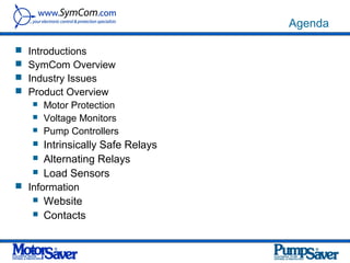
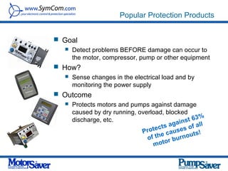
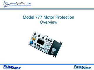
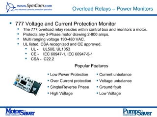
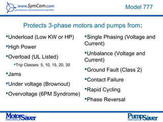
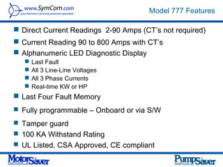
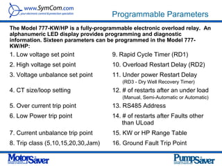
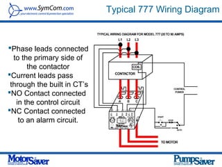
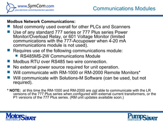
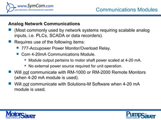
SymCom Product Overview


           Presented by:

           Steve Johnson
           Power Quality Asia inc.
Agenda

 Introductions
 SymCom Overview
 Industry Issues
 Product Overview
    Motor Protection
    Voltage Monitors
    Pump Controllers

    Intrinsically Safe Relays
    Alternating Relays
    Load Sensors
 Information
    Website
    Contacts
Company Overview

 SymCom was established in 1974 in Rapid City SD
 The company is a leading engineering and manufacturing firm that
  designs and develops:
    Electronic Control and Protection Products
    Custom and Private Labeled Products for Major OEMs
    The company’s focus is on five (5) main markets:
          Industrial Electrical
          Fresh Water Pumping
          Waste Water Pumping
          HVAC/R
          Custom OEM


           Designed, manufactured and tested in the USA
SymCom Brands

MotorSaver®                      PumpSaver®
 Motor Protection
                                  Alternating Relays
    Motor protection devices
    Communication modules
                                  Intrinsically-Safe Relays
    Remote monitoring devices    Pump Controllers
    Power Monitors               PumpSavers®
    Solutions software              3-phase PumpSavers®
 Voltage Monitors                   Single-phase PumpSavers®
    3-phase voltage monitors     Load Sensors
    Single-phase voltage         Auxiliary Products
     monitors                     Custom OEM Controls
 Current Monitors
    3-phase current monitors
    Single-phase current
     monitors
Popular Protection Products


 Goal
    Detect problems BEFORE damage can occur to
     the motor, compressor, pump or other equipment
 How?
      Sense changes in the electrical load and by
       monitoring the power supply
 Outcome
    Protects motors and pumps against damage
     caused by dry running, overload, blocked
                                                   %
     discharge, etc.                       n st 63
                                    ts agai of all
                             P rotec causes s!
                                    e          ut
                               of th r burno
                                  moto
Typical Applications

   Air handlers
   Conveyor drive
   Oil and gas pumps
   Elevator drives
   Irrigation pumps
   Power substation monitoring
   Lift station pumps
   Water waste and sewage machinery
   Robotics equipment
   Computer power protection
   Sawmill and wood pump machinery
   Automatic transfer switching for emergency power supplies
   Commercial/Industrial air conditioning and refrigeration
    compressors
Industry Issues


 Voltage
      Low Voltage
           A long reduction in voltage, for example, the heavy
            usage of air conditioning during summer could lead
            to low voltage or brownouts and cause
                Equipment shutdowns
                Reduced motor torque, increased stalling
                Overheating of motors (insulation breakdown)
                Tripping of protective devices
      High Voltage
           Electronic and electrical devices are designed to
            operate at a certain maximum supply voltage
           Considerable damage can be caused by voltage that
            is higher than that for which the devices are rated
Industry Issues

• Phase Loss / Phase Reversal
   •   Can occur from lightening, down power lines, blown
       fuse, wiring error or contactor failure
   •   This causes motor windings to over heat and
       prevents the motor from operating at its rated horse
       power
Industry Issues


  Voltage Imbalance               • Voltage Unbalance
                                     • Voltage unbalance - a voltage unbalance
                                       between the three phases. Possible causes,
                                        •   Lines are lost
                                        •   A tin can transformer is replaced by another
                                            model
                                        •   A contactor becomes worn
A power outage, caused by
high winds, affected 150,000
                                        •   A new load is added to one phase of a facility’s
customers in eight counties                 power system
north and east of Houston. A
spokesman with Entergy Texas
said 16 transmission lines were
                                     • A slight voltage unbalance causes a significant
lost, which caused a voltage           temperature increase and causes premature
unbalance and led to the
emergency shutdown of a                failure
power plant in Willis, about 45
miles north of Houston.
Protecting These Industries

 Air Conditioning Industry
                                     Industrial Pumping Industry
 • Air handling units
                                     • Water and petroleum
 •   Rooftop systems
 •   Screw compressors                 pumping markets
 •   Scroll compressors
 •   Heat pumps                                Fire pump Control Industry
 •   Chillers                                  • Specialty products used in
 •   Self-contained A/C systems                 fire pump control panels

Mining Industry
                                    Submersible Pumping Industry
Pump protection, ground fault
and monitoring on motors for        • Water pumping markets
protection of
• Crushers*                                  Refrigeration Industry
• Conveyors
                                             • Devices work with existing
• Pulverizers*
• Pelletizers                                 systems to perform critical
*contact factory for applications             operational functions
Model 777 Motor Protection
        Overview
Overload Relays – Power Monitors

 777 Voltage and Current Protection Monitor
      The 777 overload relay resides within control box and monitors a motor.
      Protects any 3-Phase motor drawing 2-800 amps.
      Multi ranging voltage 190-480 VAC.
      UL listed, CSA recognized and CE approved,
         UL - UL508, UL1053
         CE - IEC 60947-1, IEC 60947-5-1
         CSA - C22.2
                                     Popular Features
                     Low Power Protection       Current unbalance
                     Over Current protection    Voltage unbalance
                     Single/Reverse Phase       Ground fault
                     High Voltage               Low Voltage
Model 777


        Protects 3-phase motors and pumps from:
Underload (Low KW or HP)             Single Phasing (Voltage and
                                      Current)
High Power
                                      Unbalance (Voltage and
Overload (UL Listed)
                                      Current)
   Trip Classes: 5, 10, 15, 20, 30
                                      Ground Fault (Class 2)
Jams
                                      Contact Failure
Under voltage (Brownout)
                                      Rapid Cycling
Overvoltage (6PM Syndrome)
                                      Phase Reversal
Model 777 Features

 Direct Current Readings 2-90 Amps (CT’s not required)
 Current Reading 90 to 800 Amps with CT’s
 Alphanumeric LED Diagnostic Display
      Last Fault
      All 3 Line-Line Voltages
      All 3 Phase Currents
      Real-time KW or HP
 Last Four Fault Memory
 Fully programmable – Onboard or via S/W

 Tamper guard
 100 KA Withstand Rating
 UL Listed, CSA Approved, CE compliant
Model 777 Additional Features

 Automatic, Semi- Automatic or Manual Reset
      # of Restarts After Under load (Manual, 1, 2, 3, 4, Always)
      # of Restarts After Faults (Manual, 1, 2, 3, 4, Always)
 Automatic Dry Well Recovery Calculator (Auto Compensates
  for “Dry” vs. “Wet” Periods)

 RS485 communications port (ModBus/DeviceNet/ProfiBus/ENet)


 View Data from Remote Monitor (RM1000 or RM2000 or PC)

 Addressable – Up to 99 Units per Network
 Protocol Manual Available (Interface to PLC, SCADA, DCS, PC)
 5 Year Warranty
 Made in USA
Model 777 Benefits
 Extends motors and pump life by offering superior
    motor protection.
   Helps with troubleshooting adverse conditions without
    having to change out a damaged motor or pump.
   Reduces arc flash hazards when remote monitors are
    used.
   Allows the user to monitor, diagnose, and control
    motors remotely.
   Reduce warranty replacement costs
   Economical motor and pump protection
   Saves time troubleshooting motor and pump
    problems.
777 KW/HP


Power Monitor   Overload Relay
Programming the 777

The 777 can be programmed from:
   a. The front of the 777
   b. A remote computer
   c. A remote display

1.   Rotate the MODE SELECT switch to the parameter to
     be programmed
2.   Depress and hold the RESET/PROGRAM button
3.   Rotate the DISPLAY/PROGRAM screw to the desired
     setting as shown in the LED display and
4.   Release the RESET/PROGRAM button
Unit can be locked-out to prevent unauthorized tampering of set-points
Programmable Parameters
The Model 777-KW/HP is a fully-programmable electronic overload relay. An
alphanumeric LED display provides programming and diagnostic
information. Sixteen parameters can be programmed in the Model 777-
KW/HP:
1. Low voltage set point             9. Rapid Cycle Timer (RD1)
2. High voltage set point            10. Overload Restart Delay (RD2)
3. Voltage unbalance set point       11. Under power Restart Delay
                                         (RD3 - Dry Well Recovery Timer)
4. CT size/loop setting              12. # of restarts after an under load
                                         (Manual, Semi-Automatic or Automatic)
5. Over current trip point           13. RS485 Address
6. Low Power trip point              14. # of restarts after Faults other
                                         than ULoad
7. Current unbalance trip point      15. KW or HP Range Table
8. Trip class (5,10,15,20,30,Jam)    16. Ground Fault Trip Point
Typical 777 Wiring Diagram


Phase leads connected
  to the primary side of
       the contactor
Current leads pass
 through the built in CT’s
NO Contact connected
   in the control circuit
NC Contact connected
    to an alarm circuit.
Communications Modules

Modbus Network Communications:
 Most commonly used overall for other PLCs and Scanners
 Use of any standard 777 series or 777 Plus series Power
    Monitor/Overload Relay, or 601 Voltage Monitor (limited
    communications with the 777-Accupower when 4-20 mA
    communications module is not used).
   Requires use of the following communications module:
      RS485MS-2W Communications Module
   Modbus RTU over RS485 two wire connection.
   No external power source required for unit operation.
   Will communicate with RM-1000 or RM-2000 Remote Monitors*
   Will communicate with Solutions-M Software (can be used, but not
    required).
* NOTE: at this time the RM-1000 and RM-2000 are not able to communicate with the LR
   versions of the 777 Plus series when configured with external current transformers, or the
   P1 versions of the 777 Plus series. (RM unit updates available soon.)
Communications Modules

Ethernet Communications Module
 Compatible (plug and play) with the 777 Plus Series.
 User configurable to work with the standard 777 series and the
  601.
 Requires use of the following items:
    777 Plus series Power Monitor/Overload Relay.
    CIO-EN Communications Module.
           24VDC source required for unit operation.
   Modbus RTU over RS485 two wire connection.
   Modbus TCP over Ethernet cable.
   Will communicate with RM-1000 or RM-2000 Remote Monitors*
   Will communicate with Solutions-M Software (can be used, but not
    required).
* NOTE: at this time the RM-1000 and RM-2000 are not able to
   communicate with the LR versions of the 777 Plus series when
   configured with external current transformers, or the P1 versions of the
   777 Plus series. (RM unit updates available soon.)
Communications Modules


DeviceNet Network Communications
 (Most commonly used by Allen Bradley / Rockwell
  Automation PLCs and Scanners).
 Requires use of the following items:
      777 Plus series Power Monitor/Overload Relay.
      CIO-DN-P Communications Module (for 24V dry contact
       inputs), or CIO-120-DN-P Communications Module (for
       120VAC inputs). 24VDC source required for unit operation.
 Will not communicate with RM-1000 or RM-2000
  Remote Monitors.
 Will communicate with Solutions-D Software (can be
  used, but not required).
Communications Modules

Profibus Network Communications
 (Most commonly used by Siemens PLCs and
  Scanners).
 Requires use of the following items:
      777 Plus series Power Monitor/Overload Relay.
      CIO-777-PR Communications Module.
           24VDC source required for unit operation.
 Will not communicate with RM-1000 or RM-2000
  Remote Monitors.
 Will not communicate with Solutions Software.
Communications Modules


CIO-MB (for 24V dry contact inputs) / CIO-120-MB (for
  120VAC inputs)
      Compatible (plug and play) with the 777 Plus series
      User configurable to work with the standard 777 series and
       the 601.
      Modbus RTU over RS485 two wire connection.
      24VDC source required for unit operation.
Communications Modules

Analog Network Communications
 (Most commonly used by network systems requiring scalable analog
  inputs, i.e. PLCs, SCADA or data recorders).
 Requires use of the following items:
    777-Accupower Power Monitor/Overload Relay.
    Com 4-20mA Communications Module.
          Module output pertains to motor shaft power scaled at 4-20 mA.
          No external power source required for unit operation.
 Will not communicate with RM-1000 or RM-2000 Remote Monitors
  (when 4-20 mA module is used).
 Will not communicate with Solutions-M Software when 4-20 mA
  module is used.
777 Coupled With Remote Monitor

 777 coupled with Remote Monitor
      An RM2000 remote monitor mounted on the control box door displays
       critical information and allows changes to set points on the 777 without
       having to expose one to the hazards of arc flash.
      The RM2000-RTDW will accept up to 8 RTD inputs.
      The RM1000 could monitor up to 16 units.
Model RM-2000
Remote Displays RM2000/RM1000


 Monitors vital motor parameters
    Voltage, Current, Unbalance, Power, Ground
     current
    Limits exposure to ARC Flash Hazards by having
     information displayed on outside of MCC cabinet.
 Displays last 4 motor fault information
    (RM 2000 records voltages and currents values at
     time of fault)
 Program the 777 remotely
 Allows for remote reset
RM-2000 Features


 Liquid crystal display
 LED’s indicate mode of operation, fault status,
    communication status and run status
   Easily mounted on the front of a panel and rated for
    environmental protection (NEMA 3R)
   Stores motor history information with date and time stamp
   Can be mounted up to 4000 ft. from the motor starter
   Second communication port is standard
Key Features - Benefits


1. REAL-TIME 3 LINES VOLTGAGE AND CURRENT
        •    This is a real time screen to read if one line is out of balance.


2. REAL-TIME 3 CURRENT LEVELS
        •    Currents on lines 1, 2 & 3 with average between the three lines
             displayed.
3. REAL-TIME 3 VOLTGAGE LEVELS
        •    Incoming voltage levels on Lines 1-2, 2-3 and 3-1 with average
             between the three lines displayed.

4.CURRENT & VOLTGAGE UNBALANCE
        •    Indicates the unbalance percentage of the current the motor is running
             at and the incoming line voltage.
5. RESTART DELAY TIMERS
    •       This display shows the time left to reset, if the 777 has tripped on a fault


6. GROUND FAULT CURRENT AMPS
        •    Displays the amount of ground fault, in amps. This helps guard
             against ground faults that could lead to premature motor failure
             overtime.
Key Features - Benefits

7. ACCUMLATIVE HOURS AND ENERGY
     •   This displays the accumulative hours of operation (when the motor is
          running) and the energy used in KW hours. This screen feature helps
          one to schedule maintenance for the motor and/or driven equipment.

8. # OF FAULTS AND # OF TRIPS
     •   This display feature shows the number of actual starts the motor has
         had and the number of times the unit tripped on a current fault.


9. VOLTAGE, CURRENT, POWER FACTOR
     •   This screen shows the average of the voltage and current and power
         factor.


10.POWER CONSUMTION
     •   The actual power consumption is displayed as well as the KVARS.


11. PENDING FAULT
      • This screen will ‘pop up’ and display at anytime when a pending fault
        problem may be occurring. The unit displays multiple fault indications
        such as Voltage and Current unbalance, etc. and captures relevant
        data like date and time.
Key Features - Benefits

12. FAULT 2
      • This shows the Current Unbalance when a fault occurs along with the
        day and time the fault occurred.


13. FAULT 2 was a CURRENT UNBALANCE
      • This display indicates the current levels at the time of the fault. If we
        did the math, we would see that the unbalance was at 23%. We had
        our CUB set at 10% and #RF at 0. We determined that we had a faulty
        contactor, thus we stopped a current single phase from burning up the
        motor.

 14. FAULT 2
       • This screen shows that at the time of the fault, we had .09A of ground
         fault current, which will happen when you have a current unbalance.

 15. FAULT 2
      •   This screen shows that the voltages at the time of the fault were
          balanced, so the fault was on the load side of the contactor.

  16. FAULT 2
       •   This screen displays the voltage unbalance (0%) and the average
           voltage for the unit.

  17. FAULT 2
       •   This screen displays the current unbalance (0%) and the average
           current for the unit.
RM 1000 Remote Display
RM 1000 Features


 Monitors up to 16 Model 777 devices
 Easily mounted on the front of a panel
 Displays current and voltages
 Displays fault condition
 Remote reset of MotorSaver/PumpSaver
 Standard communication port
 Displays run hours on each motor
777-KW/HP Competitive Advantages

   Under-Power Tripping – Being able to trip on under-power instead of
    under-current means a more accurate and faster trip – meaning better
    protection to the motor. This is particularly advantageous to pumps
    where their running dry can cause pump damage. Most of our
    competition trips on under-current only, or does not offer under-current
    tripping at all.
   Advanced Motor Protection Affordably – This unit provides motor
    protection from the primary causes of damage due to electrical issues.
    These include voltage, phase, current and ground fault monitoring. In
    addition it provides a display for monitoring voltage & current and
    communications to monitoring systems. Most of our competition offering
    these protection features are at MUCH higher price points (often 3 to 5
    times our price or more).
   Multiple Communication Options – When the user wants to monitor their
    motors/pumps via SCADA or other software, this unit provides multiple
    protocols to make integration easy. These include Modbus RTU,
    Profibus, DeviceNet, and Ethernet Modbus TCP. Most of our competition
    offers no communications or perhaps only 1 or 2 of these options.
   Networking: Up to 99 units can be networked together and 16 units can
    be on a sub-network via one remote monitor.
Voltage Monitor Overview
460 3-Phase Monitor


Surface or DIN rail
mount three phase           Four adjustment pots
voltage monitor with        Voltage Adjustment
self-adjustments.           Restart in seconds
                            Adjustable Trip delay
   Loss of any phase       Voltage Unbalance Delay
   Low and High voltage    LEDs indicate trip status
   Voltage unbalance        and make trouble
   Phase reversal           shooting a snap.
   Rapid cycling           Microcontroller based
   Adjustable Trip and      circuitry provides better
    Restart delay            accuracy and higher
                             reliability than analog
                             designs.
460 Phase Wiring Diagram
201A-AU 3-Phase Voltage Monitor

8 pin plug-in Octal Phase Monitor for 3-
Phase Motor protection
    Loss of any phase
    Low voltage
    High voltage
    Voltage unbalance
    Phase reversal
    Rapid cycling
    Adjustable Trip and Restart delay
    UL508 and IEC 60947-6-2


                            Bi-colored LED Indicator
201A-AU Wiring Diagram
201A-AU 3-Phase Voltage Monitor


Universal voltage adjustment
       190-480 VAC – 50/60 Hz

Adjustment knobs allow the user to set
       1-30 sec trip delay
       1-500 second restart delay
       2-8% voltage unbalance trip point

Bi-colored LED indicates trip status
                                            Protecting an Elevator within
                                               the Control Box
                                                  This microcontroller-based
                                                   voltage and phase-sensing
                                                   device constantly monitors
                                                   the 3-phase voltages to
                                                   detect harmful power line
                                                   conditions.
460 & 201A-AU Advantages

 Universal Voltage – Being able to set our unit to work on voltages from
  190-480V means that the user only needs to worry about 1 unit type for
  replacement purposes on both 230V and 460/480V applications, the local
  distributor only needs to keep 1 on the shelf, the service techs only need
  to have 1 unit type on their truck, etc. Most of our competition requires
  two separate units for these different voltage ranges.
 Diagnostic LED – instead of just telling the user that the unit has tripped,
  we help the user determine the cause of trip so that they can solve the
  problem. Most of our competition only tells you that the unit has tripped,
  but not why.
 More User Adjustability – Different applications and installation sites can
  have unique issues. Being able to adjust the trip delay, restart delay and
  trip set point for the voltage unbalance means the end user can set these
  for that location’s unique needs. Most of our competition has fixed set
  points for these things.
 No line-side fuses required – Our units are UL approved without the
  requirement for line-side fuses to protect our unit. Most of our
  competition require these fuses, which adds further cost to the project.
201 New Products
Model 201-XXX-DPDT
Features:
 Low voltage protection
   Single-phase protection
   Reverse-phase protection
   Voltage unbalance protection
   Two isolated Form C relays (DPDT)
   Diagnostic LED
   UL508 Listed
   CE Marked
   11-pin plug in; DIN rail or surface mount
                                                Model 201-XXX-SP-DPDT
                                                Features:
                                                 Low voltage protection
                                                 Two isolated Form C relays (DPDT)
                                                 Diagnostic LED
                                                 UL508 Listed
                                                 CE Marked
                                                 8-pin plug in; DIN rail or surface mount
455 3-Phase Voltage Monitor

Microcontroller based 3-Phase voltage
monitor that combines load and line side
monitoring and has an infrared LED to
communicate with the Informer.
    Motor will not start when a power problem is
     present
    Rapid cycling by monitoring contactor or starter
    Loss of any phase (single-phasing) on the load
     or line side
    Low and high voltage
    Voltage unbalance (adjustable)
    Phase reversal

 455 list price is $223.17
455 Advantages

   Contactor Failure Protection – By having a second set of voltage
    inputs to monitor the three legs of voltage between the contactor
    and the motor, the 455 is able to sense and trip on unbalanced
    voltage being caused by wearing contacts on the contactor. This
    unbalanced voltage over time will cause damage to the motor,
    and as the contacts continue to wear they can eventually fail and
    cause a single phase condition, which will quickly burn up
    motors. Most of our competition does not offer this protection
    feature.
   Fault History Memory – This unit keeps a history of the past 20
    fault causes, including voltage and unbalance at the time of trip.
    By using our Informer-MS service technicians can easily
    determine why the unit has been tripping, and solve the problem.
    This is particularly valuable for motors/pumps that are in remote
    locations where there is no personnel on-site to see the unit’s
    LED to determine trip cause. Most of our competition does not
    have this fault history capability.
Pump Controllers
Pump Controllers

 SymCom has,
     7 models
     Control a Single or Multiple pumps
     Detect pump seal leaks and/or motor overheating on submersible
      pumps.
     Five-channel pump controller available
       Model              Description

       PC-102CICI-DL      Dual seal-leak detector

       PC-102CICI-LT      Seal-leak and over-Temperature detector

       PC-105             Five-channel pump controller

       201-100-SLD        Plug-in seal leak detector

       460-15-100-SLD     Din rail or surface mountable Seal leak detector

       460-15-100-LLS     Din rail or surface mountable Liquid level sensor


       PC-XXX-LLC         Plug-in Liquid Level Sensor
PC 102


PC-102CICI-DL
    Dual seal-leak detector using probes of your choice
      and inputs to sense seal failures on pumps
PC-102CICI-LT
     Seal leak and over-Temperature detector to sense
      seal failures or motor overheating and configurable
      for using probes of your choice.
     Both units have two form-C isolated output relays
      and two LEDs which illuminate when each associated
      output relay is energized.
PC 105


 PC-105
    Five channel pump controller designed to
      handle multiple pump applications
         Duplex, Triplex, Quadplex pump modes
         Pump Up or Pump Down functions
         Alternating, non-alternating or
          jockey/emergency pump.
         Built-in dip switches allow for individual
          pumps to be disabled when taken out of
          service for repair or maintenance.


                                                         Keep
                                                         Water
                                                         Level
                                                         Low


                                                         Treatment plant

                                                       Typical Wiring for a Duplex
                                                       Pump Down
PC-XXX-LLC-GM
                                                              New Liquid Level Sensors
                                                                     GEMS P/N   SymCom P/N
                    The LLC-GM is “compatible” with the Gems
                                                                     16MA1A0    PC-100-LLC-GM
                    Series 16M as opposed a different word (like
                                                                     16MB1A0    PC-100-LLC-GM
                    equivalent to) because we don’t replace every
                    unit in their 16M series. This is primarily      16MC1A0    PC-100-LLC-GM

                    because we only offer an adjustable 4.7K-        16MD1A0    PC-100-LLC-GM

                    100K sensitivity range and two voltage ranges    16ME1A0    PC-100-LLC-GM

                    (95-120 and 190-240), and we avoided the         16MA2A0    PC-200-LLC-GM

                    time delay options other than a fixed 2 second   16MB2A0    PC-200-LLC-GM

                    debounce trip delay time.                        16MC2A0    PC-200-LLC-GM
                                                                     16MD2A0    PC-200-LLC-GM
We cross to their 120v and 230v products, and we have the            16ME2A0    PC-200-LLC-GM
sensitivity range from 4.7k to 100k, so we support the A-E and K-P   16MK1A0    PC-100-LLC-GM
versions. They sell their controls with a fixed probe sensitivity.
                                                                     16ML1A0    PC-100-LLC-GM
A=4.7k, B=10k, C=26k…E=100k for what we would call pump-
                                                                     16MM1A0    PC-100-LLC-GM
down operation, and K=4.7k, L=10k…etc. for pump-up operation.
                                                                     16MN1A0    PC-100-LLC-GM
Our LLC products allow pump-up or pump-down to be selected
                                                                     16MP1A0    PC-100-LLC-GM
using the pot, as well as the sensitivity setting.
                                                                     16MK2A0    PC-200-LLC-GM

Essentially this means that our 2 units can                          16ML2A0    PC-200-LLC-GM
                                                                     16MM2A0    PC-200-LLC-GM
replace 20 of theirs due to our unit's adjustability.                16MN2A0    PC-200-LLC-GM
                                                                     16MP2A0    PC-200-LLC-GM
Intrinsically Safe
Relays Overview
Intrinsically Safe (IS) Products


 IS products are considered an “intrinsically safe associated
   apparatus.”
 Our products can be applied to the most hazardous
   environments, but the electronics must be located in a
  “nonhazardous” location.
   Essentially, we can run the IS wiring to the hazardous
    locations, but the electronics must either be located in a
    panel that is not in the hazardous area, or in an explosion
    proof enclosure in the hazardous area.
 We supply control drawings with each product that add
  clarity for an application.
    Various Models and the list price ranges from $169 up to $670
Intrinsically Safe ISS-105 Super Cell

 PumpSaver ISS-105 IS Super Cell is a
  smart, five-channel, intrinsically safe
  relay and pump controller.
 The unit can operate as an intrinsically
  safe pump control for eight different
  pumping configurations.
 Features include,
      High, low and out-of-sequence alarms
      Variable time delay/lag pump delay             PumpSaver
      Separate pump stop                              ISS-105
      Pump alternation w/ or w/out non-alternating   Super Cell
       pump
      Duplex, triplex or quadplex pump modes
      Pump up or pump down functions
      External silence, reset and alternation
       configuration
      Five-channel relay
Intrinsically Safe ISS-105 Super Cell

• The ISS-105 has three adjustable controls to set
  the mode of operation.

                 Time      Mode       Option
                 Delay    Selector   Selector
Intrinsically Safe ISS-105 Super Cell


        • Time Delay
Time
            • The time delay can be set from 2-255 seconds
Delay
             and is the lag pump delay in each of the
             pumping modes.

           • When the lead float opens/closes, the time
             delay starts and once it expires, the lag pump is
             ready to turn on.

           • After the lag pump turns on, any necessary
             pumps will turn on successively after a two-
             second time delay each.
Intrinsically Safe ISS-105 Super Cell


           • Mode Selector
 Mode         • This dial is used to select the operation
Selector        mode.


               Hand-out:
               http://www.symcom.com/documentation/inst/pdf/II_ISS-105.pdf
Intrinsically Safe ISS-105 Super Cell


 Option    • Option Selector
Selector


              Hand-out:
              http://www.symcom.com/documentation/inst/pdf/II_ISS-105.pdf
Typical Wiring
     Refer to manual for more wire diagrams, etc. -
 http://www.symcom.com/documentation/inst/pdf/II_ISS-105.pdf


Typical Wiring for a Duplex   Typical Wiring for a Triplex   Typical Wiring for a
Pump Down                     Pump Down                      Quadplex Pump Down
ISS-105 Advantages


   Combine multiple products – This unit combines the functions of
    an alternating relay (for 2, 3 or 4 pump systems), intrinsically safe
    switches, and other associated relays. No other competitive
    product offers all this functionality in 1 unit.
   Reduce panel size – By combining all these products into one,
    less panel space is needed for components. A smaller panel size
    means cost savings.
   Reduce production/wiring time – combining these components
    means less things to wire up, which means less time spent per
    panel. This means labor savings and quicker turn-around time on
    panel production.
   IS products meet the 6th edition of UL913. Many products that
    are being sold today only meet an earlier version of the standard.
Intrinsically Safe

ISS-100
 Compact design
 Finger-safe terminals
 DIN rail or surface mountable
 LED state indicator
 Isolated output relay for PLC or control voltage
ISS-101
 Compact design
 LED state indicator
 DIN rail or surface mountable via common octal-base package
 Pop-in replacement for other manufacturers’ parts
 Isolated output relay for PLC or control voltage
ISS-102
 Compact design
 Finger-safe terminals
 DIN rail or surface mountable
 Two LED state indicators
 Two-channel, intrinsically-safe switch or multi-function controller
 Pump-up/pump-down (latching) controller
Alternating Relays
Alternating Relays

Model ALT alternating relays are used to alternate between
two loads. The ALT is commonly used in duplex pumping
applications to balance the runtime of both pumps.
  Two LEDs indicate the energized load.
  Can be ordered with a switch to manually
  override the system.
  Three choices of input voltage provide the
  versatility needed to handle global applications.
  Can be ordered with a standard SPDT relay or with
      cross connected relays.
 Debounce time delay prevents nuisance tripping           Features:
 caused by float switches.                                  Alternates between two loads
                                                            Solid-state reliability
                                                            Compact size
                                                            Debounce time delay
                                                            SPDT or cross connected
                                                            Optional manual/auto mode
                                                             switch
New Alternating Relays

Model ALT-XXX-1-SW
   Features:
      Single float input and two isolated Form C
       relay outputs (DPDT)
      Debounce time delay (1 second)
      LED load indicators
      Built-in switch to manually force a specific
       load (pump) to operate
      UL508 listed, CE marked
      11-pin plug in; DIN rail or surface mount

                                 Model ALT-XXX-3-SW
                                      Features:
                                 Three float inputs (lead, lag, stop)
                                 Debounce time delay (1 second)
                                 LED load indicators
                                 Built-in switch to manually force a specific load (pump) to
                                 operate
                                 UL508 listed, CE marked
                                 8-pin plug in; DIN rail or surface mount
Alternating Relays

50-400-ALT
   480 Volt inputs and relay outputs eliminate the
    need for a control power transformer.
   Bi-color LED indicates the energized load.
   Compatible with single and dual float
    applications.
   Debounce time delay prevents nuisance tripping
    caused by float switches.


                                                      Additional features:
                                                       UL listed
                                                       Alternates between two loads
                                                       Solid-state reliability
                                                       Compact size
                                                       Debounce time delay
                                                       Compatible with single or dual float
                                                        applications
                                                      600VAC control contacts
                                                       10 amp general purpose relay rating
Load Sensors
LSR-0

The Model LSR-0 is a self-powered load sensor
intended for use as a proof relay. It is used to verify
that current is flowing as intended. It has a
guaranteed 15A pull-in current and 2.5A drop-out
current. Proof relays are typically used to interlock
fans, compressors, motors, heating elements and
other devices. The LSR-0 is self-powered, that is, it
draws its power from the wire being monitored so it
does not require separate control power wiring.
LSR-24, -115 & -230
The Model LSR-XXX load sensors use current levels
to determine feed rates, tool wear, loss of prime on
pumps, mixer viscosity and all types of overload and
underload conditions. They may also be used to stage
pump motors, chillers and other machinery. These
devices combine a current transformer (CT) with Form
C (SPDT) relay contacts to switch alarm circuits,
contactors or any resistive or inductive load. One
simple screwdriver adjustment will calibrate the sensor
for all single-phase or 3-phase applications up to        Switches loads based
100hp.                                                    on current level changes
                                                          associated with:
                                                          •Motor failure
                                                          •Belt loss
                                                          •Broken shaft
                                                          •Bearing failure
                                                          •Heating element failure
                                                          •Load loss on fans
                                                          or pumps
LSRU

The Model LSRU is a microcontroller-based family of load
sensors that employ three basic types of control logic:
Motor Control Logic
Combinations of functions including overcurrent and undercurrent
or either overcurrent or undercurrent with variable trip, restart or
extended restart delay settings.
Alarm Logic
The LSRU-AL simply indicates whether the current is between
the setpoints or outside of the setpoints.
Feed Control
The LSRU-FC is a load monitor intended to control feeder
mechanisms in a variety of applications. It stops the feeder when
the grinder, chipper, saw, auger, etc. nears overload.
LSRX & LSRX-C

The Model LSRX is an AC current sensor
designed to energize the output contact
whenever 4.5 Amps or greater is present. The
LSRX is used commonly as an AC current proof
relay to indicate if a motor is operating. It can
also be used to interlock fans, compressors
and motors; to indicate equipment status such
as feed rates, tool wear, loss of prime on pumps,
mixer viscosity and all types of current sensing
conditions or to stage pump motors, chillers, or    Compact design saves precious panel
other machinery.                                    space.
                                                    Relay contacts can switch
                                                    up to 480VA @ 240VAC, 5A
                                                    continuous. Unique LED indicator gives
                                                    clear visual status of relay state.
                                                    Fast-on terminals or optional
                                                    depluggable screw terminals ensure
                                                    quick, simple connections.
                                                    Requires no external power, power is
                                                    induced from the AC conductor.
Private Label – Custom Designs


 We design and develop both private label and custom
  control products
      Our engineering expertise becomes an extension of your companies
       engineering team for control and protection needs.
      From the initial design scope through final assembly, we have world-
       class engineering, manufacturing, and project management.
      All aspects are in-house from Engineering and PCB design, SMT
       assembly, and final test for beta, small and large runs.
      Our Quality is unparalleled in the industry. This is easily demonstrated
       within the current SymCom product line where the product warranty is
       five-years.
      We build many private label and custom controls for various companies
       and could discuss these upon request.
Why SymCom?


 Over 34 years designing, manufacturing
    and testing motor protection and control
    equipment
   UL/cUL, CE, CSA certified products
   Technical Support is staffed by Technical
    Engineers to answer all your calls and
    emails
   5-year product warranty
   All products are designed, manufactured
    and 100% tested in the USA.
SymCom Website


 SymCom’s website
 www.symcom.com

        Look for products

        Download/print catalog

                                  Each product you can download:
        Contact us               • Product Specs
                                  • Installation Bulletins
                                  • Engineering Specs
        Find a distributor

Power Point Presentation For Symcom 2012

  • 1.
    SymCom Product Overview Presented by: Steve Johnson Power Quality Asia inc.
  • 2.
    Agenda  Introductions  SymComOverview  Industry Issues  Product Overview  Motor Protection  Voltage Monitors  Pump Controllers  Intrinsically Safe Relays  Alternating Relays  Load Sensors  Information  Website  Contacts
  • 3.
    Company Overview  SymComwas established in 1974 in Rapid City SD  The company is a leading engineering and manufacturing firm that designs and develops:  Electronic Control and Protection Products  Custom and Private Labeled Products for Major OEMs  The company’s focus is on five (5) main markets:  Industrial Electrical  Fresh Water Pumping  Waste Water Pumping  HVAC/R  Custom OEM Designed, manufactured and tested in the USA
  • 4.
    SymCom Brands MotorSaver® PumpSaver®  Motor Protection  Alternating Relays  Motor protection devices  Communication modules  Intrinsically-Safe Relays  Remote monitoring devices  Pump Controllers  Power Monitors  PumpSavers®  Solutions software  3-phase PumpSavers®  Voltage Monitors  Single-phase PumpSavers®  3-phase voltage monitors  Load Sensors  Single-phase voltage  Auxiliary Products monitors  Custom OEM Controls  Current Monitors  3-phase current monitors  Single-phase current monitors
  • 5.
    SymCom Brands MotorSaver® PumpSaver®  Motor Protection  Alternating Relays  Motor protection devices  Communication modules  Intrinsically-Safe Relays  Remote monitoring devices  Pump Controllers  Power Monitors  PumpSavers®  Solutions software  3-phase PumpSavers®  Voltage Monitors  Single-phase PumpSavers®  3-phase voltage monitors  Load Sensors  Single-phase voltage  Auxiliary Products monitors  Custom OEM Controls  Current Monitors  3-phase current monitors  Single-phase current monitors
  • 6.
    Popular Protection Products Goal  Detect problems BEFORE damage can occur to the motor, compressor, pump or other equipment  How?  Sense changes in the electrical load and by monitoring the power supply  Outcome  Protects motors and pumps against damage caused by dry running, overload, blocked % discharge, etc. n st 63 ts agai of all P rotec causes s! e ut of th r burno moto
  • 7.
    Typical Applications  Air handlers  Conveyor drive  Oil and gas pumps  Elevator drives  Irrigation pumps  Power substation monitoring  Lift station pumps  Water waste and sewage machinery  Robotics equipment  Computer power protection  Sawmill and wood pump machinery  Automatic transfer switching for emergency power supplies  Commercial/Industrial air conditioning and refrigeration compressors
  • 8.
    Industry Issues  Voltage  Low Voltage  A long reduction in voltage, for example, the heavy usage of air conditioning during summer could lead to low voltage or brownouts and cause  Equipment shutdowns  Reduced motor torque, increased stalling  Overheating of motors (insulation breakdown)  Tripping of protective devices  High Voltage  Electronic and electrical devices are designed to operate at a certain maximum supply voltage  Considerable damage can be caused by voltage that is higher than that for which the devices are rated
  • 9.
    Industry Issues • PhaseLoss / Phase Reversal • Can occur from lightening, down power lines, blown fuse, wiring error or contactor failure • This causes motor windings to over heat and prevents the motor from operating at its rated horse power
  • 10.
    Industry Issues Voltage Imbalance • Voltage Unbalance • Voltage unbalance - a voltage unbalance between the three phases. Possible causes, • Lines are lost • A tin can transformer is replaced by another model • A contactor becomes worn A power outage, caused by high winds, affected 150,000 • A new load is added to one phase of a facility’s customers in eight counties power system north and east of Houston. A spokesman with Entergy Texas said 16 transmission lines were • A slight voltage unbalance causes a significant lost, which caused a voltage temperature increase and causes premature unbalance and led to the emergency shutdown of a failure power plant in Willis, about 45 miles north of Houston.
  • 11.
    Protecting These Industries Air Conditioning Industry Industrial Pumping Industry • Air handling units • Water and petroleum • Rooftop systems • Screw compressors pumping markets • Scroll compressors • Heat pumps Fire pump Control Industry • Chillers • Specialty products used in • Self-contained A/C systems fire pump control panels Mining Industry Submersible Pumping Industry Pump protection, ground fault and monitoring on motors for • Water pumping markets protection of • Crushers* Refrigeration Industry • Conveyors • Devices work with existing • Pulverizers* • Pelletizers systems to perform critical *contact factory for applications operational functions
  • 12.
    Model 777 MotorProtection Overview
  • 13.
    Overload Relays –Power Monitors  777 Voltage and Current Protection Monitor  The 777 overload relay resides within control box and monitors a motor.  Protects any 3-Phase motor drawing 2-800 amps.  Multi ranging voltage 190-480 VAC.  UL listed, CSA recognized and CE approved,  UL - UL508, UL1053  CE - IEC 60947-1, IEC 60947-5-1  CSA - C22.2 Popular Features  Low Power Protection  Current unbalance  Over Current protection  Voltage unbalance  Single/Reverse Phase  Ground fault  High Voltage  Low Voltage
  • 14.
    Model 777 Protects 3-phase motors and pumps from: Underload (Low KW or HP) Single Phasing (Voltage and Current) High Power Unbalance (Voltage and Overload (UL Listed) Current) Trip Classes: 5, 10, 15, 20, 30 Ground Fault (Class 2) Jams Contact Failure Under voltage (Brownout) Rapid Cycling Overvoltage (6PM Syndrome) Phase Reversal
  • 15.
    Model 777 Features Direct Current Readings 2-90 Amps (CT’s not required)  Current Reading 90 to 800 Amps with CT’s  Alphanumeric LED Diagnostic Display  Last Fault  All 3 Line-Line Voltages  All 3 Phase Currents  Real-time KW or HP  Last Four Fault Memory  Fully programmable – Onboard or via S/W  Tamper guard  100 KA Withstand Rating  UL Listed, CSA Approved, CE compliant
  • 16.
    Model 777 AdditionalFeatures  Automatic, Semi- Automatic or Manual Reset  # of Restarts After Under load (Manual, 1, 2, 3, 4, Always)  # of Restarts After Faults (Manual, 1, 2, 3, 4, Always)  Automatic Dry Well Recovery Calculator (Auto Compensates for “Dry” vs. “Wet” Periods)  RS485 communications port (ModBus/DeviceNet/ProfiBus/ENet)  View Data from Remote Monitor (RM1000 or RM2000 or PC)  Addressable – Up to 99 Units per Network  Protocol Manual Available (Interface to PLC, SCADA, DCS, PC)  5 Year Warranty  Made in USA
  • 17.
    Model 777 Benefits Extends motors and pump life by offering superior motor protection.  Helps with troubleshooting adverse conditions without having to change out a damaged motor or pump.  Reduces arc flash hazards when remote monitors are used.  Allows the user to monitor, diagnose, and control motors remotely.  Reduce warranty replacement costs  Economical motor and pump protection  Saves time troubleshooting motor and pump problems.
  • 18.
    777 KW/HP Power Monitor Overload Relay
  • 19.
    Programming the 777 The777 can be programmed from: a. The front of the 777 b. A remote computer c. A remote display 1. Rotate the MODE SELECT switch to the parameter to be programmed 2. Depress and hold the RESET/PROGRAM button 3. Rotate the DISPLAY/PROGRAM screw to the desired setting as shown in the LED display and 4. Release the RESET/PROGRAM button Unit can be locked-out to prevent unauthorized tampering of set-points
  • 20.
    Programmable Parameters The Model777-KW/HP is a fully-programmable electronic overload relay. An alphanumeric LED display provides programming and diagnostic information. Sixteen parameters can be programmed in the Model 777- KW/HP: 1. Low voltage set point 9. Rapid Cycle Timer (RD1) 2. High voltage set point 10. Overload Restart Delay (RD2) 3. Voltage unbalance set point 11. Under power Restart Delay (RD3 - Dry Well Recovery Timer) 4. CT size/loop setting 12. # of restarts after an under load (Manual, Semi-Automatic or Automatic) 5. Over current trip point 13. RS485 Address 6. Low Power trip point 14. # of restarts after Faults other than ULoad 7. Current unbalance trip point 15. KW or HP Range Table 8. Trip class (5,10,15,20,30,Jam) 16. Ground Fault Trip Point
  • 21.
    Typical 777 WiringDiagram Phase leads connected to the primary side of the contactor Current leads pass through the built in CT’s NO Contact connected in the control circuit NC Contact connected to an alarm circuit.
  • 22.
  • 23.
    Communications Modules Modbus NetworkCommunications:  Most commonly used overall for other PLCs and Scanners  Use of any standard 777 series or 777 Plus series Power Monitor/Overload Relay, or 601 Voltage Monitor (limited communications with the 777-Accupower when 4-20 mA communications module is not used).  Requires use of the following communications module:  RS485MS-2W Communications Module  Modbus RTU over RS485 two wire connection.  No external power source required for unit operation.  Will communicate with RM-1000 or RM-2000 Remote Monitors*  Will communicate with Solutions-M Software (can be used, but not required). * NOTE: at this time the RM-1000 and RM-2000 are not able to communicate with the LR versions of the 777 Plus series when configured with external current transformers, or the P1 versions of the 777 Plus series. (RM unit updates available soon.)
  • 24.
    Communications Modules Ethernet CommunicationsModule  Compatible (plug and play) with the 777 Plus Series.  User configurable to work with the standard 777 series and the 601.  Requires use of the following items:  777 Plus series Power Monitor/Overload Relay.  CIO-EN Communications Module.  24VDC source required for unit operation.  Modbus RTU over RS485 two wire connection.  Modbus TCP over Ethernet cable.  Will communicate with RM-1000 or RM-2000 Remote Monitors*  Will communicate with Solutions-M Software (can be used, but not required). * NOTE: at this time the RM-1000 and RM-2000 are not able to communicate with the LR versions of the 777 Plus series when configured with external current transformers, or the P1 versions of the 777 Plus series. (RM unit updates available soon.)
  • 25.
    Communications Modules DeviceNet NetworkCommunications  (Most commonly used by Allen Bradley / Rockwell Automation PLCs and Scanners).  Requires use of the following items:  777 Plus series Power Monitor/Overload Relay.  CIO-DN-P Communications Module (for 24V dry contact inputs), or CIO-120-DN-P Communications Module (for 120VAC inputs). 24VDC source required for unit operation.  Will not communicate with RM-1000 or RM-2000 Remote Monitors.  Will communicate with Solutions-D Software (can be used, but not required).
  • 26.
    Communications Modules Profibus NetworkCommunications  (Most commonly used by Siemens PLCs and Scanners).  Requires use of the following items:  777 Plus series Power Monitor/Overload Relay.  CIO-777-PR Communications Module.  24VDC source required for unit operation.  Will not communicate with RM-1000 or RM-2000 Remote Monitors.  Will not communicate with Solutions Software.
  • 27.
    Communications Modules CIO-MB (for24V dry contact inputs) / CIO-120-MB (for 120VAC inputs)  Compatible (plug and play) with the 777 Plus series  User configurable to work with the standard 777 series and the 601.  Modbus RTU over RS485 two wire connection.  24VDC source required for unit operation.
  • 28.
    Communications Modules Analog NetworkCommunications  (Most commonly used by network systems requiring scalable analog inputs, i.e. PLCs, SCADA or data recorders).  Requires use of the following items:  777-Accupower Power Monitor/Overload Relay.  Com 4-20mA Communications Module.  Module output pertains to motor shaft power scaled at 4-20 mA.  No external power source required for unit operation.  Will not communicate with RM-1000 or RM-2000 Remote Monitors (when 4-20 mA module is used).  Will not communicate with Solutions-M Software when 4-20 mA module is used.
  • 29.
    777 Coupled WithRemote Monitor  777 coupled with Remote Monitor  An RM2000 remote monitor mounted on the control box door displays critical information and allows changes to set points on the 777 without having to expose one to the hazards of arc flash.  The RM2000-RTDW will accept up to 8 RTD inputs.  The RM1000 could monitor up to 16 units.
  • 30.
  • 31.
    Remote Displays RM2000/RM1000 Monitors vital motor parameters  Voltage, Current, Unbalance, Power, Ground current  Limits exposure to ARC Flash Hazards by having information displayed on outside of MCC cabinet.  Displays last 4 motor fault information  (RM 2000 records voltages and currents values at time of fault)  Program the 777 remotely  Allows for remote reset
  • 32.
    RM-2000 Features  Liquidcrystal display  LED’s indicate mode of operation, fault status, communication status and run status  Easily mounted on the front of a panel and rated for environmental protection (NEMA 3R)  Stores motor history information with date and time stamp  Can be mounted up to 4000 ft. from the motor starter  Second communication port is standard
  • 33.
    Key Features -Benefits 1. REAL-TIME 3 LINES VOLTGAGE AND CURRENT • This is a real time screen to read if one line is out of balance. 2. REAL-TIME 3 CURRENT LEVELS • Currents on lines 1, 2 & 3 with average between the three lines displayed. 3. REAL-TIME 3 VOLTGAGE LEVELS • Incoming voltage levels on Lines 1-2, 2-3 and 3-1 with average between the three lines displayed. 4.CURRENT & VOLTGAGE UNBALANCE • Indicates the unbalance percentage of the current the motor is running at and the incoming line voltage. 5. RESTART DELAY TIMERS • This display shows the time left to reset, if the 777 has tripped on a fault 6. GROUND FAULT CURRENT AMPS • Displays the amount of ground fault, in amps. This helps guard against ground faults that could lead to premature motor failure overtime.
  • 34.
    Key Features -Benefits 7. ACCUMLATIVE HOURS AND ENERGY • This displays the accumulative hours of operation (when the motor is running) and the energy used in KW hours. This screen feature helps one to schedule maintenance for the motor and/or driven equipment. 8. # OF FAULTS AND # OF TRIPS • This display feature shows the number of actual starts the motor has had and the number of times the unit tripped on a current fault. 9. VOLTAGE, CURRENT, POWER FACTOR • This screen shows the average of the voltage and current and power factor. 10.POWER CONSUMTION • The actual power consumption is displayed as well as the KVARS. 11. PENDING FAULT • This screen will ‘pop up’ and display at anytime when a pending fault problem may be occurring. The unit displays multiple fault indications such as Voltage and Current unbalance, etc. and captures relevant data like date and time.
  • 35.
    Key Features -Benefits 12. FAULT 2 • This shows the Current Unbalance when a fault occurs along with the day and time the fault occurred. 13. FAULT 2 was a CURRENT UNBALANCE • This display indicates the current levels at the time of the fault. If we did the math, we would see that the unbalance was at 23%. We had our CUB set at 10% and #RF at 0. We determined that we had a faulty contactor, thus we stopped a current single phase from burning up the motor. 14. FAULT 2 • This screen shows that at the time of the fault, we had .09A of ground fault current, which will happen when you have a current unbalance. 15. FAULT 2 • This screen shows that the voltages at the time of the fault were balanced, so the fault was on the load side of the contactor. 16. FAULT 2 • This screen displays the voltage unbalance (0%) and the average voltage for the unit. 17. FAULT 2 • This screen displays the current unbalance (0%) and the average current for the unit.
  • 36.
  • 37.
    RM 1000 Features Monitors up to 16 Model 777 devices  Easily mounted on the front of a panel  Displays current and voltages  Displays fault condition  Remote reset of MotorSaver/PumpSaver  Standard communication port  Displays run hours on each motor
  • 38.
    777-KW/HP Competitive Advantages  Under-Power Tripping – Being able to trip on under-power instead of under-current means a more accurate and faster trip – meaning better protection to the motor. This is particularly advantageous to pumps where their running dry can cause pump damage. Most of our competition trips on under-current only, or does not offer under-current tripping at all.  Advanced Motor Protection Affordably – This unit provides motor protection from the primary causes of damage due to electrical issues. These include voltage, phase, current and ground fault monitoring. In addition it provides a display for monitoring voltage & current and communications to monitoring systems. Most of our competition offering these protection features are at MUCH higher price points (often 3 to 5 times our price or more).  Multiple Communication Options – When the user wants to monitor their motors/pumps via SCADA or other software, this unit provides multiple protocols to make integration easy. These include Modbus RTU, Profibus, DeviceNet, and Ethernet Modbus TCP. Most of our competition offers no communications or perhaps only 1 or 2 of these options.  Networking: Up to 99 units can be networked together and 16 units can be on a sub-network via one remote monitor.
  • 39.
  • 40.
    460 3-Phase Monitor Surfaceor DIN rail mount three phase  Four adjustment pots voltage monitor with  Voltage Adjustment self-adjustments.  Restart in seconds  Adjustable Trip delay  Loss of any phase  Voltage Unbalance Delay  Low and High voltage  LEDs indicate trip status  Voltage unbalance and make trouble  Phase reversal shooting a snap.  Rapid cycling  Microcontroller based  Adjustable Trip and circuitry provides better Restart delay accuracy and higher reliability than analog designs.
  • 41.
  • 42.
    201A-AU 3-Phase VoltageMonitor 8 pin plug-in Octal Phase Monitor for 3- Phase Motor protection  Loss of any phase  Low voltage  High voltage  Voltage unbalance  Phase reversal  Rapid cycling  Adjustable Trip and Restart delay  UL508 and IEC 60947-6-2 Bi-colored LED Indicator
  • 43.
  • 44.
    201A-AU 3-Phase VoltageMonitor Universal voltage adjustment  190-480 VAC – 50/60 Hz Adjustment knobs allow the user to set  1-30 sec trip delay  1-500 second restart delay  2-8% voltage unbalance trip point Bi-colored LED indicates trip status Protecting an Elevator within the Control Box  This microcontroller-based voltage and phase-sensing device constantly monitors the 3-phase voltages to detect harmful power line conditions.
  • 45.
    460 & 201A-AUAdvantages  Universal Voltage – Being able to set our unit to work on voltages from 190-480V means that the user only needs to worry about 1 unit type for replacement purposes on both 230V and 460/480V applications, the local distributor only needs to keep 1 on the shelf, the service techs only need to have 1 unit type on their truck, etc. Most of our competition requires two separate units for these different voltage ranges.  Diagnostic LED – instead of just telling the user that the unit has tripped, we help the user determine the cause of trip so that they can solve the problem. Most of our competition only tells you that the unit has tripped, but not why.  More User Adjustability – Different applications and installation sites can have unique issues. Being able to adjust the trip delay, restart delay and trip set point for the voltage unbalance means the end user can set these for that location’s unique needs. Most of our competition has fixed set points for these things.  No line-side fuses required – Our units are UL approved without the requirement for line-side fuses to protect our unit. Most of our competition require these fuses, which adds further cost to the project.
  • 46.
    201 New Products Model201-XXX-DPDT Features:  Low voltage protection  Single-phase protection  Reverse-phase protection  Voltage unbalance protection  Two isolated Form C relays (DPDT)  Diagnostic LED  UL508 Listed  CE Marked  11-pin plug in; DIN rail or surface mount Model 201-XXX-SP-DPDT Features:  Low voltage protection  Two isolated Form C relays (DPDT)  Diagnostic LED  UL508 Listed  CE Marked  8-pin plug in; DIN rail or surface mount
  • 47.
    455 3-Phase VoltageMonitor Microcontroller based 3-Phase voltage monitor that combines load and line side monitoring and has an infrared LED to communicate with the Informer.  Motor will not start when a power problem is present  Rapid cycling by monitoring contactor or starter  Loss of any phase (single-phasing) on the load or line side  Low and high voltage  Voltage unbalance (adjustable)  Phase reversal 455 list price is $223.17
  • 48.
    455 Advantages  Contactor Failure Protection – By having a second set of voltage inputs to monitor the three legs of voltage between the contactor and the motor, the 455 is able to sense and trip on unbalanced voltage being caused by wearing contacts on the contactor. This unbalanced voltage over time will cause damage to the motor, and as the contacts continue to wear they can eventually fail and cause a single phase condition, which will quickly burn up motors. Most of our competition does not offer this protection feature.  Fault History Memory – This unit keeps a history of the past 20 fault causes, including voltage and unbalance at the time of trip. By using our Informer-MS service technicians can easily determine why the unit has been tripping, and solve the problem. This is particularly valuable for motors/pumps that are in remote locations where there is no personnel on-site to see the unit’s LED to determine trip cause. Most of our competition does not have this fault history capability.
  • 49.
  • 50.
    Pump Controllers  SymComhas,  7 models  Control a Single or Multiple pumps  Detect pump seal leaks and/or motor overheating on submersible pumps.  Five-channel pump controller available Model Description PC-102CICI-DL Dual seal-leak detector PC-102CICI-LT Seal-leak and over-Temperature detector PC-105 Five-channel pump controller 201-100-SLD Plug-in seal leak detector 460-15-100-SLD Din rail or surface mountable Seal leak detector 460-15-100-LLS Din rail or surface mountable Liquid level sensor PC-XXX-LLC Plug-in Liquid Level Sensor
  • 51.
    PC 102 PC-102CICI-DL  Dual seal-leak detector using probes of your choice and inputs to sense seal failures on pumps PC-102CICI-LT  Seal leak and over-Temperature detector to sense seal failures or motor overheating and configurable for using probes of your choice.  Both units have two form-C isolated output relays and two LEDs which illuminate when each associated output relay is energized.
  • 52.
    PC 105  PC-105  Five channel pump controller designed to handle multiple pump applications  Duplex, Triplex, Quadplex pump modes  Pump Up or Pump Down functions  Alternating, non-alternating or jockey/emergency pump.  Built-in dip switches allow for individual pumps to be disabled when taken out of service for repair or maintenance. Keep Water Level Low Treatment plant Typical Wiring for a Duplex Pump Down
  • 53.
    PC-XXX-LLC-GM New Liquid Level Sensors GEMS P/N SymCom P/N The LLC-GM is “compatible” with the Gems 16MA1A0 PC-100-LLC-GM Series 16M as opposed a different word (like 16MB1A0 PC-100-LLC-GM equivalent to) because we don’t replace every unit in their 16M series. This is primarily 16MC1A0 PC-100-LLC-GM because we only offer an adjustable 4.7K- 16MD1A0 PC-100-LLC-GM 100K sensitivity range and two voltage ranges 16ME1A0 PC-100-LLC-GM (95-120 and 190-240), and we avoided the 16MA2A0 PC-200-LLC-GM time delay options other than a fixed 2 second 16MB2A0 PC-200-LLC-GM debounce trip delay time. 16MC2A0 PC-200-LLC-GM 16MD2A0 PC-200-LLC-GM We cross to their 120v and 230v products, and we have the 16ME2A0 PC-200-LLC-GM sensitivity range from 4.7k to 100k, so we support the A-E and K-P 16MK1A0 PC-100-LLC-GM versions. They sell their controls with a fixed probe sensitivity. 16ML1A0 PC-100-LLC-GM A=4.7k, B=10k, C=26k…E=100k for what we would call pump- 16MM1A0 PC-100-LLC-GM down operation, and K=4.7k, L=10k…etc. for pump-up operation. 16MN1A0 PC-100-LLC-GM Our LLC products allow pump-up or pump-down to be selected 16MP1A0 PC-100-LLC-GM using the pot, as well as the sensitivity setting. 16MK2A0 PC-200-LLC-GM Essentially this means that our 2 units can 16ML2A0 PC-200-LLC-GM 16MM2A0 PC-200-LLC-GM replace 20 of theirs due to our unit's adjustability. 16MN2A0 PC-200-LLC-GM 16MP2A0 PC-200-LLC-GM
  • 54.
  • 55.
    Intrinsically Safe (IS)Products  IS products are considered an “intrinsically safe associated apparatus.”  Our products can be applied to the most hazardous environments, but the electronics must be located in a “nonhazardous” location.  Essentially, we can run the IS wiring to the hazardous locations, but the electronics must either be located in a panel that is not in the hazardous area, or in an explosion proof enclosure in the hazardous area.  We supply control drawings with each product that add clarity for an application. Various Models and the list price ranges from $169 up to $670
  • 56.
    Intrinsically Safe ISS-105Super Cell  PumpSaver ISS-105 IS Super Cell is a smart, five-channel, intrinsically safe relay and pump controller.  The unit can operate as an intrinsically safe pump control for eight different pumping configurations.  Features include,  High, low and out-of-sequence alarms  Variable time delay/lag pump delay PumpSaver  Separate pump stop ISS-105  Pump alternation w/ or w/out non-alternating Super Cell  pump  Duplex, triplex or quadplex pump modes  Pump up or pump down functions  External silence, reset and alternation  configuration  Five-channel relay
  • 57.
    Intrinsically Safe ISS-105Super Cell • The ISS-105 has three adjustable controls to set the mode of operation. Time Mode Option Delay Selector Selector
  • 58.
    Intrinsically Safe ISS-105Super Cell • Time Delay Time • The time delay can be set from 2-255 seconds Delay and is the lag pump delay in each of the pumping modes. • When the lead float opens/closes, the time delay starts and once it expires, the lag pump is ready to turn on. • After the lag pump turns on, any necessary pumps will turn on successively after a two- second time delay each.
  • 59.
    Intrinsically Safe ISS-105Super Cell • Mode Selector Mode • This dial is used to select the operation Selector mode. Hand-out: http://www.symcom.com/documentation/inst/pdf/II_ISS-105.pdf
  • 60.
    Intrinsically Safe ISS-105Super Cell Option • Option Selector Selector Hand-out: http://www.symcom.com/documentation/inst/pdf/II_ISS-105.pdf
  • 61.
    Typical Wiring Refer to manual for more wire diagrams, etc. - http://www.symcom.com/documentation/inst/pdf/II_ISS-105.pdf Typical Wiring for a Duplex Typical Wiring for a Triplex Typical Wiring for a Pump Down Pump Down Quadplex Pump Down
  • 62.
    ISS-105 Advantages  Combine multiple products – This unit combines the functions of an alternating relay (for 2, 3 or 4 pump systems), intrinsically safe switches, and other associated relays. No other competitive product offers all this functionality in 1 unit.  Reduce panel size – By combining all these products into one, less panel space is needed for components. A smaller panel size means cost savings.  Reduce production/wiring time – combining these components means less things to wire up, which means less time spent per panel. This means labor savings and quicker turn-around time on panel production.  IS products meet the 6th edition of UL913. Many products that are being sold today only meet an earlier version of the standard.
  • 63.
    Intrinsically Safe ISS-100  Compactdesign  Finger-safe terminals  DIN rail or surface mountable  LED state indicator  Isolated output relay for PLC or control voltage ISS-101  Compact design  LED state indicator  DIN rail or surface mountable via common octal-base package  Pop-in replacement for other manufacturers’ parts  Isolated output relay for PLC or control voltage ISS-102  Compact design  Finger-safe terminals  DIN rail or surface mountable  Two LED state indicators  Two-channel, intrinsically-safe switch or multi-function controller  Pump-up/pump-down (latching) controller
  • 64.
  • 65.
    Alternating Relays Model ALTalternating relays are used to alternate between two loads. The ALT is commonly used in duplex pumping applications to balance the runtime of both pumps.  Two LEDs indicate the energized load.  Can be ordered with a switch to manually  override the system.  Three choices of input voltage provide the  versatility needed to handle global applications.  Can be ordered with a standard SPDT relay or with cross connected relays. Debounce time delay prevents nuisance tripping Features: caused by float switches.  Alternates between two loads  Solid-state reliability  Compact size  Debounce time delay  SPDT or cross connected  Optional manual/auto mode switch
  • 66.
    New Alternating Relays ModelALT-XXX-1-SW Features:  Single float input and two isolated Form C relay outputs (DPDT)  Debounce time delay (1 second)  LED load indicators  Built-in switch to manually force a specific load (pump) to operate  UL508 listed, CE marked  11-pin plug in; DIN rail or surface mount Model ALT-XXX-3-SW Features: Three float inputs (lead, lag, stop) Debounce time delay (1 second) LED load indicators Built-in switch to manually force a specific load (pump) to operate UL508 listed, CE marked 8-pin plug in; DIN rail or surface mount
  • 67.
    Alternating Relays 50-400-ALT  480 Volt inputs and relay outputs eliminate the need for a control power transformer.  Bi-color LED indicates the energized load.  Compatible with single and dual float applications.  Debounce time delay prevents nuisance tripping caused by float switches. Additional features:  UL listed  Alternates between two loads  Solid-state reliability  Compact size  Debounce time delay  Compatible with single or dual float applications 600VAC control contacts  10 amp general purpose relay rating
  • 68.
  • 69.
    LSR-0 The Model LSR-0is a self-powered load sensor intended for use as a proof relay. It is used to verify that current is flowing as intended. It has a guaranteed 15A pull-in current and 2.5A drop-out current. Proof relays are typically used to interlock fans, compressors, motors, heating elements and other devices. The LSR-0 is self-powered, that is, it draws its power from the wire being monitored so it does not require separate control power wiring.
  • 70.
    LSR-24, -115 &-230 The Model LSR-XXX load sensors use current levels to determine feed rates, tool wear, loss of prime on pumps, mixer viscosity and all types of overload and underload conditions. They may also be used to stage pump motors, chillers and other machinery. These devices combine a current transformer (CT) with Form C (SPDT) relay contacts to switch alarm circuits, contactors or any resistive or inductive load. One simple screwdriver adjustment will calibrate the sensor for all single-phase or 3-phase applications up to Switches loads based 100hp. on current level changes associated with: •Motor failure •Belt loss •Broken shaft •Bearing failure •Heating element failure •Load loss on fans or pumps
  • 71.
    LSRU The Model LSRUis a microcontroller-based family of load sensors that employ three basic types of control logic: Motor Control Logic Combinations of functions including overcurrent and undercurrent or either overcurrent or undercurrent with variable trip, restart or extended restart delay settings. Alarm Logic The LSRU-AL simply indicates whether the current is between the setpoints or outside of the setpoints. Feed Control The LSRU-FC is a load monitor intended to control feeder mechanisms in a variety of applications. It stops the feeder when the grinder, chipper, saw, auger, etc. nears overload.
  • 72.
    LSRX & LSRX-C TheModel LSRX is an AC current sensor designed to energize the output contact whenever 4.5 Amps or greater is present. The LSRX is used commonly as an AC current proof relay to indicate if a motor is operating. It can also be used to interlock fans, compressors and motors; to indicate equipment status such as feed rates, tool wear, loss of prime on pumps, mixer viscosity and all types of current sensing conditions or to stage pump motors, chillers, or Compact design saves precious panel other machinery. space. Relay contacts can switch up to 480VA @ 240VAC, 5A continuous. Unique LED indicator gives clear visual status of relay state. Fast-on terminals or optional depluggable screw terminals ensure quick, simple connections. Requires no external power, power is induced from the AC conductor.
  • 73.
    Private Label –Custom Designs  We design and develop both private label and custom control products  Our engineering expertise becomes an extension of your companies engineering team for control and protection needs.  From the initial design scope through final assembly, we have world- class engineering, manufacturing, and project management.  All aspects are in-house from Engineering and PCB design, SMT assembly, and final test for beta, small and large runs.  Our Quality is unparalleled in the industry. This is easily demonstrated within the current SymCom product line where the product warranty is five-years.  We build many private label and custom controls for various companies and could discuss these upon request.
  • 74.
    Why SymCom?  Over34 years designing, manufacturing and testing motor protection and control equipment  UL/cUL, CE, CSA certified products  Technical Support is staffed by Technical Engineers to answer all your calls and emails  5-year product warranty  All products are designed, manufactured and 100% tested in the USA.
  • 75.
    SymCom Website  SymCom’swebsite  www.symcom.com  Look for products  Download/print catalog Each product you can download:  Contact us • Product Specs • Installation Bulletins • Engineering Specs  Find a distributor

Editor's Notes

  • #16 Current transformer selection guide is in the installation instructions or product brochure. Press the blue reset button to display last fault. 100,000 Amp UL Listing withstand rating allow the units to be installed in any control panel at any time. This enables you to add the unit to a control panel without violating any UL requirements.
  • #19 The 777KW/HP monitors current for full load and and overload conditions. At no load conditions when a motor is lightly loaded because of low or restricted flow through a pump the 777KW/HP acts like a power monitor. This enables the unit to consistently trip at the same selected horsepower value.
  • #20 The units will be factory set for a given motor horsepower. The units will be locked out to prevent any unauthorized tampering of the set points. Parameters can be changed by turning the mode selection dial(yellow) to GF. Turn the (grey) knob fully clockwise and depress the (blue) reset button. While holding the (blue) reset button begin turning the (grey) knob counter clockwise until the display changes from (Loc) to (Unlock)
  • #43 The Model 201A-AU is the newest, most versatile, plug-in style voltage monitor designed to protect 3-phase motors from damaging power conditions. Its wide operating range combined with UL, cUL and CE compliance enables quick access to domestic and global markets.
  • #48 The Model 201A-AU is the newest, most versatile, plug-in style voltage monitor designed to protect 3-phase motors from damaging power conditions. Its wide operating range combined with UL, cUL and CE compliance enables quick access to domestic and global markets.